Characterization of Multiple Delaminated
Composite by Finite Element
SUDIP DEY*
Mechanical Engineering Department, Jadavpur University
Kolkata - 700032, West Bengal, India Phone: +91 9163331717
*
Corresponding author’s e-mail: [email protected]
AMIT KARMAKAR
Mechanical Engineering Department, Jadavpur University
Kolkata – 700032, West Bengal, India Phone: +91 9477585463
E-mail: [email protected]
Abstract
In this paper, a finite element method is employed to investigate the natural frequencies of twisted rotating composite turbine blades subject to multiple delamination. The turbine blade is idealized as a shallow conical shell model with low aspect ratio. The formulation is based on Mindlin’s theory, QR iteration and multi-point constraint algorithm for moderate rotational speeds neglecting Coriolis effect. Computer codes are developed and the numerical results obtained for multiple delaminated graphite-epoxy cross-ply composite shallow conical shells are the first known non-dimensional frequencies for the type of analyses carried out here.
Keywords: Finite Element; Multiple Delamination; Conical Shell; Cross-ply.
1. Introduction
Extensive uses of composite materials can be found in wide range of engineering applications such as in aircrafts, naval ships, and other high performance applications. It has gained immense popularity in the last two decades due to weight-sensitiveness, high specific stiffness and exorbitant specific strength. Modeling of composite materials in terms of mathematics is complex due to the existence of two or more materials within a single domain. Twisted rotating graphite-epoxy composite shallow conical shell model (Figure 1) with low aspect ratio can be idealized as turbine blade. In the midst of all competitive advantages of composites, delamination is the most common feared mode of damage which may occur due to manufacturing defects or in-service overloading (e.g. low velocity impact). The delaminated composite laminated structures exhibit new vibration frequencies depending on the size and location of delamination. The presence of invisible delamination can be detected with the help of prior knowledge of natural frequencies for delaminated composite laminates. In order to ensure the safety of operation, a profound understanding of dynamic characteristics of composite laminates is essential for the designers.
carried out vibration analyses of twisted rotating cylindrical shell type composite blades. Andrews et al. [1] enumerated the dynamic interaction effects of multiple delaminations in plates subject to cylindrical bending. The simulation of multiple delaminations in impacted cross-ply laminates was interpreted using a finite element model based on cohesive interface elements by Aymerich et al. [2].
The analyses are carried out using an eight-noded isoparametric plate bending element considering the effects of transverse shear deformation and rotary inertia based Mindlin’s theory. The undelaminated region is modeled by a single layer of plate elements while the delaminated region is modeled using two layers of plate elements whose interface contains the delamination. To ensure the compatibility of deformation and equilibrium of resultant forces and moments at the delamination crack front a multi-point constraint algorithm [5] is incorporated which leads to anti-symmetric element stiffness matrices. QR iteration algorithm [3] is utilized to solve the standard eigen value problem. The present work is undertaken to evaluate the first two non-dimensional natural frequencies considering the effects of triggering parameters like the twist angle, location of delamination, rotational speeds, number of delaminations.
(a) (b)
Figure 1 Geometry of (a) untwisted (b) twisted conical shell model
A review of literature that exists on composite shells reveals that the research findings in the arena of free vibration of multiple delaminated conical shells are limited and scanty. This paper presents a finite element based numerical approach to determine the non-dimensional natural frequencies of multiple delaminated cross-ply composite conical shells neglecting effect of dynamic contact between delaminated layers.
2.0 Theoretical Formulation
A shallow conical shell (Figure 1) is characterized by its middle surface, defined by the equation [9],
2 2
1
2 2
xy y x
z R R R
x xy y
= −
+ +
(1)
where Rx, Ry and Rxy denote the radii of curvature in the x and y directions and radius of twist, respectively. The radius of twist (Rxy), length (L) of shell and twist angle (Ψ) are related as,
tan L
R xy
ψ
= − (2)The dynamic equilibrium equation for moderate rotational speeds neglecting Coriolis effect is derived employing Lagrange’s equation of motion and equation in global form is expressed as [6],
[M] {δ} + ([K] + [Kσ]) { } = {F(Ω2)} (3)
where [M], [K], [Kσ] are global mass, elastic stiffness and geometric stiffness matrices, respectively. {F(Ω2)} is the nodal equivalent centrifugal forces and { } is the global displacement vector. [Kσ] depends on the initial stress distribution and is obtained by the iterative procedure [17] upon solving,
([K] + [Kσ]) { } = {F(Ω2)} (4)
[A] { } = λ { } (5) where, [A] = ([K] + [Kσ]) - 1 [M] (6)
λ = 1/ 2
(7)
2.1 Multi-point Constraint
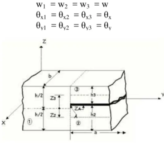
Figure 2 represents the cross-sectional view of a typical delamination crack tip where nodes of three plate elements meet together to form a common node. The undelaminated region is modeled by plate element 1 of thickness h, and the delaminated region is modeled by plate elements 2 and 3 whose interface contains the delamination (h2 and h3 are the thicknesses of the elements 2 and 3 respectively). The elements 1, 2 and 3 are freely allowed to deform prior to imposition of the constraints conditions. The nodal displacements of elements 2 and 3 at the crack tip are expressed as [5]
uj = u´j - (z – z′ j) xj (8) vj = v´j - (z – z′j) yj (9) wj = w´j (where, j = 2, 3) (10)
where z′j is the z-coordinate of mid-plane of element j and the above equation also holds good for element 1 and z′1 equal to zero. The transverse displacements and rotations at a common node have values expressed as [5]
w1 = w2 = w3 = w (11) x1 = x2 = x3 = x (12) y1 = y2 = y3 = y (13)
Figure 2 Plate elements at a delamination crack tip In-plane displacements of all three elements at crack tip are equal and they are related as
u′2 = u′1 - z′2 x (14) v′2 = v′1 - z′2 y (15) u′3 = u′1 - z′3 x (16) v′3 = v′1 - z′3 y (17)
where u′1 is the mid-plane displacement of element 1. Equations of (11) to (17) relating the nodal displacements and rotations of elements 1, 2 and 3 at the delamination crack tip, are the multipoint constraint equations used in finite element formulation to satisfy the compatibility of displacements and rotations. Mid-plane strains between elements 2 and 3 are related as,
{ ′}j = { ′}1 + z′j {K} (18)
where {K} is the curvature vector being identical at the crack tip for elements 2 and 3. This equation can be considered as a special case for element 1 and z′1 is equal to zero. In-plane stress-resultants, {N} and moment resultants, {M} of elements 2 and 3 can be expressed as,
{N}j = [A]j { ′}1 + (z′j [A]j + [B]j) {K} (19) {M}j = [B]j { ′}1 + (z′j [B]j + [D]j) {K} (where j = 2, 3) (20)
The elasticity matrix for the t-th sublaminate is then modified and is expressed in the form [12] (21) (22) (23) (24) (25)
where h is the thickness of the p-th sub-laminate. Thus the formulation based on the multi-point constraints condition leads to unsymmetric stiffness matrix. The resultant forces and moments at the delamination front for the elements 1, 2 and 3 satisfy the following equilibrium conditions,
{N} = {N}1 = {N}2 + {N}3 (26)
{M} = {M}1 + {M}2 + z′2 {N}2 + z′3 {N}3 (27)
{Q} = {Q}1 = {Q}2 + {Q}3 (28)
where {Q} denotes the transverse shear resultants. An eight noded isoparametric quadratic plate bending element of five degrees of freedom at each node (three translation and two rotations) is employed where shape functions are as follows [3]
Ni = (1 + i) (1 + i) ( i + i - 1) (for i=1,2,3,4) (29) Ni = (1 - 2) (1 + i) (for i = 5, 6) (30) Ni = (1 - 2) (1 + i) (for i = 6, 8) (31)
The principle displacements are expressed in terms of their nodal values by using the element shape functions and are given by,
8 1 u N ui i
i = =
8 1 v N vi i
i = =
8 1 w N wi i
i
=
= (32)
8 1Ni xi x i
θ = θ
=
8 1Ni yi y i
θ = θ
=
(33)
0
[ ] 0
0 0
o
A z A B
ij t ij ij o
Dt B z A D
ij t ij ij S ij t + = +
/ 2 [ ] [ ] / 2 o h ZtA Q dz
o
ij t h
Zt + =
− +
/ 2 / 2
[ ] [ ] ( ) [ ] [ ]
/ 2 / 2
o o
h Zt o h Zt o
B Q z z dz Q z dz z A
ij t h Zo t h Zo t ij t
t t
+ +
= − = −
− + − +
/ 2 2
[ ] [ ] ( )
/ 2
/ 2 2 / 2 2
[ ] 2 [ ] ( ) [ ] , 1, 2, 6
/ 2 / 2
o
h Zt o
D Q z z dz
ij t h o t
Zt
o o
h Zt o h Zt o
Q z dz z Q z dz z A i j
o t o t ij t
h Zt h Zt
+ = − − + + + = − + = − + − +
/ 2 2
[ ] [ ] ( )
/ 2 o
h Zt o
S Q z z dz
ij t o t
h Zt
+
= −
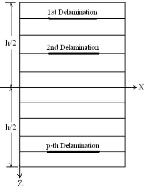
Figure 3 Laminate Geometry with multiple delaminations Multiple Delamination Modeling
A typical laminate with Nnumber of delaminations is considered as shown in figure 3. The nodal displacements within the sublaminate pare expressed as [12]
up = u′p + (z – z′p) x (34) vp= v′p + (z– z′p) y (35)
where u′p, v′p are the mid-plane displacements of the p-th sub-laminate and z′p (p= 1 to N+ 1) is the distance between the mid-plane of the original laminate and the mid-plane of the p-th sub-laminate. Applying constraint conditions that at any delamination boundary, the transverse displacements and rotations must have the same values at a common node, we get
u′p = u′ + zp x (36)
v′p = v′ + zp y (37)
Combining of (34), (35), (36) and (37) results in
{ }p = { }i + z′p {K} (38)
From (38), the stress and the stress resultant matrices for the p-th sub-laminate are calculated. The stress resultant matrices for the p-th sub-laminate are finally expressed as
(39)
(40)
(41)
( )
( )
Aij ZpAij Bij o
N
M p k
B Zp Bij Dij
ij p
ε +
=
+
44 45
54 55
Q A A
x xz
Q A A
y p p yz
γ γ
=
' / 2
'
[ ] 1, 2, 6
' / 2 h z p
A Qij dz where i
ij p p
h z p
+
= =
− +
(42)
(43)
where his the thickness of the p-th sub-laminate
3.0 Results and Discussion
Non-dimensional natural frequencies [ = n L2 √(ρh/D)] for conical shells (Rx = ∞) having a square plan-form (L/bo=1), curvature ratio (bo/Ry) of 0.5 and thickness ratio of (s/h) of 1000 are obtained corresponding to different speeds of rotation Ω = 0.0, 0.5 and 1.0 and relative distance, d/L=0.33, 0.5 and 0.66, considering three different angles of twist, namely =15°, 30° and 45°, in addition to the untwisted one ( =0°). Parametric studies are carried out with respect to twist angles, location of delamination and rotational speeds on natural frequencies of angle-ply composite shallow conical shells. The finite element formulation employs eight noded plate bending element with five degrees of freedom at each node. Material properties of graphite-epoxy composite [14] considered as E1=138.0 GPa, E2=8.96 GPa, =0.3, G12=7.1 GPa, G13=7.1 GPa, G23=2.84 GPa. Convergence studies are performed using uniform mesh division of (6x6) and (8x8) and the results are found to be nearly equal, with the difference being well within 1%.
3.1 Validation
Computer codes are developed based on present finite element method. The numerical results obtained are compared and validated with the results of published literatures [17, 13, 10, 8] as furnished in Table 1, Table 2, Table 3 and Figure 4, respectively. The numerical results show an excellent agreement with the previously published results and hence it demonstrates the capability of the computer codes developed and proves the accuracy of the analyses. The lower mesh size (6 x 6) consisting of 36 elements and 133 nodes, has been used for the analysis due to computational efficiency. The total number of degrees of freedom involved in the computation is 665 as each node of the isoparametric plate bending element is having five degrees of freedom comprising of three translations and two rotations.
Table 1. NDFF of graphite-epoxy isotropic rotating cantilever plate, considering L/bo=1, h/L=0.12, D=Eh3/{12(1- 2)}, =0.3 Ω Present FEM Sreenivasamurthy et al. [17]
0.0 3.4174 3.4368
0.2 3.4933 3.5185
0.4 3.7110 3.7528
0.6 4.0458 4.1287
0.8 4.4690 4.5678
1.0 4.9549 5.0916
Table 2 NDFF of three layered [ , - , ] graphite- epoxy twisted plates, L/bo=1, b/h=20, =30° Fibre Orientation Angle, Present FEM Qatu and Leissa [13]
15° 0.8618 0.8759
30° 0.6790 0.6923
45° 0.4732 0.4831
60° 0.3234 0.3283
' / 2
' '
[ ] ( )
' / 2 h Z p
B Qij z z dz
ij p p p
h Z p
+
= −
− +
' / 2
' 2 '
[ ] ( )
' / 2 h Z p
D Qij z z dz
ij p p p
h Z p
+
= −
− +
Table 3 Convergence Study for NDFF for pretwisted shallow conical shell with =0.3, a/s=0.7, s/h=1000, v=15° and o=30°
Ψ a/s Present FEM (6x6) Present FEM (8x8) Liew et al. [10]
0° 0.6 0.3524 0.3552 0.3599
0.7 0.2991 0.3013 0.3060
0.8 0.2715 0.2741 0.2783
30° 0.6 0.2805 0.2834 0.2882
0.7 0.2507 0.2528 0.2575
0.8 0.2364 0.2389 0.2417
Figure 4Influence of the relative position of delamination on the first natural frequency of the composite cantilever beam [8]
3.2 Effect of Stacking Sequence and Twist Angle
The arrangement of stacking sequence along with multiple delaminations is depicted in figure 5. From Table 4, it is observed that at stationary condition, non-dimensional fundamental natural frequencies (NDFF) of cross-ply conical shells attained maximum value for twist angle =0° and gradually decreased to a minimum value for twist angle =45° for all cases (i.e., at nd=2, 3 and 4). In other words, at stationary condition, non-dimensional fundamental frequencies decrease with the increase of twist angle for at nd=2, 3 and 4. On the other hand, at stationary condition, non-dimensional second natural frequencies (NDSF) of cross-ply conical shells also found to reduce with increase of twist angle for nd=3, 4 while the maximum value obtained at =15° and then reduces to minimum at =45° for nd=2. It is also observed that as the number of delamination increases, the stiffness of the shell decreases. At rotating condition, a typical trend observed for both NDFF and NDSF. The centrifugal stiffening effect (i.e., increase of structural stiffness with increase of rotational speed) is predominantly found at
=15° irrespective of number of delamination corresponding to NDFF.
Table 4 NDFF of cross-ply conical shells with mid-plane delamination, n=8, h=0.0004, s/h=1000, d/L=0.5, a/s=0.7, o=45°, v =20°.
nd=2 nd=3 nd=4
Ω=0.0 Ω=0.5 Ω=1.0 Ω=0.0 Ω=0.5 Ω=1.0 Ω=0.0 Ω=0.5 Ω=1.0
0° 0.2903 0.1128 0.3737 0.2593 0.2125 0.4113 0.2475 0.2411 0.4141
15° 0.1899 0.3742 0.4581 0.1749 0.3301 0.4528 0.1692 0.2750 0.4643
30° 0.1201 0.2868 0.2111 0.1117 0.2452 0.2873 0.1086 0.2356 0.1086
45° 0.0814 0.1657 0.1056 0.0767 0.1331 0.3293 0.0747 0.1182 0.3068
Table 5 NDSF of cross-ply conical shells with mid-plane delamination, n=8, h=0.0004, s/h=1000, d/L=0.5, a/s=0.7, o=45°, v =20°.
nd=2 nd=3 nd=4
Ω=0.0 Ω=0.5 Ω=1.0 Ω=0.0 Ω=0.5 Ω=1.0 Ω=0.0 Ω=0.5 Ω=1.0
0° 0.4256 0.4229 0.4070 0.4255 0.4233 0.4426 0.4254 0.4235 0.4262
15° 0.4297 0.6308 0.5939 0.4000 0.5758 0.5746 0.3857 0.4191 0.5736
30° 0.3128 0.5379 0.5202 0.2878 0.4982 0.5684 0.2756 0.4850 0.2756
45° 0.2168 0.4048 0.3831 0.1941 0.3655 0.5766 0.1827 0.3473 0.5510
3.3 Effect of Relative Frequency
Ω NDFF NDSF 0.5 0.00 0.60 1.20 1.80 2.40
0 15 30 45
T wist Angle
R el at ive F re que nc y 0.50 0.80 1.10 1.40 1.70 2.00
0 15 30 45
T wist Angle
R e la ti ve F re que nc y 1.0 0.60 1.40 2.20 3.00 3.80 4.60
0 15 30 45
Twist Angle Re la ti ve F re que nc y 0.60 1.40 2.20 3.00 3.80 4.60
0 15 30 45
Twist Angle Re la ti ve F re que nc y
Figure 6 Variation of relative frequencies with respect to NDFF and NDSF at Ω=0.5 and 1.0) of multiple delaminated eight layered graphite-epoxy cross-ply composite conical shells for various twist angles, considering h=0.0004, s/h=1000, a/s=0.7, o=45°, v =20°. 3.4 Effect of Twist along Span
A delamination of relative length a/L=0.33 is considered and this is centred at a relative distances of d/L=0.33 and 0.66 from the fixed end as indicated in Table 6 and Table 7. The delamination is considered at the interface of each layer. At stationary condition, NDFF are observed to decrease with the increase of twist angle for nd=4. At stationary condition, non-dimensional fundamental natural frequencies for both twisted and untwisted conical shells are found to increase as the delamination moves towards the free end. It is observed that with d/L=0.33at rotating condition (Ω=0.5 and 1.0), non-dimensional fundamental natural frequency found maximum at =15° and then decreases with increase of twist angle. In the contrast, for d/L=0.67, a typical trend is identified for Ω=0.5 and 1.0. It is also observed that the effect of centrifugal stiffening is only found with reference to NDFF in case of =0° and 15° corresponding to d/L=0.33 while the same with reference to NDSF obtained at =15° and 30° corresponding to d/L=0.67. On the other hand, at stationary condition, NDSF are found to decrease with the increase of twist angle for nd=4 at d/L=0.67 while for d/L=0.33, the maximum value of NDSF is obtained at = 15° and then decreases to minimum at =45°.
Table 6 NDFF of cross-ply conical shells with delamination along span, nd=4, n=8, h=0.0004, s/h=1000, a/s=0.7, o=45°, v=20°.
Ψ NDFF at d/L=0.33 NDFF at d/L=0.67
Ω=0.0 Ω=0.5 Ω=1.0 Ω=0.0 Ω=0.5 Ω=1.0
0° 0.2538 0.2705 0.4110 0.2654 0.4230 0.2074
15° 0.1630 0.3314 0.4847 0.1872 0.0425 0.3500
30° 0.0978 0.2900 0.2381 0.1199 0.0594 0.3710
Table 7 NDSF of cross-ply conical shells with delamination along span, nd=4, n=8, h=0.0004, s/h=1000, a/s=0.7, o=45°, v=20°.
Ψ NDSF at d/L=0.33 NDSF at d/L=0.67
Ω=0.0 Ω=0.5 Ω=1.0 Ω=0.0 Ω=0.5 Ω=1.0
0° 0.4241 0.4219 0.4363 0.4254 0.5379 0.4105
15° 0.4515 0.5228 0.5742 0.3275 0.3656 0.4816
30° 0.3246 0.5078 0.4909 0.2400 0.4018 0.6345
45° 0.2172 0.3909 0.3464 0.1665 0.5258 0.5017
3.5 Effect of Twist across Thickness
A parametric study is conducted for eight layered graphite-epoxy cross-ply composite conical shells under double delaminations according to stacking sequences as mentioned below (Figure 7):
Case 1: [0°//90°/0°/90°/90°/0°/90°//0°]
Case 2: [0°/90°//0°/90°/90°/0°//90°/0°]
Case 3: [0°/90°/0°//90°/90°//0°/90°/0°]
where ‘//’ indicates the locations of mid-plane delaminations.
Figure 7 Arrangement of double delamination in eight layered graphite-epoxy cross-ply composite laminate
In general, structural stiffness found to be reduced with the increase of twist angle. From Table 8, it is observed that NDFF decreases as the location of double delaminations moves towards the mid-plane invariant to twist angle. In other words, maximum NDFF is obtained for case 1, followed by case 2, followed by case 3. The similar trend is also identified for NDSF of the same. Hence, it leads to the fact that structural instability is more predominant towards the mid-plane of the cross-ply composite laminated structures.
Table 8 NDFF of cross-ply conical shells with delamination across thickness, nd=2, n=8, h=0.0004, s/h=1000, a/s=0.7, o=45°, v=20°.
NDFF NDSF
case 1 case 2 case 3 case 1 case 2 case 3
0.0 0.3102 0.2760 0.2680 0.4257 0.4256 0.4255
15.0 0.1986 0.1891 0.1789 0.4438 0.4210 0.4104
30.0 0.1244 0.1174 0.1138 0.3217 0.3018 0.2971
4.0 Mode Shapes
The mode shapes of NDFF and NDSF are shown in figure 8 for various twist angles ( =0°, 15°, 30°, 45°) at stationary condition considering eight layered graphite-epoxy symmetric delaminated cross-ply composite conical shells under quadruple delaminations. The fundamental frequency corresponds to the first torsion for both twisted and untwisted cases. The first span wise bending is observed at stationary condition corresponding to untwisted second natural frequencies.
Ψ Mode 1 Mode 2
0°
15°
30°
45°
Figure 8 Effect of twist on mode shapes (3D view) of NDFF and NDSF for graphite-epoxy cross-ply composite conical shells considering n=8, nd=4, Ω=0.0, h=0.0004, s/h=1000, a/s=0.7, o=45°, v =20°.
5.0 Conclusions
The following conclusions are drawn from the present study:
1. The finite element formulation presented in this paper can be successfully applied to analyze the natural frequencies of multiple delaminated conical shells for any particular laminate configuration.
2. In general, at stationary condition as the twist angle increases, non-dimensional fundamental frequency is found to reduce for multiple delaminated cross-ply composite conical shells.
3. At stationary condition, non-dimensional fundamental natural frequencies of pretwisted conical shells are found to increase as the delamination moves away from the clamped end.
5. The mode shapes of fundamental natural frequencies correspond to first torsion for both twisted and untwisted cases. The first span wise bending is observed only at stationary condition corresponding to untwisted second natural frequencies.
6. The non-dimensional frequencies obtained are the first known results which can be served as reference solutions for the future investigators.
Nomenclature
Rx Radius of curvature in x-direction Ry Radius of curvature in y-direction Rxy Radius of twist
Ψ Twist angle
Ω Non-dimensional speed of rotation (Ω′/ o)
Ω′ Actual angular speed of rotation
o Fundamental natural frequency of a non-rotating shell
ρ Mass density
L Length
bo Reference width Poisson’s ratio
h Thickness
d Distance of centerline of delamination from clamped (fixed) end v Vertex angle
o Base subtended angle of cone E1, E2 Elastic moduli along 1 and 2 axes
G12, G13, G23 Shear moduli along 1-2, 1-3 and 2-3 planes [M] Global mass matrix
[K] Elastic stiffness matrix [Kσ] Geometric stiffness matrix { } Global displacement vector λ Non-dimensional frequency uj, vj, wj Nodal displacements
u´j, v´j, w´j Mid-plane displacements x, y Rotation about x and y axes {Q} Transverse shear resultants [A] Extension coefficient
[B] Bending-extension coupling coefficient [D] Bending stiffness coefficients
{K} Curvature vector
{N} In-plane stress-resultants {M} Moment resultants { } Strains vector
, Local natural coordinates of the element x, y, z Local coordinate axes (plate coordinate system) n Number of layers
nd Number of delaminations a/s Aspect ratio
Natural frequency of rotating shell
NDFF Non-dimensional fundamental natural frequency NDSF Non-dimensional second natural frequency
References
[1] Andrews M. G., Massabò R., Cavicchi A., Cox B. N. (2009) Dynamic interaction effects of multiple delaminations in plates subject to cylindrical bending, International Journal of Solids and Structures, Vol.46, Issue 9, pp.1815-1833.
[2] Aymerich F., Dore F., Priolo P. (2009) Simulation of multiple delaminations in impacted cross- ply laminates using a finite element model based on cohesive interface elements, Journal of Composites Science and Technology, Vol.69, Issues 11-12, pp.1699-1709. [3] Bathe K. J. (1990) Finite Element Procedures in Engineering Analysis, PHI, New Delhi.
[4] Crawley, E. F. (1979) The Natural Modes of Graphite/Epoxy Cantilever Plates and Shells, Journal of Composite Materials, Vol. 13, pp. 195-205.
[5] Gim C. K. (1994) Plate Finite Element Modelling of Laminated Plates, Journal of Composite Structure, Vol.52, pp.157-168.
[7] Kee, Y. and Kim, J. (2004) Vibration Characteristics of Initially Twisted Rotating Shell type Composite Blades, Composite Structures, Vol. 64, No. 2, pp. 151-159.
[8] Krawczuk M., Ostachowicz W. and Zak A. (1997) Dynamics of Cracked Composite Material Structures, Journal of Computational Mechanics, Vol.20, pp.79-83.
[9] Leissa A. W., Lee J. K. and Wang A. J. (1984) Vibrations of Twisted Rotating Blades, Journal of Vibration, Acoustics, Stress, and Reliability in Design, Trans., ASME, Vol.106, pp.251-257.
[10] Liew K. M., Lim C. M. and Ong L. S. (1994) Vibration of pretwisted cantilever shallow conical shells, International Journal of Solids Structures, Vol.31, pp.2463-74.
[11] McGee O. G. and Chu H. R. (1994) Three-Dimensional Vibration Analysis of Rotating Laminated Composite Blades, Journal of Engineering for Gas Turbines and Power, ASME, Vol.116, pp.663–671.
[12] Parhi P. K., Bhattacharyya S. K. and Sinha P. K. (2001) Failure analysis of multiple delaminated due to bending and impact, Bull. Mater. Sci., Vol.24, pp.143–149.
[13] Qatu M. S. and Leissa A. W. (1991) Vibration studies for Laminated Composite Twisted Cantilever Plates, International Journal of Mechanical Sciences, Vol.33, pp.927-940.
[14] Qatu M. S. and Leissa A. W. (1991) Natural Frequencies for Cantilevered Doubly-Curved Laminated Composite Shallow Shells, Composite Structures, Vol.17, pp.227-255.
[15] Shaw, D., Shen, K. Y. and Wang, J. T. S. (1988) Flexural Vibration of Rotating Rectangular Plates of Variable Thickness, Journal of Sound and Vibration, Vol. 126, No. 3, pp. 373-385.
[16] Shen M. H. H. and Grady J. E. (1992) Free Vibrations of Delaminated Beams, Journal of AIAA, Vol.30, pp.1361–1370.
[17] Sreenivasamurthy S. and Ramamurthi V. (1981) Coriolis Effect on the Vibration of Flat Rotating Low Aspect Ratio Cantilever Plates, Journal of Strain Analysis, Vol.16, pp. 97-106.
[18]Wang, J. T. S., Shaw, D. and Mahrenholtz, O. (1987) Vibration of Rotating Rectangular Plates, Journal of Sound and Vibration, Vol. 112, No. 3, pp. 455-468.
Biographical notes
Mr. Sudip Dey is a research scholar in Mechanical Engineering Department, Jadavpur University, Kolkata, India. He completed Bachelor Degree in Mechanical Engineering from Jadavpur University, Kolkata, India. His field of specialization is Applied Mechanics. He has practical experience of approximately 5 years.

![Table 2 NDFF of three layered [ , - , ] graphite- epoxy twisted plates, L/b o =1, b/h=20, =30°](https://thumb-eu.123doks.com/thumbv2/123dok_br/16367623.190784/6.892.174.719.734.891/table-ndff-layered-graphite-epoxy-twisted-plates-l.webp)