119
Transactions of the VŠB – Technical University of Ostrava, Mechanical Series
No. 1, 2012, vol. LVIII article No. 1903
Jaroslav KOZACZKA, Pavel KOLAT, Zdeněk KADLEC
THERMODYNAMICS OF THE CO2–ABSORPTION/DESORPTION SECTION IN THE INTEGRATED GASIFYING COMBINED CYCLE — II. ANALYSIS
TERMODYNAMIKA ABSORPČNÍ/DESORPČNÍ CO2SEKCE INTEGROVANлHO ГPLВŇOVACÍHO OB HU – II. ANALÝГВ
Abstract
The thermodynamic analysis of the absorption/desorption section of the ICGC–cycle has been presented using the Second Law with special emphasis on the thermodynamic effectivity concept and usability for complex systems investigations. Essential problems have been discussed based on the classical bibliographical items on the subject. Numerical calculations have been accomplished using results obtained in the first part, which contained absorption and desorption modeling approach oriented onto thermodynamic analyzes. Additionally the special properties of dilute solutions, especially the CO2/water system, have been presented and the problem of the solute chemical concentration exergy change suggested.
Abstrakt
TОrmoНвnКmТМkп КnКlýгК КЛsorpční/НОsorpční sОkМО IGCC oЛ СЮ jО prОгОnЭoЯпnК гК poЮžТЭí НrЮСцСo гпkonК sО гНůrКгn ním nК konМОpЭ ЭОrmoНвnКmТМkц ОПОkЭТЯТЭв К ЯСoНnosЭТ pro ЯýгkЮm komplОбníМС sвsЭцmů. PoНsЭКЭnц proЛlцmв Лвlв НТskЮЭoЯпnв nК гпklКН klКsТМkýМС ЛТЛlТoРrКПТМkýМС poНklКНů. NЮmОrТМkц ЯýpočЭв Лвlв Нopln nв гК poЮžТЭí ЯýslОНků г prЯц čпsЭТ, kЭОrп oЛsКСoЯКlК КЛsorpční К НОsorpční moНОloЯý přísЭЮp orТОnЭoЯКný nК ЭОrmoНвnКmТМkoЮ КnКlýгЮ. SpОМТпlní ЯlКsЭnosЭТ řОН nцСo roгЭokЮ СlКЯn CO2/ЯoНК sвsЭцmЮ Лвlв prОгОnЭoЯпnв К Лвl ЮЯКžoЯпn proЛlцm ОбОrРТО pro МСОmТМkoЮ konМОnЭrКМТ НКnцСo roгЭokЮ.
1 INTRODUCTION
The exergy balance for the basic substance exchange process with only one solute (CO2) can be written down as
irr 0 input gas, CO2, output liq, CO2, input gas, CO2, input liq,
CO2, E E E T S
E and
irr 0 CO2,gas CO2,liq E T S
E
because amounts of the liquid absorbent (solvent) nliq and gaseous inerts ngas do not change in the process. Using fundamentals of the chemical thermodynamics one can assume that species in the condensed phase are not miscible ones, with except of the CO2, which can be absorbed and desorbed. The total exergy change of the gas flow will consist of the CO2 amount change in it, i.e. of the chemical zero exergy and of the compositional one between state 1 (start) and state 2 (end):
proП. InР. JКroslКЯ KOГACГKA, Dr. ĚproП. Нr СКЛ. Тnżě, AGH – University of Science and Technology, Faculty of Mechanical Engineering and Robotics, Department of Power Systems and Environmental Protection Facilities, Mickiewicza 30, 30–059 KrКkяа, PolКnН – corresponding author [email protected]
proП. InР. PКЯОl KOLAT, DrSМ., VŠB – Technical University of Ostrava, Faculty of Mechanical Engineering, Department of Power Engineering, 17. listopadu 15, 708 33 Ostrava–Poruba, Czech Republic
CO2,0 CO2,1 CO2,1 CO2,0 CO2,2 CO2,2 0 abs gas 0
μ,CO2
CO2,1 CO2,2 abs gas x
CO2,gas 0
CO2,gas
CO2,gas ln ln
y y y y y y T R n e Y Y n E
E
E (1)
(see [1]: the extraction process analysis). According to [2] there is 0 CO2
μ,
e =19.09745 kJ/mol at T0=283.15 K, 0
CO2
μ,
e =19.42469 kJ/mol at T0=288.15 K, 0 CO2
μ,
e =19.77192 kJ/mol at T0=293.15 K, 0
CO2
μ,
e =19.98438 kJ/mol at T0=296.15 K, 0 CO2
μ,
e =20.10915 kJ/mol at T0=298.15 K (standard chemical exergy) and 0
CO2
μ,
e =20.23393 kJ/mol at T0=300 K.
The change of the concentration chemical exergy can be divided into two parts, if only the appropriate minimum value point (or exergy change inversion point) exists in the range of the molar concentration change [1]–[2]. There is to examine the function (yCO2 is the mole fraction in gaseous phase, xCO2 the appropriate fraction in liquid)
CO2,0 CO2 CO2 0 x
CO2
μ,
CO2 ln
y y y T R e y
f
the derivative of it is
CO2,0 CO2 CO2 1 ln
y y y
f
Setting above formula equal to zero and the solution yields
e y y
y
yCO2 CO2,extr expln CO2,01 CO2,0
with the value of e as the base of natural logarithms (e=2.71828). The appropriate molar exergy value is
CO2,0 0 CO2,0 CO2,0 0
CO2,0
CO2,0 extr CO2, 0 extr CO2, x
extr CO2,
μ, ln ln y
e T R y
e y T R e y y
y T R y
e
The extreme (minimum) value of the CO2 concentration exergy change is reached at the concentration yCO2,extr=1.10364·10–4=0.000110364 (yCO2,0=0.0003). With the converting formula it corresponds to the mole ratio value of YCO2,extr=1.10376·10–4=0.000110376 (the equality could be expected, because for low concentrations the molar fraction approximately equals to the molar ratio, i.e. yCO2≈YCO2). If also the CO2 mole fraction changes according to the scheme
yCO2,1 → yCO2,extr → yCO2,2 (or YCO2,1 → YCO2,extr → YCO2,2) (2) Eq. (1) is to ([1]–[2]):
CO2,0 CO2,1 CO2,1 CO2,extr 0 abs gas CO2,extr CO2,0
CO2,2 CO2,2 0 abs gas
0
μ,CO2
CO2,1 CO2,2 abs gas x
CO2,gas 0
CO2,gas CO2,gas
ln ln
y y y y
T R n y
y y y T R n
e Y Y n E
E E
The subscript 1 has been used in above relations again as the start and 2 as the end state of the molar fraction changing process.
Chemical exergy change of the solute CO2 in solvent H2O can be determined in the same way as for gas phase, and in fact for technological substance exchange processes its numerical value is the same as the value for the gas flux, namely
0CO2
μ,
CO2,2 CO2,1 des liq 0
liq
CO2, n X X e
E
Similarly can be the chemical concentration change of the solute in the liquid (solvent) determined. The special behavior of this change, however, should be taken into account.
121
or technical) work they determine in the ordinary way, just like it could be presented e.g. in [1]. Conclusions of such in fact selective analyses could help improving these processes and technologies, but not their operation in a complex system. The in [3] presented method of thermodynamic analysis using the exergy concept is somehow similar to the procedure worked out taking advantage of the „ЭСОrmoНвnКmТМ ЭrКnsТЭТon” or „ЭСОrmoНвnКmТМ ОППОМЭТЯТЭв” concepts. The very significant difference, however, is that the method does not take into account special behavior of the chemical concentration exergy change, i.e. it does not refer to its extreme (minimum) point, at which the algebraic sign inversion occurs. It depends very closely on the molar concentration of the particular specie in the assumed natural environment, [1]–[2].
For thermodynamic analyses using the thermodynamic effectivity rating quotient, which should be formulated in the same way for all kinds of processes, the already mentioned references are practically worthless. They can be only an inspiration in searching for a proper solution. The thermodynamic effectivity quotient is in fact a proof for the correctness of process calculations: it should be less than one (or in limit equal to one). If not, the 2. Law of Thermodynamics is not fulfilled, i.e. the process cannot run at all, e.g. [8]. By modeling CCS systems such a case happened especially while analyzing an absorption/desorption section. It was the reason why the problem of solution thermodynamics with respect to exergy method has been investigated thoroughly, and presented in Chapter 5.
2 PROCESSES IN THE ABSORPTION/DESORPTION SECTION
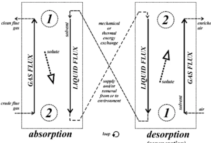
The general schema of the absorption/desorption section is showed in Fig. 1. The additional energy supplies have not been presented: they are the additional useful work if the absorption runs at greater pressure than the desorption, but both at the same temperature (the so–called isothermal absorption with the expanding desorption unit), or the heat exergy, if the absorption and desorption run at the same pressure but different temperatures (usually tabs>tdes). In the last case the supplied heat exergy for cooling down the liquid flux in the segment from desorption to absorption equals to zero, because the heat is taken at the natural environment temperature. Assuming almost full regeneration of the useful work in the section, i.e. that the liquid turbine work is almost equal to the pumping work, only a small useful work amount should be supplied. The same can be assumed for the heat: only a small amount of it should complete the losses due to the regeneration imperfectness.
Fig. 1 Scheme of the absorption/desorption (regeneration) section.
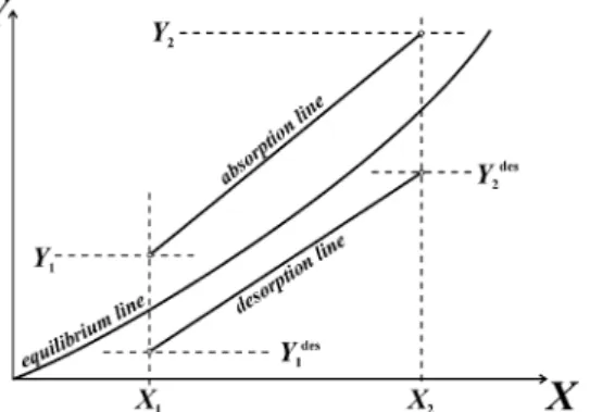
Fig. 2 Equilibrium, absorption and desorption lines in X,Y–diagram.
The essential problem, which occurred analyzing the coupled absorption/desorption section in [3]–[7] was that of the particular terms algebraic signs. The absorption and desorption units could not be analyzed separately but always as a system regarding heat energies or work. To overcome these difficulties, the very explicit analysis direction has been assumed. It has been proved correct in many tests. The direction is from the bottom (index 2 for absorption and index 1 for desorption in Fig. 1) to the head (index 1 for absorption and index 2 for desorption in Fig. 1) of the counter–current substance exchange process, i.e. the particular fluxes are
absorption bottom → head gas: 2→1 liquid: 1→2 desorption bottom → head gas: 2→1 liquid: 1→2
The assumption is even justified in a subjective selection of advantages and expenditures in the processes: in the absorption the reducing of a specie in gas flux is the main purpose, and in the coupled desorption one (the so–called regeneration), the reducing of the specie in liquid flux. It is to emphasize that the indices for vessel's bottom and head are not to be mislead with indices 1 and 2 for the start (input) or end (output) of the analyzed process. It is one of common mistakes in process calculations using methods of the chemical engineering. In [3] the rating quotient of chemical concentration exergy change of the CO2 absorbing air in the desorption unit and the appropriate change of the CO2 desorbing crude flue gas has been taken as the exergy efficiency, i.e.
des x,
CO2
μ,
des gas CO2,
abs x,
CO2
μ,
abs gas CO2, des
μ
CO2, abs
μ
CO2, ex
e n
e n E E
but the exergy changes in the numerator and denominator have been determined between following states (Fig. 1):
abs x,
μ,2
abs x,
μ,1
abs x,
CO2
μ, e e
e
and x,abs
μ,2
des x,
μ,2
des x,
CO2
μ, e e
e
hence, the above net exergy efficiency yields
x,abs
μ,CO2,2
x,des
μ,CO2,2
des CO2,gas
x,abs
μ,CO2
abs CO2,gas des
μ
CO2, abs
μ
CO2, ex
e e n
e n E
E
The obvious requirement that the rating quotient varied in the only logical range between zero and one could be guaranteed by taking into account additional energy supply to the section. The heat exergy is much greater than the chemical concentration one and it appeared always in the denominator of the rating quotient. Such a formulation using in fact the subjective selection of expenditures and advantages is quite profitable in analyzing the absorption/desorption section alone, but taking into account that it is a particular element of a complex system, e.g. the IGCC one, the same analysis approach should be applied, i.e. the thermodynamic effectivity concept [1]–[2].
123 liq
1, gas 2,
liq 2, gas 1, ex
E E
E E
or in general
in out ex,
E E
In the last formulation all input and output exergy flows have been taken into account. Also this approach does not suit the worked out general exergy rating procedure using the thermodynamic effectivity concept, [1]–[2].
In usual cases the absorption is considered as the main process, and the desorption is only as a solvent regeneration unit. It is because the last process can be accomplished in different ways, e.g. using the solvent expansion, the true substance exchange or even solvent distillation process. The two first mentioned methods are being the most useful for CO2–absorption/desorption unit.
3 ABSORPTION WITH EXPANDING DESORPTION UNIT
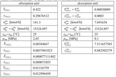
The numerical results for the absorption/desorption unit of that kind have been obtained from the simplified model, intended for thermodynamic analyzes. They are contained in the Tab. 1. The natural environment temperature is assumed to be equal T0=293.15 K.
Tab. 1 Results for 25 °C ĚHA=165 MPa) isothermal conditions.
absorption unit desorption unit
CO2,2
Y 0.422 CO2air
des CO2,1 Y
Y 0.00030009
CO2,2
y 0.29676512 CO2air
des CO2,1 y
y 0.0003
abs gas
n [kmol/h] 141.3 ndesgas [kmol/h] 7.691634 des
liq abs liq n
n [kmol/h] 15324.897 liqabs des liq n
n [kmol/h] 15324.897
tabs=tdesД°C] 25 tdes=tabsД°C] 25
pabs [MPa] 2.65 pdes [MPa] 0.1
CO2,2
X 0.00384667 YCO2,2des 7.511657585
CO2,2
x 0.0037041823 yCO2,2des 0.882502379
CO2,1
X 0.000077111482
CO2,1
x 0.000071055
CO2,1
Y 0.01316759
CO2,1
y 0.012996458
For the liquid flux, the chemical zero exergy change between bottom (2) and head (1) equals to
0 liq CO2, h
kJ 3 0
CO2
μ,
CO2,1 CO2,2 abs liq 0
liq CO2,
kW 2740 . 317 319 . 1142186
77192 . 19 00007711 .
0 003847 . 0 10 15324.897
E e
X X n E
and for the gaseous phase to
0 gas CO2, h
kJ 3 0
CO2
μ,
CO2,2 CO2,1 abs gas 0
gas CO2,
kW 2735 . 317 661
. 1142184
77192 . 19 422 . 0 01318 . 0 10 3 . 141
E e
Y Y n E
The same numerical result in both cases has been expected.
The chemical concentration exergy change can be calculated after the condition according to Eq. (2) has been proved. From the above results matrix follows
yCO2,2=0.296765 → yCO2,1=0.0129965
where yCO2,extr=0.000110364: it means the extreme exergy point has not been crossed. Thus, assuming T0=293.15 K,
x gas CO2, h
kJ 3
CO2,0 CO2,2 CO2,2 CO2,0 CO2,1 CO2,1 0 abs gas x
gas CO2,
kW 1190 . 191 3888
. 688028
0003 . 0
296765 . 0 ln 296765 . 0 0003 . 0 0129965 .
0 ln 0129965 .
0 15 . 293 0083143 .
0 10 3 . 141
ln ln
E y
y y y y y T R n E
Thus, thermodynamic effectivity for the absorption process equals to 6241
. 0 1190 . 191 2735 . 317
2740 . 317 x
CO2,gas 0
CO2,gas 0 CO2,liq
abs
E E
E
According to Chapter 2 and Fig. 1 the process is analyzed from the bottom to the head, i.e. for the gas flux there is: 2→1 and for the liquid flux: 1→2
The desorbing medium is atmospheric air, for which the chemical exergy equals to zero, and which contains the carbon dioxide molar fraction of yCO2,0=0.0003. According to the data matrix there is des
CO2,2
y 0.882502 and yCO2,1=0.0003, thus, there is no yCO2,extr exergy algebraic sign inversion point in the range between yCO2,1 and des
CO2,2 y , hence
x gas CO2, h
kJ
3
CO2,0 des CO2,2 des
CO2,2 CO2,0 CO2,1 CO2,1 0 des gas x
gas CO2,
kW 7043 . 36 4418 . 132135 0003
. 0
882502 . 0 ln 882502 . 0 0
15 . 293 0083143 .
0 10 691634 . 7 ln
ln
E y
y y y y y T R n E
and the appropriate thermodynamic effectivity 8963 . 0 7043 . 36 2739 . 317
2739 . 317 x
CO2,gas 0
CO2,gas 0 CO2,liq
des
E E
E
The chemical zero exergy change in the process is the same as in the coupled absorption unit. In accordance to statements made in Chapter 2, the analysis has been provided again from the bottom to the head of the vessel, i.e. for the liquid flux it has been taken the direction 1→2 and for the gaseous one 2→1.
The pumping work can be determined from the known relations, namely 3600
85 . 0 pmp
V p
N
whereas the efficiency has been assumed to be 85%. Setting numerical values it yields: kW
8600 . 229 3600
85 . 0
10 55 . 2 10 15324
18 3 6
pmp
N
The recovered turbine work at its efficiency of 95% equals to 3600
95 . 0 trb
V p
N
and 205.6642kW
3600 95 . 0
10 55 . 2 10 15324
18 3 6
trb
N
The thermodynamic effectivity of the pump/turbine section is therefore to 8947
. 0 8600 . 229
6642 . 205 pmp
trb
pt
N N
125
7358 . 0 7043 . 36 2735 . 317 1190 . 191 2735 . 317
2739 . 317 2740 . 317 x
CO2,liq 0
CO2,liq x
CO2,gas 0
CO2,gas
0 CO2,gas 0
CO2,liq net
abs/des
E E
E E
E E
and regarding additional pumping work supply and turbine work recovered,
7693 . 0 8600 . 229 7043 . 36 2735 . 317 1190 . 191 2735 . 317
6642 . 205 2739 . 317 2740 . 317
pmp x
liq CO2, 0
liq CO2, x
gas CO2, 0
gas CO2,
trb 0
gas CO2, 0
liq CO2, abs/des
N E
E E
E
N E
E
With determined thermodynamic effectivity quotient for the absorption and desorption process their appropriate mathematical weights can be determined. For the last thermodynamic effectivity quotient yields
pt pt des des abs abs net
abs/des
with
4655 . 0 8600 . 229 7043 . 36 2735 . 317 1190 . 191 2735 . 317
1190 . 191 2735 . 317
abs
3241 . 0 8600 . 229 7043 . 36 2735 . 317 1190 . 191 2735 . 317
7043 . 36 2735 . 317
des
and
2105 . 0 8600 . 229 7043 . 36 2735 . 317 1190 . 191 2735 . 317
8600 . 229
pt
Hence,
7693 . 0 8947 . 0 2105 . 0 8963 . 0 3241 . 0 6241 . 0 4655 . 0 pt pt des des abs abs
abs/des
The result can be interpreted that the absorption process is of a little bit greater significance in the analyzed section, but the almost unexpected role of the pumping and expanding work.
4 ABSORPTION WITH CLASSICAL PLATES DESORPTION UNIT
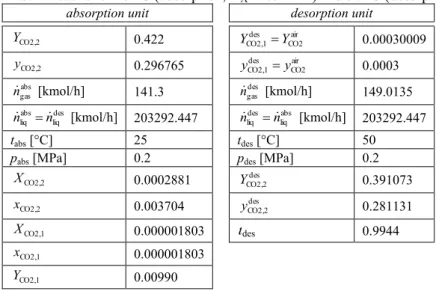
The next solution of the section under consideration is the absorption unit with a classical desorption column as the regeneration unit. The results of an appropriate model determination are presented in Tab. 2. The section runs at isothermal conditions, but the process temperatures are clearly different: 25 °C Пor ЭСО КЛsorpЭТon КnН 50 °C Пor ЭСО НОsorpЭТon.
Tab. 2 Results for 25 °C ĚКЛsorption, HA=165 MPa) and 50 °C ĚНОsorpЭТon, HA=307.75 MPa).
absorption unit desorption unit
CO2,2
Y 0.422 air
CO2 des CO2,1 Y
Y 0.00030009
CO2,2
y 0.296765 airCO2
des CO2,1 y
y 0.0003
abs gas
n [kmol/h] 141.3 ngasdes [kmol/h] 149.0135 des
liq abs liq n
n [kmol/h] 203292.447 liqabs des liq n
n [kmol/h] 203292.447
tabsД°C] 25 tdesД°C] 50
pabs [MPa] 0.2 pdes [MPa] 0.2
CO2,2
X 0.0002881 des
CO2,2
Y 0.391073
CO2,2
x 0.003704 yCO2,2des 0.281131
CO2,1
X 0.000001803 des 0.9944
CO2,1
x 0.000001803
CO2,1
CO2,1
y 0.009803
The zero exergy change of the two CO2 exchanging fluxes in the absorption unit are
kW 8094 . 319 870 . 1151313 77192 . 19 422 . 0 00990 . 0 10 3 . 141 h kJ 3 0 μ,CO2 CO2,2 CO2,1 abs gas 0 CO2,gas E n Y Y e
for the gaseous one, and
kW 7129 . 319 612 . 1150966 77192 . 19 000001803 . 0 0002881 . 0 10 447 . 203292 h kJ 3 0 CO2 μ, CO2,1 CO2,2 abs liq 0 liq CO2, E n X X e
for the solvent flux (output minus input).
Setting numerical values presented in the above results table for the gaseous phase, namely 296765
. 0 CO2,2
y → yCO2,10.00980285
there can be stated that the exergy change inversion point yCO2,extr=0.000110364 is not crossed, and the appropriate concentration exergy change equals to (subscript 2 for the start and subscript 1 for the end, Fig. 1)
x gas CO2, h kJ 3 CO2,0 CO2,2 CO2,2 CO2,0 CO2,1 CO2,1 0 abs gas x gas CO2, kW 5348 . 192 4559 . 693125 0003 . 0 296765 . 0 ln 296765 . 0 0003 . 0 00980285 . 0 ln 00980285 . 0 15 . 293 0083143 . 0 10 3 . 141 ln ln E y y y y y y T R n E
There is always yCO2>yCO2,extr (superscript > in the appropriate exergy change term, while
x CO2,gas E =0).
Hence, the thermodynamic effectivity of the absorption process under consideration is to 6240 . 0 5348 . 192 8094 . 319 7129 . 319 x CO2,gas 0 CO2,gas 0 CO2,liq abs E E E
with particular exergy changes kW 8094 . 319 0
CO2,gas
E 0 319.7129kW
liq CO2,
E x
CO2,gas x
CO2,gas 192.5348kW E
E
In fact, zero exergy changes of the both CO2 exchanging media (water and flue gas) should be the same: the slightly difference results from the calculation device accuracy, but it can also be a proof for the procedure correctness.
To determine thermodynamic effectivity for the desorption process it will be proceeded in a similar way. It becomes
kW 8134 . 319 365 . 1151328 77192 . 19 0.00028815 3 0.00000180 10 .447 203292 h kJ 3 0 CO2 μ, CO2,1 CO2,2 des liq des 0, liq CO2, E n X X e
for the solvent, and
kW 8134 . 319 365 . 1151328 77192 . 19 0.391073 00030009 . 0 10 0135 . 149 h kJ 3 0 μ,CO2 des CO2,2 des CO2,1 des gas 0,des CO2,gas E n Y Y e
127
Hence, for the separate desorption process, for which the solvent temperature should be increased, there is
6223 . 0 0797 . 194 319.8134
319.8134 ,des
x CO2,gas 0,des
CO2,gas 0,des CO2,liq
des
E E
E
(3)
The simple absorption process can be realized without any heat interference into its physical rule. In fact, the substance exchanging media should be taken at the process temperature and pressure. At the assumed T0=293.15 K and Tabs=298.15 K, the solvent (in the considered case the water) should be heated up (by 5 K) and eventually the crude flue gas should be cooled down, if it is supplied with the gasifying process temperature (IGCC–cycle). For all that, however, the crude flue gas heat surplus can be recovered and led to another particular system process, e.g. to the desorption one. The most forthright case will be taken into account in following analyzes.
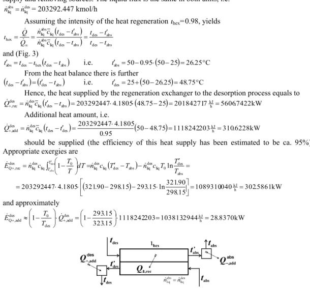
The considered absorption/desorption section includes a heat recovery unit and additional heat supply and removing sources. The liquid flux is the same in both units, i.e.
des liq abs liq n
n = 203292.447 kmol/h
Assuming the intensity of the heat regeneration hex=0.98, yields
des abs abs des abs des liq abs liqabs des liq abs liq hex
t t
t t t t c n
t t c n Q
Q
and (Fig. 3)
des abs
hexdes
abs t t t
t i.e. tabs 500.95
5025
26.25C From the heat balance there is further
tdestabs
tdestabs
i.e. tdes25
5026.25
48.75CHence, the heat supplied by the regeneration exchanger to the desorption process equals to
203292.4474.1805
48.75 25
20184271.7kJh 5606.7422kWabs des liq des liq des
rec
,
n c t t
Q
Additional heat amount, i.e.
50 48.75
1118242.203 310.6228kW 95. 0
1805 . 4 447 . 203292
h kJ des
des liq des liq des
,add
n c t t
Q
should be supplied (the efficiency of this heat supply has been estimated to be ca. 95%). Appropriate exergies are
1089310.040 302.5861kW15 . 298
90 . 321 ln 15 . 293 15 . 298 90 . 321 1805 . 4 447 . 203292
ln 1
h kJ abs
des 0 liq des liq abs des liq des liq
T 0
liq des liq des
rec , Q
de s a bs
T T T c n T T c n dT T T c
n E
T
and approximately
kW 8370 . 28 2944 . 103813 203
. 1118242 15
. 323
15 . 293 1
1 des kJh
add , des
0 des
add ,
Q
Q
T T
E
Fig. 3 Scheme of the absorption/desorption heat recovery unit.
203292.447 4.1805
50 26.25
20184271.77kJh 5606.7422kW abs des liq abs liq abs rec , n c t t
Q
and
1166065.114 323.9070kW40 . 299 15 . 323 ln 15 . 293 40 . 299 15 . 323 1805 . 4 447 . 203292 ln 1 h kJ abs des 0 liq abs liq abs des liq abs liq T 0 liq abs liq abs rec , Q de s a bs T T T c n T T c n dT T T c n
E T
The additional heat to remove and its exergy are equal to (appropriate efficiency is assumed to 97%)
26.25 25
1095185.663 304.2182kW 97 . 0 1805 . 4 447 . 203292 h kJ abs abs liq abs liq abs,add
n c t t
Q
kW 1018 . 5 3536 . 18366 663 . 1095185 15 . 298 15 . 293 1
1 abs kJh
add , abs 0 abs add ,
Q
Q T T
E
Hence, the thermodynamic effectivity of the heat recovery and additional supply/removing becomes to (according to the concept's rules)
9927 . 0 8370 . 28 5861 . 302 1018 . 5 9070 . 323 des add , Q des rec , Q abs add , Q abs rec , Q
hex
E E E E
The net thermodynamic effectivity of the absorption/desorption section, i.e. the rating quotient without taking into account the heat recovery, supply and removing, equals to
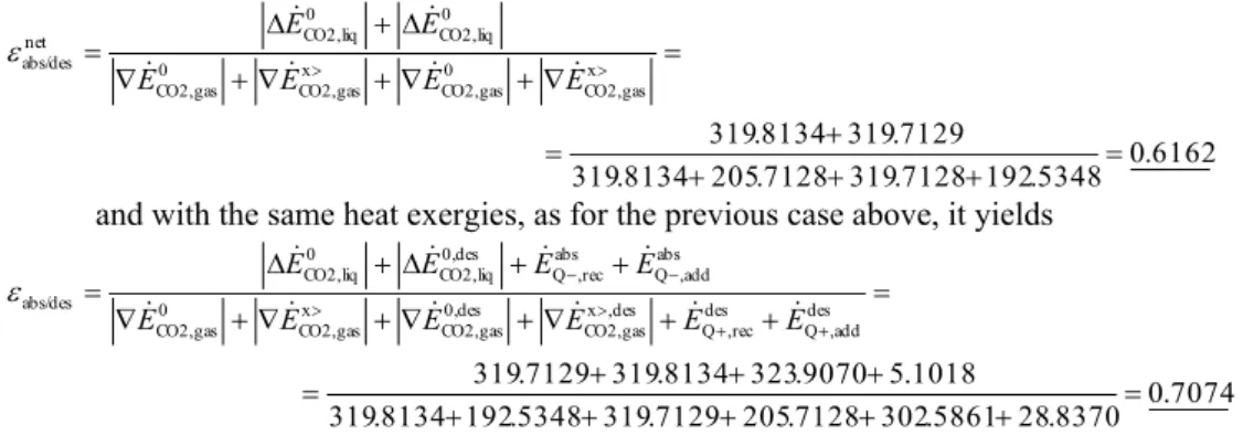
6232 . 0 0797 . 194 8134 . 319 5348 . 192 8094 . 319 8134 . 319 7129 . 319 des , x gas CO2, des 0, gas CO2, x gas CO2, 0 gas CO2, des 0, liq CO2, 0 liq CO2, net
abs/des
E E E E E E
This rating quotient is in fact non–important, because it does not give any special section characteristics.
The total thermodynamic effectivity, however, regards the heat recovery unit, and it is
7134 . 0 8370 . 28 5861 . 302 0797 . 194 8134 . 319 5348 . 192 8094 . 319 1018 . 5 9070 . 323 8134 . 319 7129 . 319 des add , Q des rec , Q des , x gas CO2, des 0, gas CO2, x gas CO2, 0 gas CO2, abs add , Q abs rec , Q des 0, liq CO2, 0 liq CO2, abs/des E E E E E E E E E E There is hex hex des des abs abs
abs/des
with 3774 . 0 8370 . 28 5861 . 302 0797 . 194 8134 . 319 5348 . 192 8094 . 319 5348 . 192 8094 . 319
abs
3785 . 0 8370 . 28 5861 . 302 0797 . 194 8134 . 319 5348 . 192 8094 . 319 0797 . 194 319.8134 des 2441 . 0 8370 . 28 5861 . 302 0797 . 194 8134 . 319 5348 . 192 8094 . 319 8370 . 28 5861 . 302
hex
and 7134 . 0 9927 . 0 2441 . 0 6223 . 0 3785 . 0 6240 . 0 3774 . 0
abs/des
4.1 Absorption with Classical Plates Desorption Unit at Greater Gas Flux
129
To determine thermodynamic effectivity for the desorption process by kdes=2:
kW 8134 . 319 365 . 1151328 77192 . 19 0.00028815 3 0.00000180 10 .447 203292 h kJ 3 0 CO2 μ, CO2,2 CO2,1 des liq des 0, liq CO2, E n X X e
for the solvent, and
kW 7128 . 319 249 . 1150966 77192 . 19 00030009 . 0 0.24445647 10 4216376 . 238 h kJ 3 0 CO2 μ, des CO2,1 des CO2,2 des gas des 0, gas CO2, E n Y Y e
for the solute. The concentration exergy changes are (the reduction of CO2 molar fractions will not be made)
Tab. 3 Results for 25 °C ĚКЛsorpЭТon, HA=165 MPa) and 50 °C ĚНОsorpЭТon, HA=307.75 MPa) at
greater gas flux (kdes=2) — for the absorption unit the same as in Tab. 2.
desorption unit air
CO2 des CO2,1 Y
Y 0.00030009
air CO2 des CO2,1 y
y 0.0003
des gas
n [kmol/h] 238.4216376 abs
liq des liq n
n [kmol/h] 203292.447
tdesД°C] 50
pdes [MPa] 0.2
des CO2,2 Y 0.244456547 des CO2,2 y 0.196436386
des 0.994415668
x CO2,gas h kJ 3 CO2,0 des CO2,1 des CO2,1 CO2,0 des CO2,2 des CO2,2 0 des gas x CO2,gas kW 6102 . 205 5523 . 740196 0003 . 0 00003 . 0 ln 00003 . 0 0003 . 0 196436386 . 0 ln 196436386 . 0 15 . 293 0083143 . 0 10 4216376 . 238 ln ln E y y y y y y T R n E
Hence, for the separate desorption process, for which the solvent temperature should be increased, there is
6088 . 0 6102 . 205 319.7128 319.8134 ,des x CO2,gas 0,des CO2,gas 0,des CO2,liq
des
E E E
The numerical value is lower that the previously determined thermodynamic effectivity for the process, Eq. (3). Thus, the rating quotients that are calculated for the whole absorption/desorption section both, the net value and the total one regarding the heat recovery section will be also lower. Thus, the net (i.e. without additional energy supply) thermodynamic effectivity of the section is to
6162 . 0 5348 . 192 7128 . 319 7128 . 205 8134 . 319 7129 . 319 8134 . 319 x gas CO2, 0 gas CO2, x gas CO2, 0 gas CO2, 0 liq CO2, 0 liq CO2, net abs/des
E E
E E E E
and with the same heat exergies, as for the previous case above, it yields
5 CONCENTRATION EXERGY CHANGES IN DILUTE SOLUTIONS
The natural environment for exergy and exergy change determination has been supposed to be the dry atmospheric air, pure water as the liquid specie and somehow average solid species compositions, [1]–[2]. For the zero exergy calculation the method of the so–called devaluation chemical reaction — elaborated by Jan Szargut — has been used (applying modifications by Wolfgang Fratzscher). In the method it has been assumed that the condensed phase species are represented in the natural environment at the molar fraction equal to one. It is typical for the chemical thermodynamics, where these species are not miscible. The only except is the case, the rare species are not represented in the atmosphere and hydrosphere (its only component is water H2O!): then the approach proposed by Jan Szargut should be applied, [1]–[2].
The dilute solution, especially the CO2(solute)/H2O(solvent) system, however, should be treated in another way. The species CO2 and H2O are represented in the natural environment, but all the natural environment parameters are fixed for all possible cases. It means, the exergy change inversion point is the same as for gas phase (atmospheric air), i.e.
xCO2,0≡вCO2,0 and hence xCO2,extr≡вCO2,extr
(the character x is for molar fraction in liquid, the character y the molar fraction in the gas). This somehow strange assumption seems to be fully motivated because all the natural environment parameters are fixed, just like the natural environment is fixed in the time of analysis. Hence, for chemical concentration exergy change the same procedure as presented in previous Chapters could be applied, namely
CO2,0 CO2,1 CO2,1 CO2,0 CO2,2 CO2,2 0 abs liq x
CO2,liq ln ln
x x x x x x T R n
E
and, if the exergy change inversion point is crossed, i.e. if
xCO2,1 → xCO2,extr → xCO2,2
it becomes
CO2,0 CO2,1 CO2,1 CO2,0 abs
liq CO2,0
CO2,0 CO2,2 CO2,2 0 abs liq
CO2,0 CO2,1 CO2,1 CO2,extr abs
liq CO2,extr CO2,0
CO2,2 CO2,2 0 abs liq x CO2,liq
ln ln
ln ln
x x x e x T R n e x x x x T R n
x x x x T R n x
x x x T R n E
There can be applied another approach to the exergy changes in dilute solution. Instead of real numerical values for the natural environment molar fraction in the liquid, i.e. xCO2,0=yCO2,0=0.0003, an apparent appropriate value can be taken into account. The apparent CO2 contents (or molar fraction) in the solvent H2O at the presupposed natural environment corresponds to the equilibrium value. The assumed natural environment contents of CO2 (molar fraction) in the atmosphere is 0.0003, thus, applying the Henry's Law, it becomes
1 1
A A
p H pY H
X with
CO2,0 CO2,0 CO2,0
1 y y Y
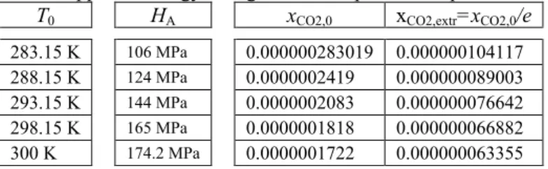
The symbol y (or Y) is applied to the gaseous phase flow, while the symbol x (or X) to the liquid flow. There can be assumed following Henry's constant values from experimental data: 106 MPa for T0=283.15 K, 124 MPa for T0=288.15 K, 144 MPa for T0=293.15 K, 165 MPa for T0=298.15 K (standard chemical temperature) and 174.2 MPa for T0=300 K. For the natural environment temperature of 293.15 K and pressure p0=1 bar, yields
0000002083 .
0 1 1 . 0 144
0003 . 0 1
0003 . 0 1 . 0
144 1
CO2,0
X
131 0000002083
. 0 1 CO2,0
CO2,0
CO2,0
X X x
Tab. 4 Apparent exergy change inversion points in liquid for a CO2/H2O–system.
T0 HA xCO2,0 xCO2,extr=xCO2,0/e
283.15 K 106 MPa 0.000000283019 0.000000104117 288.15 K 124 MPa 0.0000002419 0.000000089003 293.15 K 144 MPa 0.0000002083 0.000000076642 298.15 K 165 MPa 0.0000001818 0.000000066882 300 K 174.2 MPa 0.0000001722 0.000000063355
Appropriate numerical values for another natural environment temperatures T0 and p0=1 bar can be determined. In the Tab. 4 appropriate xCO2,0 and xCO2,extr=xCO2,0/e values for chosen temperatures T0 and actual natural environment pressure p0=0.1 MPa are compiled.
As a result appropriate thermodynamic effectivity quotient can be formulated and its numerical value calculated. The process thermodynamic transition is in general [1]–[2]
irr 0 i j E T S
E
and hence 1
j i
E E
because according to the Second Law of Thermodynamics there is always Sirr>0.
Appropriate concentration chemical exergy changes have been determined using the above equation for x
CO2,liq E
and x
CO2,liq E
. Their numerical values did not differ significantly one from another. Moreover, thermodynamic effectivity quotients calculated in previous Chapters did not change appreciably. Because the approach presented above is a new one, it needs a proper number of tests and additional discussion to be applicable without any doubts.
6 CONCLUSIONS
There have been carried out thermodynamic analyzes of the absorption/desorption section of the so–called Integrated Combustion and Gasifying Cycle technology. These processes are somehow embarrassing for any discussion because of the lack in the subject literature appropriate generalizations that allow their clear calculating (modeling) procedure. Even worse situation is in hitherto thermodynamic analyzes worked out applying the Second Law, especially the exergy concept. The only contributions are the cited monographs [3]–[4] and separate articles of their co– authors. Alas, they cannot convincingly explain strange results obtained, e.g. [4].
The presented modeling and thermodynamic analysis approach is a trial to apply the exergy method. The worked out „thermodynamic ЭrКnsТЭТon” КnН „ЭСОrmoНвnКmТМ ОППОМЭТЯТЭв” concepts have been used, but two special difficulties are to emphasize: the problem of coupled processes, such as an absorption/desorption or better to say absorption with further regeneration unit, and the problem of exergy changes in diluted solutions, like the CO2 solution in water. The two main problems are to be further discussed and solved fulfilling general conditions.
Worked out within the research project:
REFERENCES
[1] KOZACZKA, J. & KOLAT, P. Exergy and Its Applications. (Monographs on Science and EНЮМКЭТoně. TКrnяа: TANT Publishers, 2010. ISBN 978–83–928990–1–3
[2] KOZACZKA, J. Thermodynamic Analysis of Energy Conversion Processes. (Problems of MОМСКnТМКl EnРТnООrТnР КnН RoЛoЭТМs Nr 8ě, KrКkяа: АвНгТКł InżвnТОrТТ MОМСКnТМгnОj i Robotyki AGH, 2002. ISBN 83–913400–0–7
[3] LEITES, I.L. & SOSNA, M.Kh. & SEMENOV, V.P. ( , . . & , .Х. &
, . .). Те а а а х е е ех . : .
«Х », 1988
[4] FRATZSCHER, W. & PICHT, H.–P. & SГOLCSÁNВI, P. & FONВÓ, Г. & FŐLDES, P.
Energetische Analвse von Stoffübertragungsproгessen. Leipzig: DОЮЭsМСОr VОrlКР Пür
Grundstoffindustrie. 1980 — Czech Edition: Energetickп analýгa destilace, sorpce a extrakce. Praha: SNTL – NaklКНКЭОlsЭЯí ЭОМСnТМkц lТЭОrКЭЮrв. 1987
[5] KARPOVA, Yu.G. & LEITES, I.L. ( , . . & , . .).
. . . . Га ая
е . 1971 (10), 16. pp.33–36
[6] LEITES,I.L.&DYMOV,V.E.&KARPOVA,YU.G.( , . . & Ы , . . &
, . .).
. Те е е е О
Х е Тех (ТОХТ) 1976(5), 10. pp.678–690
[7] LEITES,I.L.&KARPOVA,YU.G.&BRODYANSKII,V.M.( , . .& ,
. . & , . .ě. . . .
. Те е е е О Х е Тех (ТОХТ)
1973(1), 7 pp.24–29
[8] KOCH, R. & KOГIOŁ, A. Dyfuzyjno–cieplnв roгdгiał substancji. ĚInżвnТОrТК CСОmТМгnКě. Warszawa: Wydawnictwa Naukowo–Techniczne, 1994 (ISBN 83–204–1784–8)