Vol-7, Special Issue-Number4-June, 2016, pp713-722 http://www.bipublication.com
Research Article
Charge and bilateral discharge of battery in hybrid vehicles with ability of
reactive power compensation with technology V2G
Sajad Davtalab and Daryoush Nazarpour 1
Department of Electrical EngineeringUrmia Branch, Islamic Azad University, Urmia, Iran
1
[email protected], [email protected]
ABSTRACT:
Posing V2G theory for hybrid vehicles can create opportunities on the operation of the grid, and can even put it in row of renewable energy sources. One of the needs in the operation of power systems on which is special attention is voltage control and reactive power of grid. Hybrid cars with V2G capability can be utilized for this work and is the subject of this article.An appropriate control method for reactive power control of grid by using V2G is suggested in this article. Reactive powers, dc-link voltage and reactive power in the suggested control method are independent and can be controlled separately. Section of battery and transducer of hybrid vehicle with V2G capability have been simulated and the suggested controller has been applied to it in order to evaluate the suggested control method. The results achieved from the simulation show that reactive power injected into the grid or received from it can be controlled independent of its reactive power with appropriate transient state.
Keywords: hybrid vehicle, V2G, reactive power control, voltage control, simulation
1. INTRODUCTION
Objectives such as reducing atmosphere pollution and reducing greenhouse gases emission, remove any hazardous chemical materials, energy productivity, reducing solid and liquid waste materials, education and public awareness and informing, preservation and rehabilitation of natural resources, reducing harmful environmental effects are considered for sustainable development with the help of environment management trend. In the last three decades on the one hand the concern on finishing fossil resources and on the other hand environmental complex issues has posed the use of non-fossil and cleaner fuel sources.In this regard, using electric vehicles instead of combustion vehicles, applying solar energy, fuel cell and super capacitors have been suggested as alternative methods. Electricity generation by using renewable energies can be considered as the front line of the fight against environmental destruction. On the other hand, the transportation industry in its not too distant future image is looking for substitution of conventional vehicles with electric vehicles.
Electric vehicles have been currently entered the market of road transportation. The infrastructure necessary to implement the vehicle to the grid will be also provided in the near future. Perhaps, the thing that its absence can be more seen in the meantime is the lack of a coherent executive program to actualize the concept of vehicle to the grid.
It is expected in the coming years, sale of power electric vehicles (PEV) to be increased as an economical alternative for conventional vehicles with internal combustion engine (ICE). PEV vehicles provide more operational returns and as a result increase fuel cost saving [1]. But large numbers of connections of PEV to electricity grid has created concerns about grid reliability, particularly in the low voltage distribution grids, because maximum grid load will be greatly increased with this trend [2]
On-Board chargers convert ac voltage of the grid to dc voltage and usually have the power transfer capability in one direction. On-Board charger can also support power quality and do some tasks such as reactive power compensation (capacitive or inductive), voltage regulation, filtering additional harmonics and power factor correction by using more advanced topology and controllers compared to conventional and common methods available in the market [3] [4] Provision of reactive power by using On-Board chargers connected to the distribution system has also inherent disadvantages such as mobility of PEV vehicles (Chargers) and limitations of these chargers and residential outputs. Providing ancillary services by using Off-Board chargers are more useful than On-Board chargers, because Off-Board charging stations are not mobile and have higher nominal power, and can be assigned to the electricity grid by annual contracts.
Off-Board charging stations that have been located in shopping centers, restaurants or other public places are immobile, and have higher nominal power compared to On-Board chargers and can provide ancillary services to the grid. With the increase of tendency to use PEV vehicles in the sub-grid services, more attempts must be done to show usages of charger systems and its operation results. Use of PEV vehicles to provide local reactive power has been studied and investigated in the related literature [6] [7] [8] [5].
In addition, smart charge by using V2G (Vehicle to Grid) vehicles makes grid operation more useful and more hopeful compared to smart charge without these vehicles [9]. But there are
not still enough tests in subject literature to validate V2G vehicles, which can show control operation of grid power provision mechanism and provide the ability to compare this option with other options [10].
In fact, Europe Union (EU) has pledged to develop significantly the existing infrastructures for electric vehicles with the aim of multiplying the number of Europe charging stations. This part is a new strategy to launch low-carbon vehicles industry in Europe [11] [12].
Smart charge operations by using vehicles to grid (V2G) are useful and interesting because of its advantages in cases related to long-term operations of electricity grids. In the future, the equipment and tools want to inform their customers about power charge of PEV vehicles, and thereby creates motivation in them [13]. With the increasing interest in using V2G vehicles in electricity grids, researches have been conducted to evaluate the operation of the battery-fed bilateral transducer both in independent state and in the state of connected to the grid.
2. Definition of V2G and its usages
The energy required to charge the battery can be supplied from the grid. This capability is called vehicle to grid (V2G). In addition, when the vehicle is connected to the grid, the battery can restore energy to the grid. This is called capability to supply the grid load by vehicle. More electric vehicles charging requires about 2 hours to 8 hours. This time does not need to begin from charger connection moment. Therefore, electric vehicle is a type of flexible load, which can be considered of examples of demand response.
Table 1: Annual net profit of vehicle owner from V2G for variety of vehicles and market in California in dollar [16]
Vehicle type Peak load Reserve Battalion Set the frequency
battery electric vehicle 267 720 3162
Fuel cell electric vehicle 50. (loss) to 1226 2430 to 2685 2984- (loss) to 811
Hybrid electric vehicle 322 1581 759- (loss) Table 1 shows propriety of electric vehicles for
different markets in California. Vehicles can be utilized in ancillary services market as areserve, so that vehicles parked and connected to the grid be able to act as reserve providers through discharging their battery when require immediate electric power injection by the vehicles to power grid because of occurrence of an event.In addition, electric vehicles can also participate in frequency regulation market and help to maintain grid frequency in its allowable range through charging and discharging electric power in accordance with operator commands
exhaust gas from conventional vehicles are among the reasons leading to the need to move toward the use of electric vehicles.
Proper management in shaping electric vehicles fleet in power system can create an appropriate opportunity from this phenomenon, which potentially can be posed as a challenge for power industry to help electricity market. the results of a study has been mentioned in reference [15] according to which in 2020 with 25% penetration of electric vehicles in 13 areas of United States of America, about 160 new power plants will be needed if each vehicle began to charge at five o'clock in the afternoon.But confronting with this great challenge in the debate of power system planning by charge and discharge management of vehicles can be done at much less costs. Electric vehicles and V2G debate can reduce contamination resulting from emergency and peak power production resources. The existence of a large fleet of electric vehicles that can provide electrical energy storage service leads to fix the problem of output power fluctuations of renewable units.
Economic advantages and increase of reliability resulting from V2G for power system is a secondary advantage for it. V2G advantages include items such as peak reduction, and consequently filling decrease in transmission grid. Reducing line losses, postponing investment for transfer sector, and reducing operation time under the pressure of power system are among other advantages of this type of vehicles for the grid. Another operation of these vehicles is in ancillary services market. 3. Simulation of V2G charge and discharge with ability to control reactive power
Simulation of electric vehicles with batteries that are capable of restoring power to the grid has been done in this chapter of the article. The goal is to control reactive power injected or absorbed by it in both charge and discharge modes.
3.1 Modeled grid
Modeling implementation method to simulate V2G to control reactive power injected or received from the grid has been done in this part. The modeled grid is as Figure (1) that its information is as Tables (2) and (3):
Figure 1: Model used in V2G battery and the grid connected to i
Table 2: Characteristics of the ac part of grid
Quantity Value Quantity
Rated voltage 400 Rated voltage
Nominal frequency 50 Nominal frequency
Type of SC To Ground Grounded Star
Equivalent resistance 15.784 Ohm
Self-equivalent 0.62 Mili Henri
Filter capacitor 200 Micro Farad
Filter inductor 1.2 Mili Henri Table 3: Characteristics of the dc part of grid
Quantity Value Unit
Battery nominal voltage 220 Volt
Rate of capacity 15 Ampere hour
Maximum voltage 260 Volt
Maximum capacity 18 Ampere hour
Internal resistance 0/1333 Ohm
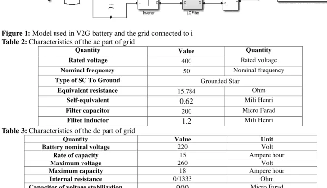
3.2 Suggested method of transducer control
A new method based on making reactive power control reference based on Park's Transformation has been suggested in this part of the article to control reactive power in the side of the grid. Dq0 or Park's Transformation or direct-perpendicular-zero transformation is a mathematical transformation, which is used to simplify the analysis of three-phase circuit. The use of Dq0 transformation reduces three quantities to two quantities of dc when three-phase circuit is balanced. Simplified calculations can be performed on delusive dc quantities and then ac three-phase results can be obtained by using reverse transformation. Equation 1 shows this transformation:
That isθ= ωtand ω=2πf
However Park's transformation to normal mode voltages of the system that is as the equation 2, Vd and Vq are obtained as equation 3.
Values of momentary active and reactive powers in reference Park's transformation frame are calculated as equations (4) and (5):
We will have equations (6) and (7) for active and reactive powers according to equation (3):
This result with regard to equations (6) and (7) can be deduced that in conditions that upper hand ac grid of the model is a strong grid and / or suitable filters have been used to compensate voltage, active power is dependent on Id flow-and reactive power is dependent on Iq flow. So reference active and reactive power can be made for transformation as equations (8) and (9).
Moreover, given that today transducers in which switches of MOSFET- or IGBT-type are more used and have very low and negligible losses, injected or received active power in both ac and dc parts of the transducer can be considered equal. Given that power consumption at the side of dc is calculated as equation Pdc=Vdc×Idc, and active power at the side of ac as equation (6), therefore equation (10) is set as follows:
(10)
So Id can be used to control dc bus voltage.
PI cont roller +
- -
-PI cont rol ler +
-1/ Vdc
PI cont roller
+-
-+
1/ Vdc
-KQ
KP
Cart To Pol ar
t o PW M
Iq
Id
Vd
Vd c
Qref
Pr ef
Vd c*
Figure 2: Suggested control loop
-Pmax Pmax
-Qmax Qmax
Active Power
R
ea
c
ti
v
e
P
o
w
e
r P < 0Q > 0 P > 0Q > 0
P > 0 Q < 0 P < 0
Q < 0
It can be seen according to Figure (2) showing the suggested control loop that the reactive power is controlled through Qref and active power through Pref that are calculated via equations (8) and (9). As noted, dc bus voltage is proportional to Id and it can be used to control dc bus voltage. This work has been done as can be seen in Figure (2). Given that reactive and active powers are somewhat interdependent, this relation has been made by using KP and KQ coefficients
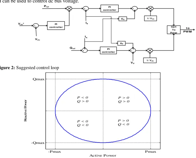
Active powers received and injected through transducer are as Figure 3 that each of the first to fourth areas shows corresponding status to modes listed below. Four work areas have been considered for transducer according to Figure (3) as follows:
1. First area: Transducer discharge and injecting reactive power into the grid (P> 0 and Q> 0) 2. Second area: Transducer charge and injecting reactive power into the grid (P <0 and Q> 0) 3. Third area: Transducer charge and receiving reactive power from the grid (P <0 and Q <0) 4. Fourth area: Transducer discharge and receiving reactive power from the grid (P> 0 and Q <0)
4. Results obtained from simulation
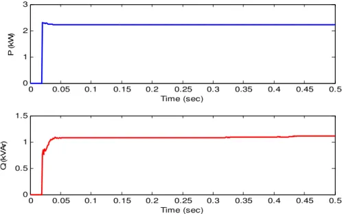
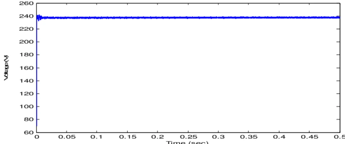
4.1 V2G operation as discharge and reactive power injection into the grid
0 0.05 0.1 0.15 0.2 0.25 0.3 0.35 0.4 0.45 0.5
-200 0 200 400
V
o
lt
a
g
e
(
V
)
Time (sec)
Va Vb Vc
0 0.05 0.1 0.15 0.2 0.25 0.3 0.35 0.4 0.45 0.5
-20 -10 0 10 20
C
u
rr
e
n
t
(A
)
Time (sec)
Ia Ib
Ic
Figure 4: Figure of voltage and current waves at the side of source in mode of V2G operation as discharge and reactive power injection into the grid
V2G mode has been modeled in mode of active and reactive powers injection into the grid in this section. As has been shown in Figure (4), the values of active and reactive powers are equal to +2.3 kW and +1.2 kVAr, respectively and dc bus voltage has also transient fast mode.
0 0.05 0.1 0.15 0.2 0.25 0.3 0.35 0.4 0.45 0.5
0 1 2 3
P
(
k
W
)
Time (sec)
0 0.05 0.1 0.15 0.2 0.25 0.3 0.35 0.4 0.45 0.5
0 0.5 1 1.5
Q
(
k
V
A
r)
Time (sec)
0 0.05 0.1 0.15 0.2 0.25 0.3 0.35 0.4 0.45 0.5 60
80 100 120 140 160 180 200 220 240 260
V
o
lt
a
g
e
(
V
)
Time (sec)
Figure 6: dc bus voltage in a mode of V2G operation as discharge and reactive power injection into the grid
4.2 V2G operation as charge and reactive power injection to grid
In the case of V2G operation in charge mode, active power is taken from the grid to charge the battery. So, transferred power from transducer to the grid should also be negative. This has been shown in Figure 8. As can be seen, the value of injected active power is equal to -4.9 kW and the value of reactive power injected into the grid is also equal to 1.9 kVAr.So transducer in this mode acts as capacitive from the perspective of reactive power and compensates reactive power of the grid. This mode can be utilized when there is a voltage drop in the grid and required amount of reactive power to be planned proportional to voltage drop existing in the grid.
0 0.05 0.1 0.15 0.2 0.25 0.3 0.35 0.4 0.45 0.5 -400
-200 0 200 400
V
o
lt
a
g
e
(
V
)
Time (sec)
Va Vb Vc
0 0.05 0.1 0.15 0.2 0.25 0.3 0.35 0.4 0.45 0.5 -40
-20 0 20 40
C
u
rr
e
n
t
(A
)
Time (sec)
Ia Ib Ic
Figure 7: Figure of voltage and current waves at the side of source in mode of V2G operation as discharge and reactive power injection into the grid
Figure 8: active and reactive power injected into the grid in mode of V2G operation as charge and reactive power injection into the grid
0 0.05 0.1 0.15 0.2 0.25 0.3 0.35 0.4 0.45 0.5
-6 -4 -2 0
P
(
k
W
)
Time (sec)
0 0.05 0.1 0.15 0.2 0.25 0.3 0.35 0.4 0.45 0.5
0 1 2 3
Q
(
k
V
A
r)
0 0.05 0.1 0.15 0.2 0.25 0.3 0.35 0.4 0.45 0.5 60
80 100 120 140 160 180 200 220 240
V
o
lt
a
g
e
(
V
)
Time (sec)
Figure 9: 2 dc bus voltages in mode of V2G operation as charge and reactive power injection into the grid
4.3 V2G operation as charge and receiving reactive power from the grid
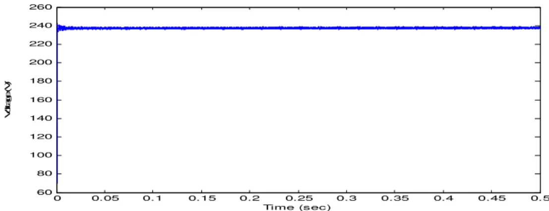
V2G in charging mode and receiving reactive power from the grid have been simulated in this section. As can be seen, the amount of voltage distortion has been increased. This is because of harmonic reactive powers that are taken from the grid in this mode. Values of active and reactive powers injected into the grid from the side of V2G are equal to is 4.9 kW and 1.1 kVAr, respectively. As can be seen in Figure (10), dc bus voltage has fast transient mode and has quickly reached constant mode.
0 0.05 0.1 0.15 0.2 0.25 0.3 0.35 0.4 0.45 0.5
-200 0 200 400
V
o
lt
a
g
e
(
V
)
Time (sec)
Va Vb Vc
0 0.05 0.1 0.15 0.2 0.25 0.3 0.35 0.4 0.45 0.5
-40 -20 0 20 40
C
u
rr
e
n
t
(A
)
Time (sec)
Ia Ib
Ic
Figure 10: Figure of voltage and current waves of source in mode of V2G operation as charge and receiving reactive power from the grid
0 0.05 0.1 0.15 0.2 0.25 0.3 0.35 0.4 0.45 0.5 -6
-4 -2 0
P
(
k
W
)
Time (sec)
0 0.05 0.1 0.15 0.2 0.25 0.3 0.35 0.4 0.45 0.5 -1.5
-1 -0.5 0
Q
(
k
V
A
r)
Time (sec)
0 0.05 0.1 0.15 0.2 0.25 0.3 0.35 0.4 0.45 0.5 60
80 100 120 140 160 180 200 220 240
V
o
lt
a
g
e
(
V
)
Time (sec)
Figure 12: 2 dc bus voltages in mode of V2G operation as charge and receiving reactive power from the grid
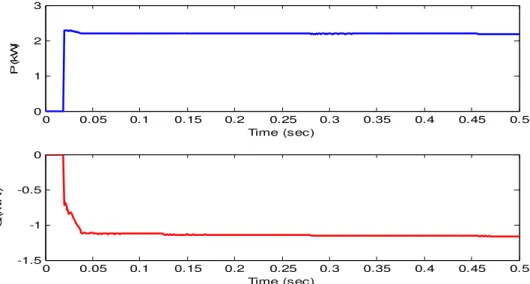
4.4 V2G operation as discharge and injection reactive power into the grid
0 0.05 0.1 0.15 0.2 0.25 0.3 0.35 0.4 0.45 0.5
-200 0 200 400
V
o
lt
a
g
e
(
V
)
Time (sec)
Va
V b
Vc
0 0.05 0.1 0.15 0.2 0.25 0.3 0.35 0.4 0.45 0.5
-20 -10 0 10 20
C
u
rr
e
n
t
(A
)
Time (sec)
I a Ib
Ic
Figure 13: Figure of voltage and current waves of source in mode of V2G operation as discharge and receiving reactive power from the grid
As can be seen in Figure (13), ac bus voltage has less distortion than mode of V2G operation as charge and receiving reactive power from the grid. The reason for this is distortions damped by active power flowed (resistance current) from the transducer to the grid. It can be seen by observing active and reactive power injected into the grid that values of active and reactive power injected into the grid are equal to 2.2 kW and 1.1 kVAr, respectively.
0 0.05 0.1 0.15 0.2 0.25 0.3 0.35 0.4 0.45 0.5 0
1 2 3
P
(
k
W
)
Time (sec)
0 0.05 0.1 0.15 0.2 0.25 0.3 0.35 0.4 0.45 0.5 -1.5
-1 -0.5 0
Q
(
k
V
A
r)
Time (sec)
0 0.05 0.1 0.15 0.2 0.25 0.3 0.35 0.4 0.45 0.5 60
80 100 120 140 160 180 200 220 240 260
V
o
lt
a
g
e
(
V
)
Time (sec)
Figure 15: 2 dc bus voltages in mode of V2G operation as discharge and receiving reactive power from the grid
5. CONCLUSION
As was simulated and analyzed, transducers used for vehicles that feed from electricity grid can be used as reactive power controller. Control of reactive power by these transducers is independent of the conditions of charging or discharging them. A suggested method based Park's transformation has been offered in this thesis to control reactive power injected into or received from the grid. The suggested method has this capability to control reactive and active powers of the grid independently and maintain dc bus voltage related to V2G battery constant.The results obtained from the simulation shows sure operation of the suggested method. Receiving control active power from ac grid and dc-link voltage control has been integrated with each other and has become as a single controller in this article. In conditions that ac grid upper hand of the model to be a strong model and / or suitable filters have been used to compensate voltage, active power is dependent on Id and reactive power is dependent on Iq current. V2G transducer can be used as shunt reactor or capacitor in the grid by controlling the injected or received reactive power of V2G transducer.
6. LIST OF REFERENCES
1. Kisacikoglu, M.C., et al., PHEV-EV charger technology assessment with an emphasis on V2G operation. 2012, Oak Ridge National Laboratory (ORNL(
2. Luo, Z., et al., Optimal coordination of plug-in electric vehicles plug-in power grids with cost-benefit analysis—Part I: Enabling techniques. Power Systems, IEEE Transactions on, 2013. 28(4): p. 3546-3555. 3. Kisacikoglu, M.C., B. Ozpineci, and L.M.
Tolbert, EV/PHEV bidirectional charger assessment for V2G reactive power
operation. Power Electronics, IEEE Transactions on, 2013. 28(12): p. 5717-5727. 4. Ferreira, R.J., et al. A new bi-directional
charger for vehicle-to-grid integration. in Innovative Smart Grid Technologies (ISGT Europe), 2011 2nd IEEE PES International Conference and Exhibition on. 2011. IEEE. 5. Bojrup, M., Advanced control of active
filters in a battery charger application. 1999: Department of Industrial Electrical Engineering and Automation, Lund Institute of Technology (Institutionen för industriell elektroteknik och automation, Lunds tekniska högs.
6. Mitra, P., G.K. Venayagamoorthy, and K. Corzine, SmartPark as a Virtual STATCOM. Smart Grid, IEEE Transactions on, 2011. 2(3)): p. 445-455
7. Kisacikoglu, M.C., B. Ozpineci, and L.M. Tolbert. Examination of a PHEV bidirectional charger system for V2G reactive power compensation. in Applied Power Electronics Conference and Exposition (APEC), 2010 Twenty-Fifth Annual IEEE. 2010. IEEE.
8. Falahi, M., et al., Potential power quality benefits of electric vehicles. Sustainable Energy, IEEE Transactions on, 2013. 4(4): p. 1016-1023.
9. Mets, K., et al. Exploiting V2G to optimize residential energy consumption with electrical vehicle discharging. in Smart Grid Modeling and Simulation (SGMS), 2011 IEEE First International Workshop on. 2011. IEEE.
10.D., et al., Transient stability analysis of SMES for smart grid with vehicle-to-grid operation. Applied Superconductivity, IEEE Transactions on, 2012. 22(3): p. 5701105-5701105.
target for reducing CO2 emissions from new passenger cars. 2012, Technical report, European Commission
12.Izadian, A., N. Girrens, and P. Khayyer, Renewable energy policies: A brief review of the latest US and EU policies. Industrial Electronics Magazine, IEEE, 2013. 7(3): p. 21-34.
13.Liu, H., et al., Decentralized vehicle-to-grid control for primary frequency regulation considering charging demands. Power Systems, IEEE Transactions on, 2013. 28(3): p. 3480-3489.
14.Choi, J., et al., High-efficiency grid-tied power converter for battery energy storage. IEEE transactions on power delivery, 2014. 29(3): p. 1514-1515.
15.Kesler, M. and E. Ozdemir, Synchronous-reference-frame-based control method for UPQC under unbalanced and distorted load conditions. Industrial Electronics, IEEE Transactions on, 2011. 58(9): p. 3967-3975. 16.W. Kempton, J. Tomic, S. Letendre, A.
Brooks, and T. Lipman,“Vehicle-to-Grid Power: Battery, Hybrid, and Fuel Cell Vehicles asResources for Distributed Storage,” Institute of Transportation Studies (UCD), 2001.