ABOUT THE STUDY OF REQUESTS BUCKLING VERIFICATION OF THE ELEMENTS
OF POWER PLANT PROPULSION
Anastase PRUIU1
Daniel MARASESCU2
Dorin-Silviu BANU3 Ion Adrian GIRBA4
1
Professor PhD Eng., Marine Engineering and Naval Weapons Department
2
PhD attendee Eng., Marine Engineering and Naval Weapons Department
3
PhD attendee Eng. Military Technical Academy
2
PhD attendee Eng. Military Technical Academy
Abstract: On study based of requests from the power propulsion plant, the authors develop in this paper a study of buckling heat engine piston rod at the head of the cross, the strut rod and shaft intermediaries for power propulsion plant.
Key words: buckling, strut rod, propulsion power plant
Introduction
For parts-metallic structures of naval propulsion plants, compression can be applied to situations of exploitation when axial forces grow, the issue of verification of buckling.
This consists of:
a. determining the critical buckling force b. determining the critical buckling pressure c. determination the coefficient of safety buckling d. depending on the results obtained can take precautions to avoid operational achieving critical force buckling
e. resizing piece to increase the safety coefficient buckling
Buckling phenomenon is dangerous because it is irreversible.
Critical buckling tension may fall to limit proportionalities (elasticity) of the material from which it is made corresponding to the piece, is called elastic buckling.
If the tension is above the critical elastic buckling, buckling is called the elastic-plastic.
Either: Fcrf [kN] - critical buckling force
Fef [kN] - effective buckling force
The safety coefficient of buckling is determined with:
[1]
with the condition like cf> 1
Depending on the functional importance of the piece of naval propulsion power plant, buckling safety coefficient will be accepted in a particular reference domain.
Critical buckling force
[KN] [2]
E [kN/m2] - elastic modulus specific for the material it is made subjected to compressive load the piece. For the manufacture of the materials used in naval propulsion power plant, determination of the elastic modulus should be performed in the material strength laboratories recognized by classification societies and for materials recognize by them.
Imin[m 4
] - moment of inertia calculated for minimal section of the piece put under compression. This is calculated based on the geometric size and shape of the respective section.
Lf 2
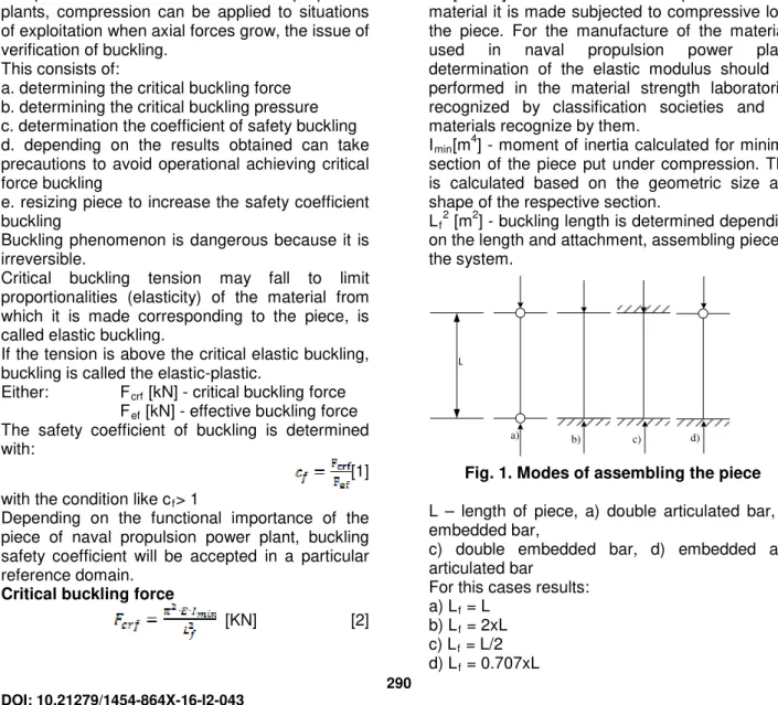
[m2] - buckling length is determined depending on the length and attachment, assembling piece in the system.
L
a) b) c) d)
Fig. 1. Modes of assembling the piece
L – length of piece, a) double articulated bar, b) embedded bar,
c) double embedded bar, d) embedded and articulated bar
For this cases results: a) Lf = L
b) Lf = 2xL
c) Lf = L/2
d) Lf = 0.707xL 290
DOI: 10.21279/1454-864X-16-I2-043
For fixing arrangement are taken into account two perpendicular planes of section fixing joints, otherwise for articulated plan Lf = L, but for the
normally plan be considered embedded, so Lf =
L/2 what will lead to the determination of two critical forces buckling.
Fcrf (PO) [kN] - critical buckling force for articulated
plan – called oscillation plan
Fcrf (PI) [kN] - critical buckling force for normal plan
on oscillation plan – called embedded plan
To equalize the two critical buckling forces, proceed to mass redistribution of minimum calculation section so:
I min(PO) = 4 x Imin (PI) [3]
By equalizing critical safety buckling forces is obtained equalization of critical safety buckling coefficients for both plans assembling piece
B.1.Checking the buckling of piston rod
D [m] 0.5 0.72 Sp[m
2
] 0.196 0.407 dTP[m] 0.15 0.216
S [m] 2 3
LTP [m] 3 4.5
E [kN/m2] 2.1x10⁸ 2.1x10⁸ Imin [m
4
] 2.48x10⁻⁵ 1.068x10⁻⁴ pmaxaid [bar] 135 140
pmaxaid [kN/m 2
] 135x102 140x102 pmaxdss [bar] 150 155
pmaxdss
[kN/m2]
150x102 155x102
Fpmax [kN] 29.4x10 2
63x102 Fcrf [kN] 2.28x10
4
4.373x10⁴ cf[-] 7.75 6.941
B.2. Checking the buckling of piston rod
D [m] 0.84 1.08 Sp[m
2
] 0.554 0.855 dTP[m] 0.25 0.32
S [m] 3.2 2.8 LTP [m] 5 5
E [kN/m2] 2.1x10⁸ 2.1x10⁸ Imin [m
4
] 1.91x10⁻⁴ 5.044x10⁻⁴ pmaxaid [bar] 140 140
pmaxaid [kN/m 2
] 140x102 140x102 pmaxdss [bar] 155 155
pmaxdss
[kN/m2]
155x102 155x102
Fpmax [kN] 85.87x10 2
132x102 Fcrf [kN] 6.33x10
4
16.73x10⁴ cf[-] 7.38 12.6
D [m] - cylinder diameter; Sp [m2] – piston area;
dTP [m] – rod of piston diameter; S [m] - piston
stroke; LTP [m] – rod of piston length; Imin[m 4
] – inertia moment; pmaxard [kN/m
2
] –maximum combustion pressure; pmaxdss [kN/m
2
] – maximum
pressure for safety valve; Fpmax[kN] – maximum
forte of pressure; σefmax [kN/m 2
] - maximum effective tension; Fcrf [kN] – critical force buckling;
σcrf [kN/m 2
] - critical tension buckling; cf [-] -
buckling safety factor; ; [4]
; [5]
; [6]
; [7]
[8]
; [9]
; [10]
1
2
3
4
5
Fig.2 piston rod and connecting rod for MAN S46 [B6]
1 – piston, 2 – piston rod,
3 - cross head, 4 – connecting rod, 5 - crankshaft
291 DOI: 10.21279/1454-864X-16-I2-043
C.1. Checking the buckling of connectingstrut rod
D [m] 0.5 0.72
S [m] 2 3
LTB [m] 2.63 3.95
Fpmaxdss [kN] 29.4x10 2
63x102 E [kN/m2] 2.1x10⁸ 2.1x10⁸ dTB[m] 0.18 0.22
Imin [m 4
] 5.15x10⁻⁵ 1.27x10⁻⁴ Fcrf PO [kN] 15.43x10
3
1.688x10⁴
cf PO [-] 5.25 2.679
Fcrf PI [kN] 6172x10 3
6.72x10⁴
cf PI [-] 21 10.716
C.2. Checking the buckling of connecting strut rod
D [m] 0.84 1.08 S [m] 3.2 2.8 LTB [m] 4.21 4
Fpmaxdss [kN] 85.87x10 2
132x102 E [kN/m2] 2.1x10⁸ 2.1x10⁸ dTB[m] 0.28 0.35
Imin [m 4
] 3.01x10⁻⁴ 7.37x10⁻⁴ Fcrf PO [kN] 3.52x10
4
9.55x10⁴
cf PO [-] 4.099 7.23
Fcrf PI [kN] 14.08x10 4
38.2x10⁴
cf PI [-] 16.39 28.92
LTB [m] – connecting rod length; λ = 0.25 ÷ 0.38;
; dTB – connecting rod diameter;
Fcrf (PO) [kN] - critical buckling force for connecting
rod oscillation plan;
Fcrf (PI) [kN] - critical buckling force for connecting
rod embedded plan;
σcrf(PO) [kN/m2] - critical tension buckling for
connecting rod oscillation plan; σcrf(PI) [kN/m
2
] - critical tension buckling for connecting rod embedded plan;
cf(PO) [-] - buckling safety factor for connecting rod
oscillation plan;
cf(PI) [-] - buckling safety factor for connecting rod
embedded plan;
; [11]
; [12]
; [13]
; [14]
; [15]
; [16]
; [17]
; [18]
Material limitations [B4]
Where shafts may experience vibratory stresses close to the permissible stresses for transient operation, the materials are to have a specified minimum ultimate tensile strength (σB) of 500
N/mm2. Otherwise materials having a specified minimum ultimate tensile strength () of 400 N/mm2 may be used.
For use in the following formulae in this UR, σB is
limited as follows:
- For carbon and carbon manganese steels, a minimum specified tensile strength not exceeding 600 N/mm2 for use in M68.5 and not exceeding 760 N/mm2 in M68.4.
- For alloy steels, a minimum specified tensile strength not exceeding 800 N/mm2.
- For propeller shafts in general a minimum specified tensile strength not exceeding 600 N/mm2 (for carbon, carbon manganese and alloy steels).
Where materials with greater specified or actual tensile strengths than the limitations given above are used, reduced shaft dimensions or higher permissible vibration stresses are not acceptable when derived from the formulae in this UR.
Shaft diameters [B4]
Shaft diameters are not to be less than that determined from the following formula:
[19]
where:
d = minimum required diameter in [mm] di = actual diameter in [mm] of shaft bore
d0 = outside diameter in [mm] of shaft. If the bore
of the shaft is ≤0.40xd0, the expression
may be taken as 1.0
F = factor for type of propulsion installation
F1= 95 for intermediate shafts in turbine
installation, diesel installations with hydraulic (slip type) couplings, electric propulsion installations F2= 100 for all other diesel installations and all
propeller shafts
k = factor for the particular shaft design features, see M68.6
n0 = speed in revolutions per minute of shaft at
rated power
p = rated power in kW transmitted through the shaft (losses in gearboxes and bearings are to be disregarded)
σB = specified minimum tensile strength in N/mm2
of the shaft material, see M68.3
292 DOI: 10.21279/1454-864X-16-I2-043
The diameter of the propeller shaft located forward of the inboard stern tube seal may be gradually reduced to the corresponding diameter required for the intermediate shaft using the minimum specified tensile strength of the propeller shaft in the formula and recognizing any limitations given in M68.3. [4]
Fig. 3 The arrangement of ship shafting system [B5]
E.1.Checking of buckling intermediary shaft
DE 4T DE 2T Pe [kW] 10000 20000
n [rpm] 450 90 n0 [rpm] 90 90
F 100 100
σB[N/mm 2
] 650 650
K 1 1
d [mm] 425 535 d [m] 0.425 0.535
L [m] 8.5 10.7 Mm [kNm] 1061 2122
Wn1 [Nd] 20 20
Wn1 [m/s] 10.29 10.29
FA1 [kN] 972 1944
Fcrf [kN] 1.84x10 5
2.91x10⁵ cf1 [-] 189 150
Wn2 [m/s] 2 2
FA2 [kN] 5000 9487
cf2 [-] 37 31
Wn3 [m/s] 0.5144 0.5144
FA3 [kN] 1.944x10 4
3.69x10⁴ cf3 [-] 9.46 7.88
E.2. Checking of buckling intermediary shaft
GT ST
Pe [kW] 30000 60000
n [rpm] 5000 3000 n0 [rpm] 100 100
F 95 95
σB[N/mm 2
] 650 650
K 1 1
d [mm] 592 746 d [m] 0.592 0.746 L [m] 11.84 14.92 Mm [kNm] 2865 5730
Wn1 [Nd] 20 20
Wn1 [m/s] 10.29 10.29
FA1 [kN] 2916 5831
Fcrf [kN] 3.56x10 5
5.68x10⁵ cf1 [-] 122 96.55
Wn2 [m/s] 2 2
FA2 [kN] 15002 30000
cf2 [-] 23 19
Wn3 [m/s] 0.5144 0.5144
FA3 [kN] 5.832x10 4
1.166 x10⁵ cf3 [-] 6.10 4.867
Pe [kW] – effective power; n [rpm] –RPM of
thermal machinery; n0 [rpm] – RPM of
intermediary shaft; F - factor for type of propulsion installation; σB [N/mm2] - specified minimum
tensile strength in [N/mm2] of the shaft material; K - factor for the particular shaft design features; d [m] – designed diameter of intermediary shaft;
; [20]
L [m] – length of intermediary shaft; Mm [kNm] – torque;
; [21]
Wn [Nd] – ship speed; FA1 [kN] – axial force in
shaft;
; [22]
Fcrf [kN] – critical force buckling;
; [23]
293 DOI: 10.21279/1454-864X-16-I2-043
; [24]
cf1 [-] – buckling safety factor; Wn2 [m/s], Wn3
[m/s] – maneuvering speed vessel; FA2 [kN], FA3
[kN] – maneuvering axial force in shaft; cf2 [-], cf3
[-] – maneuvering buckling safety factor;
CONCLUSIONS
1. Rods pistons and connecting rods are cylindrical bar;
2. The diameter of the piston rod of B and the diameter of connecting rod of C may be increased by 15÷30%; 3. In the calculation of buckling hasn’t were taken into account channels for oil circulation of piston rod used for piston head cooling; respective circulation channels of connecting rod used for lubricating oil from the camps crosshead to camp crankpin.
4. To avoid increased pressure engine cylinder must be adjusted injection system in accordance with procedures.
5. Periodic the safety valve mounted on the cylinder head must be checking and regulation; 6. Engine start be made with open purges;
7. Intermediate shafts are supported by radial bearings - buckling calculation must consider the distance between bearings;
8. Shaft calculation must be completed with torsional and axial vibration testing for propulsion power plant.
BIBLIOGRAFY
[1] http://www.mec.tuiasi.ro/RM2/capitole/Cap1.html
[2]http://www.rmcet.com/lib/Resources/E-Books/Mech-auto/E-Books%20Machine%20Design-Khurmi%20R.s/CHP-16.pdf
[3] http://www.marinediesels.info/4_stroke_engine_parts/The_4_stroke_Con_Rod.htm [4] UR_M68_Corr1_pdf1802.pdf IACS Req.2005/Corr.1 2012
[5] hull_deformation_korbetis.pdf Effects of Hull Deformation on the Static Shaft Alignment Characteristics of VLCCs: A Case Study
[6] Pounders Marine Diesel Engines and Gas TurbinesEighth edition 2004
294 DOI: 10.21279/1454-864X-16-I2-043
![Fig. 3 The arrangement of ship shafting system [B5]](https://thumb-eu.123doks.com/thumbv2/123dok_br/18138486.326140/4.892.141.366.275.953/fig-arrangement-ship-shafting-b.webp)
