TUNNEL POINT CLOUD FILTERING METHOD BASED ON
ELLIPTIC CYLINDRICAL MODEL
Ningning Zhua,*, Yonghong Jiaa, Lun Luob
aSchool of Remote Sensing and Information Engineering, 129 Luoyu Road Wuhan University, 430079 Wuhan, Hubei Province, China-(510786168, 469630944)@qq.com
bChina Transportation Telecommunications & Information Center, 100010 Beijing, [email protected]
ICWG I/Va
KEY WORDS: Elliptic Cylindrical Model, Point Cloud Filtering, Tunnel Central Axis, Non-points, Regional Segmentation
ABSTRACT:
The large number of bolts and screws that attached to the subway shield ring plates, along with the great amount of accessories of metal stents and electrical equipments mounted on the tunnel walls, make the laser point cloud data include lots of non-tunnel section points (hereinafter referred to as non-points), therefore affecting the accuracy for modeling and deformation monitoring. This paper proposed a filtering method for the point cloud based on the elliptic cylindrical model. The original laser point cloud data was firstly projected onto a horizontal plane, and a searching algorithm was given to extract the edging points of both sides, which were used further to fit the tunnel central axis. Along the axis the point cloud was segmented regionally, and then fitted as smooth elliptic cylindrical surface by means of iteration. This processing enabled the automatic filtering of those inner wall non-points. Experiments of two groups showed coincident results, that the elliptic cylindrical model based method could effectively filter out the non-points, and meet the accuracy requirements for subway deformation monitoring. The method provides a new mode for the periodic monitoring of tunnel sections all-around deformation in subways routine operation and maintenance.
* Dr. Ning-ning Zhu(1988.11), Department of Remote Sensing and Information Engineering, WuHan University, Hubei Province, China.Phone 15071250870, E-Mail: [email protected].
1. INTRODUCTION
With the rapid development of 3D laser scanning technology and the improvement of measurement accuracy, the application of laser scanning technology has been extended to the field of precision engineering measurement (Waldemar Kociuba et al., 2015;Cheng-Wei Kuo et al., 2015;Anne Griebel et al., 2015). 3D laser scanning technology can expanded the monitoring method from discrete points to comprehensive surface in the deformation monitoring of subway tunnel’s daily operation and maintenance, which provides a new and efficient methods for routine monitoring method. However, there are a large number of noise points(non-points) effect the precision of deformation monitoring, which includes many bolts and screws attached to the tunnel wall, metal stents, electrical equipment and other appendages at intervals of a certain distance due to the particularity construction of subway shield tunnel. Therefore, how to effectively filter the non-points to providing high quality point cloud data for tunnel modeling, deformation monitoring and so on is a key technical.
Gabriel Walton et al. (2014) discussed terrestrial LiDAR scanning for deformation mapping of a surface and for cross-sectional closure measurements within an active tunnel using an elliptical fit to data for profile analysis. Timothy Nuttens et al. (2014) observed differences of the average radius values generally show a decrease in the first week after ring erection and a stabilization of the tunnel structure during the following weeks based on laser scanning. Weixing Wang et al. (2014) present a short history of TLS techniques used for tunnels detecting geological features of drilling tunnels through the application of monitoring the geometry of tunnels during
excavation, making deformation measurements and extracting features. Marko Pejić et al. (2013) give an optimal solution for surveying tunnel geometry using laser scanning technology to reliably inspect railway tunnels and create “as-built” documentation. Ramón Argüelles-Fraga et al. (2013) describe an approach to scanning circular cross-section tunnels which determines the maximum scan distance and the angular sampling interval that yield a pre-determined level of accuracy while minimizing working time.
Although the application of 3D laser scanning technology in tunnel deformation monitoring has been researched deeply, there are still remain many problems in the method of non-points filtering and it’s influence for monitoring precision. At present, many scholars has carry on the research of laser point cloud filtering and classification method, according to the different mode of scanning, filtering algorithm are divided for airborne laser scanning filtering (ALS) algorithm, mobile laser scanning(MLS) filtering algorithm and terrestrial laser scanning (TLS) filtering algorithm.The filtering algorithm of ALS contains multiresolution hierarchical classification (MHC) algorithm (Chuanfa Chen et al., 2013),Progressive TIN densification (PTD) algorithm(Jixian Zhang and Xiangguo Lin, 2013),intensity and density statistics algorithm( Brian M. Wing et al., 2015),Multi-directional Ground Filtering (MGF) algorithm(Xuelian Meng et al., 2009), Parameter-free ground filtering algorithm(Domen Mongus and Borut Žalik, 2012) and so on; The filtering(classification) algorithm of MLS contains regular voxelization of the space(C. Cabo et al., 2014), combine intensity textures and local geometry(Luca Penasa et al., 2014), shape-based segmentation method(Bisheng Yang and Zhen Dong, 2013) and so on; The filtering(classification) algorithm The International Archives of the Photogrammetry, Remote Sensing and Spatial Information Sciences, Volume XLI-B1, 2016
of TLS contains analysis of the 3D geometric texture methods(Ahlem Othmani et al., 2013;Yi Lin et al., 2016), super-voxels and multi-scale conditional random fields (Ee Hui Lim et al., 2009) and so on. In general, different filtering algorithms are proposed for different sources of laser scanning and obtained good results. However, it is not work for the special structure of the subway tunnel.
This paper proposed a method of elliptic cylinder model(ECM) to filter non-points, which based on region segmentation. According to the construction characteristics of tunnel shield,the tunnel cross-section is an ellipse, equal interval area can be obtained along the tunnel axis extracted from original tunnel points, then iterative fitting the point clouds of every regional respectively for elliptic cylinder, so as to realize the automatic filtering of tunnel points. At last, construct tunnel DSM and take overlay analysis based on surface deformation monitoring method.
2. ELLIPTIC CYLINDER MODEL FILTERING PRINCIPLE
Extraction the edge of tunnel points according to the rule of searching used for fitting the tunnel axis after putting the original point cloud of tunnel projection to the horizontal surface; Then divided the point cloud data into equal intervals along the axis, and using elliptic cylinder model proposed by this paper for each area of point cloud data to filter non-points of the tunnel.
2.1 Extract Axis of Tunnel
The central axis represents the direction and attitude of the tunnel and the steps of extracting from the point cloud data obtained by the scanning laser are as follows:
X Y
θ X
Y
(a) horizontal projection (b) horizontal rotation
L d L X Y X Y
(c) points segment (d) edge points set
Fig.1 Extraction of tunnel central axis
1) Putting the original tunnel cloud projection to the XOY plane (horizontal) of scanning coordinates and taking coordinate transformation after projection, which makes the tunnel axis parallel to X axis, as shown in Fig. 1 (a), (b) shown.
2) Segment tunnel points along the X axis with the intervals of L and searching the maximum and minimum of Y coordinate in every segmented regions sequentially, the edge point sets of tunnel in horizontal plane can be obtained , as shown in Fig. 1 (c), (d).
3) Considering the character of tunnel construction by shield method, parabolic curve was taken to fitting the set of discrete edge points and the mean value of two fitting curves as the tunnel axis. If the tunnel is twists, subsection fitting method can be used.
The accuracy of fitting axis depends on the number of edge points. The parameter of L is related to the point cloud density. The number of edge points will increase with the decrease of L, but when L is too small, it will lead to no real edge points can be searched in this area. Therefore, the selection of L should be according points interval and larger than the distance between neighbor points. The coordinate of point before and after conversion can be calculated as:
1 0 0 0 ) cos( ) sin( 0 ) sin( ) cos( 0 1 R Z Y X R Z Y X
, (1)
Where
is the rotation angle between the two coordinate systems and solved by two points’ plane coordinates locked in the begin and end of the tunnel.This two edge point sets were respectively recorded
down j j j up i i
iY Z X Y Z
X ) ( )
( 、 , using the RANSAC algorithm
(Martin A. Fischler and Robert C. Bolles,1987) for iterative fitting: 4 4 2 4 3 3 2 3 2 2 2 2 1 1 2 1 ) ( ) ( ) ( ) ( c x b x a down z c x b x a up z c x b x a down y c x b x a up y j j j i i i j j j i i i (2)
The mean value of this two curves is the axis of the tunnel:
2
/
))
(
)
(
(
2
/
))
(
)
(
(
down
z
up
z
z
down
y
up
y
y
j i ji (3)
2.2 Segmentation and Coordinate Transformation
As shown in Fig.2, select the region distance d along axis, any points on the plane method can be obtained through the Eq.(3), which is smaller than d/2 and approximation for elliptic cylinder. The coordinates of point cloud in each region should transformation before filtering, aimed to the tangent vector of each area is parallel to the X axis.
X1
Y1
d d
Fig.2 The segmentation of point cloud The International Archives of the Photogrammetry, Remote Sensing and Spatial Information Sciences, Volume XLI-B1, 2016
2.2.1 Tunnel Segmentation: The tangent vector of a point
i
O xi,yi,zi (i1,2,3n) in the set of the central axis is
)
'
'
1
(
i ii
y
z
e
, in whichy
i'
,z
i'
is calculated by Eq.(4).
2
/
)
(
'
2
/
)
(
'
4 3 4 3 2 1 2 1b
b
x
a
a
z
b
b
x
a
a
y
i i i i (4)The law plane throu point Oi can be expressed as:
x
x
i
y
i'
(
y
y
i)
z
i'
(
z
z
i)
0
(5)Based on the law plane, the discrete points
i
in segmentation region can be calculated:
} 2 / ' ' 1 ) ( ' ) ( ' || , , { 2 2 d z y z z z y y y x x z y x i i i i i i i i
(6)
2.2.2 Coordinate Transformation: As shown in Fig.3, the discrete point set
iis rotated、
around the Z axis and theY axis by the tangent vector, which makes the transformed X
axis parallel to
e
i. ) ' 1 ' ( atan ) ' ( atan 2 y z y (7) α β Y2 Y1 X2 Z2 X1 Z1 ei oi
Fig.3 Coordinate transformation
Coordinate transformation formula:
X
Y
Z
T2
R
R
X
Y
Z
1T (8)where, 1 0 0 0 ) ( cos ) sin( 0 ) sin( ) ( cos R ) ( cos 0 ) sin( 0 1 0 ) sin( 0 ) ( cos R
2.3 Elliptic Cylinder Model Filtering Method
The point cloud after region segmentation can be regarded as elliptical cylinder and its direction is parallel to X axis, so the discrete point set can be fitted to the elliptic curve by using the Y and Z coordinates:
( ) ( ) 1 2
2 0 2
2
0
b z z a y
y (9)
where a and b are respectively represent the long and short axis of fitting ellipse, (y0, z0) is the center coordinate of ellipse.
Ellipse fitting can be used algebraic distance method, geometric distance method, weighted least square method, improved fitting algorithm and so on. Through studied and compared the above methods, this paper transformed the Eq.(9). into a linear adjustment model:
0
1
3 2 2 1 20
y
m
y
m
z
m
z
m
(10)where, ) / / 1 ( 2 ) / / 1 ( 1 ) / / 1 ( 2 ) / / 1 ( 1 2 2 0 2 2 0 2 3 2 2 0 2 2 0 2 2 2 2 0 2 2 0 2 1 2 2 0 2 2 0 2 0 b z a y b z m b z a y b m b z a y a y m b z a y a m c c
m0、m1、m2、m3 are calculated by the Eq.(10)., and in which
(y0, z0), b and a can be calculated.
3. RESULTS AND ANALYSIS
In order to verify the filter effect of ellipse cylinder model, the VZ-400 Rigel 3D laser scanner was used in Zhengzhou Metro Line 1 constructed by shield method. The frequency of VZ-400 is 300 thousand points/sec, the single point accuracy is 2mm at 100m distance.The vertical and horizontal resolutions are 0.05 degrees and 25m long tunnel is selected as the research area, which includes 1324919 points, in which composed of much noise points,such as connecting bolt holes, a nut, grouting holes and the cable, lighting equipment and other attached to the tube wall facilities form, as shown in Fig.4. In this paper, the preparation of a series of calculation procedures were done using Visual C++.
Fig.4 The front and side views of tunnel points
3.1 Tunnel Axis Extraction
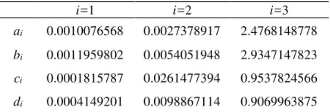
Calculate the rotation angle through two points at the origin and end of tunnel point clouds from the experimental section and then to coordinate rotate making the direction of X axis approximately parallel with tunnel’s direction; Fitting quadratic curves with the edge points based on the laws of above where parameter L is equal to 20mm, finally the average of this two quadratic curve is the tunnel axis (as shown in Fig.5 and Table 1).
(a) axis projected to XOY (b) axis projected to YOZ
Fig.5 Tunnel central axis of fitting
i=1 i=2 i=3
ai 0.0010076568 0.0027378917 2.4768148778
bi 0.0011959802 0.0054051948 2.9347147823
ci 0.0001815787 0.0261477394 0.9537824566
di 0.0004149201 0.0098867114 0.9069963875
Table 1. Parameters of quadratic curve
3.2 Parameter Selection of Elliptic Cylinder Model
There are two kinds parameters in the ellipse cylindrical model: (1) the interval d of the point cloud segmentation, this the segmentation parameter; (2) the iterative parameter K. Two types of parameters influence finally filtering effect,taking T as select evaluation parameters which is the division of M the remaining points after the non point filter and N the total points before filter,d and K should meet the largest value of T, which means non-points minimum and normal points maximize in the situation of no noise.
100% N M
T (15)
3.2.1 Segmentation Parameters on Filtering: It's need to choose reasonable parameters d to segmentation tunnel point cloud by the fitting axis, if d is large, the cross-sectional area will have a bigger difference with elliptic cylinder model and influence the filtering effect; when d is small,the computation time will increase. Taking into account the actual tunnel segment width is about 1.0m, six situation such as 0.2m, 0.4m, 1.0m, 2.0m, 3.0m, 4.0m were selected for filtering experiment (K=20mm) , the effect were shown in Fig.6. Table 1 lists the M and T in the above cases.
(a) d0.2m (b) d0.4m (c) d1.0m
(d) d2.0m (e) d3.0m (f) d4.0m Fig.6 Filtering effect diagram with different width
region(K=20mm)
d/m 0.2 0.4 1.0
M 1057733 1043746 1030129
T 79.83% 78.78% 77.75%
d/m 2.0 3.0 4.0
M 1028225 1025364 1015021
T 77.61% 77.39% 76.61%
Table 2. Filter results with different width region(K=20mm)
As Fig.6 and Table 2 shown, whend1.0m,there are still a large number of non-points in the tunnel support and orbital plane, the reason is that much non-points will effect the ellipse filtering in some region when d is small. At the time of
m
d1.0 ,the non-points can effectively filtered out, but with the increase of d, T gradually decrease, that’s suggesting when d is too large, there will be much normal points were filtered, so the appropriate segmentation parameter d is 1.0m or 2.0m.
3.2.2 Iterative Parameters on Filtering: The segmentation points iterative filtering based on2 principle, if lacking the
number of iterations, non-points will not be completely filtered out; conversely, it will filter normal points. It’s analysis of the influence of iterative parameter K on the filtering results (d=1.0m). Fig.7 is the filtering result in six situations when K equals 5mm, 10mm, 15mm, 20mm, 25mm and 30mm, table 2 lists M and T at the above cases.
(a) K5mm (b) K10mm (c) K15mm
(d) K20mm (e) K25mm (f) K30mm Fig.7 Filtering with different iterative parameters(d=1.0m)
K/mm 5 10 15
M 1006062 1021502 1029631
T 75.93% 77.71% 77.75%
K/mm 20 25 30
M 1030129 1085761 1111133
T 77.75% 81.95% 83.86%
Table 3. Iterative filtering with different parameters(d=1.0m)
From Fig.7 and table 3 can be seen that T is increases with the increase of K; when K is large, such as 25mm and 30mm, non-points can not be filtered completely; when K equals 10mm, 15mm, 20mm, Tis larger and stably in the vicinity of 77.7% and this is the optimal iterative parameter.Table 4 shows the long and short axis of consecutive fitting ellipse.
no. a/m b/ m no. a/m b/ m
1 2.712 2.686 7 2.706 2.687
2 2.706 2.690 8 2.705 2.693 3 2.707 2.683 9 2.706 2.689 4 2.704 2.678 10 2.706 2.690 5 2.703 2.683 11 2.708 2.690 6 2.706 2.682 12 2.706 2.681
Table 4. The long and short axis of fitting ellipse(d=2.0m)
(a) Tunnel points before filtering.
(b) Tunnel points after filtering.
Fig.8 Tunnel filtering and localize amplification
Fig.8 shows the effect of filtering when d=1.0m and K=20mm. Through the localized amplification can be seen both a variety of support tunnel wall and bolt slots between the adjacent tunnel segment have been filtered effectively.
3.3 Deformation Monitoring
(a) origin points of No.1 (b) origin points of No.2
(c) No.1 after filtering (d) No.2 after filtering
Fig.9 Tunnel Point cloud filtering
Build the digital surface model(DSM) using different stages of tunnel points after filtering based on software Geomagic Studio, then different orders of deformation region can be obtained by DSM. Fig. 9 (a), (b) is the same region interval 120 days, after the elliptical cylinder model filtering are shown in Fig. 9 (c), (d), the two phases of points are converted to the same coordinate system by the standard target.
Using Geomagic Studio for the filtering of the two point cloud respectively, such as the operation of the hole filling processing, get the DSM as shown in Fig. 10 (a), (b) as shown in Fig. 10 (c) for the two phases of the DSM overlay display. When analysis tunnel changes, the first period DSM was used as reference and the second period DSM expansion outward and contraction inward along tunnel normal respectively, the different order magnitude of deformation zone is detected by the value of
. Fig. 10 (d), (e), (f) is the second period DSM expansion outward of 3mm, 5mm and 10mm; Fig. 10 (g), (h), (i) is the second period DSM contraction inward of 3mm, 5mm and 10mm.(a) DSM of no.1 (b) DSM of no.2 (c) overlay DSM
(d) 3mm (e) 5mm (f) 10mm
(g) 3mm (h) 5mm (i) 10mm Fig.10 Analysis of tunnel deformation
Fig. 10 (d) in the gray area and Fig. 10 (g) in the red area suggest this region of tunnel’s variable is more than 3mm; Fig. 10 (e) in the gray area and Fig. 10 (h) in the red area suggest this region of tunnel’s variable is more than 5mm; Fig. 10 (f), (I) shows that the tunnel deformation is less than 10mm.
4. CONCLUSIONS
According to the distribution characteristics of subway tunnel non-points, this paper has proposed a filtering method using ellipse cylinder model, which include the tunnel axis extraction, point cloud segmentation and elliptic cylindrical fitting, analysis the selection of parameters in the model through experimental. In summary,in the application of tunnel deformation monitoring, there are 3 conclusions as follows: 1)elliptic cylindrical model can effectively filter the tunnel non-points; 2)the best segmentation parameter is close to the tunnel segment width; The International Archives of the Photogrammetry, Remote Sensing and Spatial Information Sciences, Volume XLI-B1, 2016
3)the method can be used for deformation monitoring of the tunnel and obtained different orders of deformation region using DSM.
With the increasingly application of 3D laser scanning technology in subway tunnel, the filtering method can provide reference for tunnel modeling, deformation monitoring and so on, but for the parameters’ adaptive selection in the model remain to further research.
ACKNOWLEDGEMENTS
Work described in this paper was jointly supported by Road traffic in the field of civil military integration demonstration projects(GFZX0404080102).
REFERENCES
Anne Griebel, Lauren T. Bennett, Darius S. Culvenor, et al, 2015. Reliability and limitations of a novel terrestrial laser scanner for daily monitoring of forest canopy dynamics, Remote Sensing of Environment, 166(1), pp. 205-213.
Ahlem Othmani, Lew F.C. Lew Yan Voon, Christophe Stolz, et al, 2013. Single tree species classification from Terrestrial Laser Scanning data for forest inventory, Pattern Recognition Letters, 34(16), pp. 2144-2150.
Bisheng Yang, Zhen Dong, 2013. A shape-based segmentation method for mobile laser scanning point clouds, ISPRS Journal of Photogrammetry and Remote Sensing, 81, pp. 19-30.
Brian M. Wing, Martin W. Ritchie, Kevin Boston, et al, 2015. Individual snag detection using neighborhood attribute filtered airborne lidar data, Remote Sensing of Environment, 163(15), pp. 165-179.
C. Cabo, C. Ordoñez, S. García-Cortés, et al, 2014. An algorithm for automatic detection of pole-like street furniture objects from Mobile Laser Scanner point clouds, ISPRS Journal of Photogrammetry and Remote Sensing, 87, pp. 47-56.
Cheng-Wei Kuo, Gary Brierley, Yo-Ho Chang, 2015. Monitoring channel responses to flood events of low to moderate magnitudes in a bedrock-dominated river using morphological budgeting by terrestrial laser scanning, Geomorphology, 235(15), pp. 1-14.
Chuanfa Chen, Yanyan Li, Wei Li, et al, 2013. A multiresolution hierarchical classification algorithm for filtering airborne LiDAR data, ISPRS Journal of Photogrammetry and Remote Sensing, 82, pp. 1-9.
Domen Mongus, Borut Ž alik, 2012. Parameter-free ground filtering of LiDAR data for automatic DTM generation, ISPRS Journal of Photogrammetry and Remote Sensing, 67, pp. 1-12.
Ee Hui Lim, David Suter, 2009. 3D terrestrial LIDAR classifications with super-voxels and multi-scale Conditional Random Fields, Computer-Aided Design, 41(10), pp. 701-710.
Gabriel Walton, Danielle Delaloye, Mark S. Diederichs, 2014. Development of an elliptical fitting algorithm to improve change detection capabilities with applications for deformation
monitoring in circular tunnels and shafts, Tunnelling and Underground Space Technology, 43, pp. 336-349.
Jixian Zhang, Xiangguo Lin, 2013. Filtering airborne LiDAR data by embedding smoothness-constrained segmentation in progressive TIN densification, ISPRS Journal of Photogrammetry and Remote Sensing, 81, pp. 44-59.
Luca Penasa, Marco Franceschi, Nereo Preto, et al, 2014. Integration of intensity textures and local geometry descriptors from Terrestrial Laser Scanning to map chert in outcrops, ISPRS Journal of Photogrammetry and Remote Sensing, 93, pp. 88-97.
Marko Pejić , 2013. Design and optimisation of laser scanning for tunnels geometry inspection, Tunnelling and Underground Space Technology, 37, pp. 199-206.
Ramón Argüelles-Fraga, Celestino Ordóñez, Silverio García-Cortés, et al, 2013. Measurement planning for circular cross-section tunnels using terrestrial laser scanning, Automation in Construction, 31, pp. 1-9.
Timothy Nuttens, Cornelis Stal, Hans De Backer, et al, 2014. Methodology for the ovalization monitoring of newly built circular train tunnels based on laser scanning: Liefkenshoek Rail Link (Belgium), Automation in Construction, 43, pp. 1-9.
Waldemar Kociuba, Waldemar Kubisz, Piotr Zagórski, 2014. Use of terrestrial laser scanning (TLS) for monitoring and modelling of geomorphic processes and phenomena at a small and medium spatial scale in Polar environment (Scott River —
Spitsbergen), Geomorphology, 212(1), pp. 84-96.
Weixing Wang, Weisen Zhao, Lingxiao Huang, et al, 2014. Applications of terrestrial laser scanning for tunnels: a review, Journal of Traffic and Transportation Engineering (English Edition), 1(5), pp. 325-337.
Xuelian Meng, Le Wang, José Luis Silván-Cárdenas, et al, 2009. A multi-directional ground filtering algorithm for airborne LIDAR, ISPRS Journal of Photogrammetry and Remote Sensing,64(1), pp. 117-124.
Yi Lin, Martin Herold, 2016. Tree species classification based on explicit tree structure feature parameters derived from static terrestrial laser scanning data, Agricultural and Forest Meteorology, 216(15), pp. 105-114.