www.adv-radio-sci.net/14/1/2016/ doi:10.5194/ars-14-1-2016
© Author(s) 2016. CC Attribution 3.0 License.
Concept and design of a UAS-based platform for measurements
of RF signal-in-space
Thorsten Schrader1, Jochen Bredemeyer2, Marius Mihalachi1, Jan Rohde1, and Thomas Kleine-Ostmann1 1Physikalisch-Technische Bundesanstalt (PTB), Braunschweig, Germany
2FCS Flight Calibration Services GmbH, Braunschweig, Germany
Correspondence to:Thorsten Schrader ([email protected])
Received: 15 January 2016 – Revised: 26 April 2016 – Accepted: 17 May 2016 – Published: 28 September 2016
Abstract. Field strength or signal-in-space (SIS) measure-ments have been performed by using manned helicopters, air-crafts or from ground level using extendable masts. With the availability of unmanned aerial systems (UAS) such as mul-ticopters a new versatile platform for SIS measurements is deployable. Larger types show up to eight individually driven electric motors and controllers (therefore called octocopter). They provide the ability to fly along predefined traces, to hover at waypoints and to initiate other actions when those have been reached. They provide self-levelling and stabilisa-tion and moreover, they may gear at a point of interest regard-less of their actual position, e.g. during their flight around a tower. Their payload mainly depends on the platform size and allows integration of complex measurement equipment. Upgrading their navigation capabilities including state-of-the-art global navigation satellite system (GNSS) and ground station transmitter (real-time kinematic – RTK) enables pre-cise localisation of the UAS. For operation in electromag-netic harsh environments a shielding can be considered and integrated into the concept.
This paper describes concept and design of an octocopter and its instrumentation, along with applications in recent projects, in which we measure and validate terrestrial nav-igation systems applied in air traffic and the weather forecast services. Among those are instrumentation landing systems (ILS), VHF omnidirectional radio ranges (VOR), airport traf-fic and weather radars as well as military surveillance radars, and UHF wind profilers. Especially to investigate the possi-ble interaction of VORs and radars with single wind turbines (WT) or wind power plants has become a major request of economy, military and politics. Here, UAS can be deployed to deliver measurement data investigating this interaction. Once developed and setup to a certain extent, UAS are easy
and cost-efficient to operate. Nonetheless, due to their com-pact size, UAS will have rather low interaction with the elec-tromagnetic field to be measured compared to the operation of manned helicopters.
1 Introduction
sys-2 T. Schrader et al.: Concept and design of a UAS-based platform for measurements of RF signal-in-space tems (ILS) is of interest (primary the localiser part), which
can not be assessed sufficiently by conventional flight in-spection (FI). In the second project (WERAN project, Ger-man abbreviation for “Measuring the potential interaction of wind turbines with terrestrial navigation and radar systems”, Schrader et al., 2015), supported by the Federal Ministry of Economic Affairs and Energy on the basis of a decision by the German Bundestag (grant: 0325644A), the potential interaction between wind turbines and terrestrial navigation systems and radar used in civil and military air traffic con-trol, weather radar and weather forecast wind profiler is in-vestigated. Therefore, the German Air Traffic and Naviga-tion Service Provider (Deutsche Flugsicherung DFS GmbH) and the German Weather Service (Deutscher Wetterdienst, DWD) are unfunded partners in the WERAN project. To-gether with funded partners, the Institute for Foundations of Electrical Engineering and Measurement Technology, Leib-niz University of Hanover, Germany, and steep GmbH, Bonn, Germany, we conduct the WERAN project.
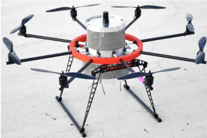
Rather than developing the octocopter from scratch, a commercially available platform “ARF-OktoXL” from HiSystems GmbH, Moormerland, Germany (http://www. mikrokopter.de), has been chosen and customised according to our needs (Fig. 1).
The manufacturer also provides a convenient GUI (cp. Fig. 2) to setup the UAS (check motor controls etc.) and the measurement campaign including the GNSS based flight track, way points, points of interest, etc. (see Sect. 2 for more information).
Our main focus is to make latest multicopter technology available for the precision measurement of electromagnetic fields.
When starting the UAS research program “ARCASS” (ad-vanced remote-controlled airborne sensor system) in our de-partment of High Frequency and Fields, we already had ex-perience in the operation of remotely controlled model he-licopters of bigger size (1.6 m rotor diameter). Seen from the retrospective, our experiences with helicopters helped to some extent to safely operate the octocopter during the exper-imental setup. It has to be noted here that pilots shall apply for an official permit issued by the Federal State Authority for Traffic to operate any sort of UAS, regardless of their commercial or scientific usage. The flight skills of the pilot are assessed by the local authorities. Moreover, the owner of the ground has to give his agreement for start and land-ing on his premises. Other official rules may apply for flight paths, maximum heights, areas etc. Local regulations must be obeyed.
In Sect. 2 we describe the design principles of the fly-ing platform. Both the RF instrumentation and the improved GNSS receiver on-board are given in Sect. 3. In Sect. 4 we present first measurement results as prof-of-concept.
Figure 1.Photograph of electromagnetically shielded octocopter.
2 Design of flying platform
ARCASS always uses a standard flying platform (UAS) with advanced precision localisation (Mihalachi et al., 2015). However, dependent on the task, the instrumentation, namely the sensor head, is exchanged. The sensor head consists of receiving antenna and RF frontend with up to three coherent channels. Each sensor head is specifically designed for the desired frequency band and task. The sensor system consists of multiple sensor heads that can be operated consecutively one after another (but not in parallel) whereas the data sam-pling and recording unit is kept unchanged at any time.
A quick-lock system is used, on the one hand ensuring a fast exchange of the different heads, and on the other, to pro-vide a consistent orientation of the sensors with respect to the UAS. This is a primary condition to be fulfilled in order to assign calibration factors to the whole setup consisting of sensor head and UAS. A second condition is based on the ability of the UAS, to always “face” a predefined point of in-terest. As an example, we discuss the measurement of an an-tenna pattern of a broadcast tower. When the UAS is orbiting the antenna mast at constant height, the UAS simultaneously rotates around its vertical axis with regard to the actual po-sition instead of maintaining a constant yaw angle. By this procedure the receiving antenna pattern of the UAS remains almost constant, of course with some uncertainty.
2.1 Mechanical setup and EMC considerations
Figure 2.Screenshot of GUI for campaign planning.
Figure 3.Mechanical setup of the UAS with the battery tray opened.
the yaw angle, but will also interfere with the fields to be measured, especially at frequencies up to a few hundreds of MHz. On the other hand, we plan to fly in electromagnetic harsh environments. Therefore, shielding against high power RF external sources is necessary to protect the UAS itself. Of course, shielding against external RF radiation will also reduce the emissions from the UAS itself. Since payload is always limited on flying platforms, the shielding has to be of light weight. To reach the defined safety limits, all electronic instrumentation need to be encapsulated by the shielding,
in-cluding motor controllers, flight controller, navigation con-troller, data sampling and storage unit, etc. To prevent over-heating of the electronics inside, a mesh shielding has been designed that allows for some air flow through it. Another ad-vantage of the mesh shielding is that the internal barometric pressure sensor of the UAS contributing to the height infor-mation relative to the ground level is not affected.
4 T. Schrader et al.: Concept and design of a UAS-based platform for measurements of RF signal-in-space
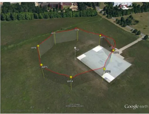
Figure 4.Flight track with waypoints (WP) and point of interest (POI).
outer body of the shielding that takes all of these conditions into account. The top plate also serves as mounting pad for the different sensing heads and the GPS antenna. The in-ner part of the bottom plate can be unlocked and released, thereby giving access to the battery compartment. The outer ring of the lower plate serves as support for the antenna of the remote-control receiver, the downlink for the flight status to be received by a smartphone application, and the uplink for the RTK correction signal. All input and output signal paths are filtered using narrowband bandpass filters.
For simplicity reasons, the sensing head is typically mounted on top of the UAS, which moves the center of gravity of the UAS. Test flights with simple ballast instead of the electronics have shown, that the UAS can handle its payload even in windy conditions. The octocopter setup seems to be more stable compared to UAS configured with a smaller number of motors/propellers, especially in case of motor/controller failure. For some applications, e.g. when the measurement signal directly comes from “down under” the sensor is mounted underneath the UAS, using an updated cal-ibration factor.
2.2 Precision navigation using RTK
One of the advantages of UAS is their ability to approach predefined waypoints (WP) (cp. Fig. 4), a locus in space (WGS84 format and height above ground – not absolute height), and to trigger some action when the WP has been reached. In our case, these WP are defined using the soft-ware MK-tool provided by HiSystems GmbH (Fig. 2). The
Figure 5.Repeated flight pattern using the same flight track with standard single frequency GPS receiver u-blox LEA 6S.
to 10 m (cp. the red circles in Fig. 5). When the UAS real-ized that the WP has been reached, it hovered there for 10 s and then continued its flight to the next WP. The time needed to catch the WP was almost negligible. Next, we have de-creased the WP to 3 m. It took the UAS quite a while (about 15 s) to recognise the actual position being located inside the waypoint radius though it did not change its position. Fur-ther reduction of the WP radius caused the octocopter to stay at its position trying to reach the first WP. Especially under windy conditions and with high payload this localisation was not acceptable.
In order to be able to reduce the waypoint radius with-out sacrificing the time to reach the desired WP, the single frequency GPS receiver u-blox LEA 6S was removed and replaced by a OEM615 (NovAtel, 2013), which is a state-of-the-art dual frequency airborne receiver. Its update rate for the actual position is improved to 20 Hz compared to 5 Hz before. Some additional hardware had to be designed in or-der to integrate the new receiver with the existing electronics (Fig. 6). Because u-blox and NovAtel use different protocols for transmitting the actual position information, the software of the navigation controller was also modified to accommo-date a new protocol parser. Besides the signals from GPS and GLONASS satellites the NovAtel receiver uses additional differential correction data in RTCA or RTCM format from a NovAtel ground station (receiver model OEM628; NovAtel, 2013). The latter acquires samples from the GNSS satellite information for a long observation time, e.g. 24 h or even more. This significantly reduces the uncertainty of the po-sition of the ground station receiver, until it has reached a
Figure 6.Connector board between NovAtel receiver, radio mo-dem, and UAS.
Figure 7.Standard deviation of the NovAtel ground station receiver position.
lateral uncertainty of position of a few cm and a height accu-racy of better than 10 cm (Fig. 7). From this known position and the actual GNSS information the ground station receiver calculates the offset and transmits the error correction using a radio link with an update rate of 1 Hz. The onboard receiver of the UAS takes this correction signal together with the ac-tual GNSS data to calculate the updated position as input for the navigation controller of the UAS.
A test of the NovAtel ground station and a stationary op-erated UAS showed the drastic improvement in localisation close to the theoretical limit. Further tests with payload and under windy conditions will reveal the practical limit of the advanced positioning.
6 T. Schrader et al.: Concept and design of a UAS-based platform for measurements of RF signal-in-space
Figure 8.Block diagram of the RF frontend.
3 The instrumentation and data processing unit 3.1 RF front-ends and antennas
As already mentioned, the applications for the UAS-based platform are quite versatile including the measurement of ra-dio frequency (RF) signals. For every application different RF frontends will be developed, which can be connected to the data processing unit using the same interface (Fig. 8). Until now, a superheterodyne receiver design is used (Pozar, 2005). All receivers provide a 50input connector for the antenna. The RF signal is amplified, filtered and downcon-verted to an intermediate frequency (IF) of 70 MHz using a local oscillator signal from the data processing unit. The IF signal is then filtered by a Surface-Acoustic-Wave (SAW) fil-ter, to suppress undesired mixing products and adjacent RF-channels. The IF-signal is amplified and can be measured at a 50output port. The IF signal is sampled and stored by the data processing unit using a fast analog-to-digital converter (ADC) and a solid-state hard disc as mass storage device. To obtain a higher dynamic range a variable gain amplifier (VGA) is used as an IF amplifier (DVGA2-33+from Mini-Circuits, http://www.minicircuits.com). The gain can be con-trolled by the data processing unit via a serial interface. To determine the correct gain, the IF power is measured after the IF filter using a logarithmic amplifier with demodulation (AD8307 from Analog Devices, http://www.analog.com). The device delivers a DC voltage that is proportional to the logarithm of the input voltage level, which then can be mea-sured by the data processing unit using an ADC. Until now, highly integrated amplifiers are used for the receiver provid-ing high gain, low noise figure, and high bandwidth (Fig. 9). Additionally, the receivers design can easily be adapted for new applications. Only a few frequency dependent compo-nents like the input and IF filters need to be replaced. How-ever, the power consumption of approx. 300 mW for each receiver is relatively high.
As an example the electrical field strength in free space can be measured by calibrating the whole system, including
Figure 9.Photograph of one receiver channel board.
the antenna, the RF frontend, and the data processing unit, in a known electrical field.
The data processing unit is capable to sample up to 3 re-ceived signals simultaneously. Therefore, the electrical field vector can be calculated measuring the field strength of 3 probes where each probe is sensitive for one field component in an orthogonal system. Of course, scalar or 2-dimensional measurements are also possible. A variety of linear anten-nas has been developed for different frequencies and appli-cations. Measurements have been performed with passive dipoles, active dipoles, passive bowtie antennas and passive monopoles. Because of the limited space on the UAS, elec-tric small antennas are preferred to detect electromagnetic waves up to 1 GHz. For simplicity, the radiation pattern of each antenna should be as close as possible to an ideal, elec-trical short, linear antenna (Balanis, 2005). Since the radia-tion pattern is not ideal, a model for real antennas has been developed. The signal of the real antenna is modelled as a superposition of the signals of an ideal isotropic and an ideal linear antenna. The parameters for this model are again de-termined through calibration in a known electrical field. 3.2 Data acquisition and processing
It is the task of the data acquisition board to control the re-ceiver frontend and to pre-process and save the RF data on a suitable storage medium. Figure 10 gives an overview of the components.
An “Arria V” FPGA is the central design unit that controls all components and employs an embedded 32bit processor (Altera, www.altera.com). A coherent clock distribution fed by a stable temperature-controlled crystal oscillator (TCXO) drives all frequency-dependent components as local oscilla-tors (LO) and A/D converters. Three receivers can be con-nected that allow to measure the field polarisation with an orthogonal antenna-triple. The 16 bit-wide A/D converters have sample rates up to 160 MHz. That ensures to sample wideband signals of radar applications within WERAN.
Figure 10.Block schematics of data acquisition and signal process-ing board.
are fully coherent with AD sampling. That simplifies the RF frontends which hence do not need own LOs. Actually, the RF can be provided with two LO frequencies. This enables RF concepts with two intermediate frequencies (IF) which is useful at carrier frequencies of several GHz. The control board of each RF frontend also includes an automatic gain control (AGC) to adapt the RF signal strength to the ADC input. Variable gain amplifiers (VGA) are connected via a serial peripheral interface (SPI).
RF data acquisition is performed by direct IF sampling, i.e. a band pass signal (but not a baseband signal) is ob-tained. Any necessary signal pre-processing is carried out within the FPGA. However, it is the concept of the WERAN data processing that a nearly unaltered signal is stored on the octocopter platform to be analyzed by subsequent post pro-cessing. A high-bandwidth data recording is realized by im-plementing a SATA-IP (Serial ATA disk) core in the FPGA. It operates at SATA 3-speed (6 GBps) and allows the direct connection of a micro SATA solid-state disk (SSD). A LAN interface allows for the download of the measurement data after landing of the octocopter without removing the SSD from the UAS. The processor interfaces with the main octo-copter controller via an I/O interface. Optionally, it can use its on-board GNSS module to obtain time and position infor-mation.
3.3 Undersampling technique
A common misconception of the Nyquist criteria is that the sampling frequency must be twice the highest frequency present in the signal s(n). In fact, the sampling frequency needs to be only twice the signal bandwidth to prevent alias-ing:
fS>21f (1)
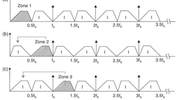
Undersampling is corresponding with the use of a sam-pling frequency which is less than the highest frequency present in the signal. In Fig. 11, from (Zumbahlen, 2008) this principle is illustrated in frequency domain. Signals below
Figure 11.Nyquist zones and frequency translation (Zumbahlen, 2008).
0.5fS are located in the so-called first Nyquist Zone (NZ), see panel a. Sampling these signals preserves their original carrier frequency. The number of NZ increments by every 0.5fS. Frequencies higher than half the sampling rate are folded back into the 1st NZ. Hence, a signal located in any higher NZ will give an image in the first NZ (panel b, c). No signal information is lost except for the value of the original carrier frequencyfC. An additional frequency reversal oc-curs, if signals are located in even Nyquist zones (panel b).
If equation
fS= 4fC
2NZ−1 (2)
applies, then the image offCis safely placed in the center of the first NZ (=0.25fS; Zumbahlen, 2008).
Then the primary function of an anti-aliasing filter is to ensure that the band of sampled signals must not overlap any multiple offS/2, i.e. it is limited to a unique Nyquist zone. In the WERAN RF frontend designs a steep band pass filter is placed in the IF section. The VOR RF frontend offers a 70MHz IF. After further amplification on the digitizer board, this signal is then initially sampled at 105 MHz. This converts the IF into the second NZ, resulting in an image in first NZ at 35 MHz. A chain of FIR (Finite Impulse Response) dec-imation band pass filters inside the FPGA then reduces the sampling rate dramatically, but finally it remains well above twice the channel bandwidth of 25 kHz when stored on the SSD.
4 First measurements
am-8 T. Schrader et al.: Concept and design of a UAS-based platform for measurements of RF signal-in-space
Figure 12. Bandpass signal of received DVOR “HLZ” at 117.3 MHz; static measurement on PTB premises at a distance of about 23 km to the DVOR (measurement antenna located at the Willy-Wien tower about 40 m above ground level).
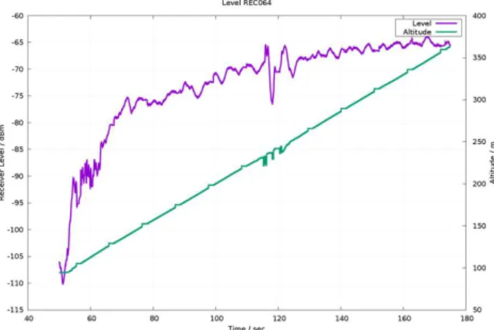
Figure 13.Measured receiver level of DVOR Wolfsburg-Hehlingen (Germany) as a function of altitude.
plitude band pass samples gives a spectrum normalized to the carrier frequency (Fig. 12).
In the first measurement campaign the DVOR “HLZ” in Wolfsburg-Hehlingen, Germany, was investigated. As an ex-ample for the data obtained, Fig. 13 shows a cut-out of the measured receiver level as a function of altitude. After au-tomatic start, the octocopter was programmed to constantly increase its altitude up to 500 m at 2.5 m s−1 speed. The platform maintained that position for 30 s, followed by the automatic decay down to 30 m altitude, again at constant 2.5 m s−1 speed. Landing is typically performed by manual maneuvers. Latitude and longitude were kept the same dur-ing the flight. The startdur-ing point was located about 5 km south of the DVOR in the open landscape, without any buildings, wind turbines etc. in the line-of-sight.
5 Conclusions
Design and concept of a new versatile and flying measure-ment platform used to perform precision measuremeasure-ments of electromagnetic signals in space are described. This
un-manned aerial system (UAS) is based on a commercially available octocopter. Its navigation and localisation capabil-ities were significantly improved by a state-of-the-art real-time kinematic receiver and a ground station transmitter, which delivers the correction signal for the actual GNSS signal. The on-board receiver utilises the actual GNSS sig-nal and the correction to determine an improved position in space, which is fed into the navigation and flight controller of the UAS. Automatic starts, flights along predefined tracks using waypoints, and automatic landing makes the UAS easy to operate. The alignment of the “front” direction of the UAS with respect to a point of interest allows the measurement of radiation pattern in space. With the availability of this UAS remote areas now become easily accessible, especially if an elongated observation time for measurements is needed. Flight costs are at low level. Flight time with one set of bat-teries is in the order of 30 min depending on the payload and the wind conditions. To fly in electromagnetic harsh environ-ments, a proper shielding of the electronics was considered and the final tests are underway. Heating up inside the shield-ing was avoided by usshield-ing a mesh cover. To ensure its proper operation, the main parameters of the UAS are transmitted and may be displayed on an Android-based smartphone.
A set of antennas and receivers is currently developed for each frequency band of interest, starting at the VOR frequen-cies of around 110 MHz. So far, the highest measurement fre-quency is 5.6 GHz (weather radars). The sensing heads are interchangeable using a lock to make the mounting position consistent and repeatable, thereby maintaining the validity of the calibration factors. Antenna calibration must be per-formed on the whole set consisting of the UAS and the sens-ing head. Straight forward superheterodyne receivers in the RF frontends feed the measurement signals into the FPGA-based sampling board. RF data acquisition is done by direct IF sampling, i.e. a band pass signal (but not a baseband sig-nal) is obtained. As the raw data are stored on a solid-state disk, all options are available for post-processing.
First measurement results indicate the expected perfor-mance and document the proof-of-concept.
Acknowledgements. The authors thank their partners within the WERAN project: Mr. Heyno Garbe and his team from the Leibniz University of Hanover (LUH), steep GmbH, as well as Deutsche Flugsicherung, Deutscher Wetterdienst, and Bundesaufsichtsamt für Flugsicherung for continuing support and discussion.
Edited by: T. Probst
References
Balanis, C. A.: Small Dipole, in: Antenna Theory, 3rd Edn., Hobo-ken NJ, John Wiley & Sons Inc., 2005.
Mihalachi, M., Schrader, T., Rohde, J., and Kleine-Ostmann, T.: UAV-Based Measurement Platform for Precision Electromag-netic Field Measurements, 2015 IEEE International Symposium on Electromagnetic Compatibility (EMC), WS14 Unmanned Aircraft Systems – EMC and Applications, Dresden, Germany, 16–22 August, 2015.
Morgan-Owen, G. J. and Johnston, G. T.: Differential GPS position-ing, Electron. Commun. Eng., 7, 11–21, 1995.
NovAtel: Positioning Modes of Operation, Application Note, Rev. 1, http://www.novatel.com/assets/Documents/Bulletins/apn051. pdf, 24 October 2013.
Pozar, D. M.: Radio Receiver Architectures, in: Microwave Engi-neering, 3rd Edn., John Wiley & Sons Inc., 2005.
Schrader, T., Bredemeyer, J., Stupperich, C., and Garbe, H.: WERAN – Interaction of Wind Turbines with Terrestrial Navi-gation/Radar Systems, 2015 IEEE International Symposium on Electromagnetic Compatibility (EMC), WS14 Unmanned Air-craft Systems – EMC and Applications, Dresden, Germany, 16– 22 August, 2015.
Shao, M. and Sui, X.: Study on Differential GPS Positioning Meth-ods, 2015 International Conference on Computer Science and Mechanical Automation (CSMA), 23–25 October 2015, 223– 225, 2015.