International Journal of Engineering and Technology Volume 2 No. 12, December, 2012
ISSN: 2049-3444 © 2012 – IJET Publications UK. All rights reserved.
1991
Contact Stress Analysis around Elliptical Bolt-loaded Hole in
Orthotropic Plates
O. Aluko
1, S. T. Adedokun
2, T. A. Fashanu
31
Department of Mechanical Engineering, University of Michigan, Flint, Houghton, Michigan, USA 2
Department of Mechanical Engineering, Covenant University, Canaanland, Ota, Nigeria 3
Department of Systems Engineering, University of Lagos, Akoka-Yaba, Lagos, Nigeria.
ABSTRACT
The practicality of changing the bolt shape from circular to elliptical under friction effects in order to reduce the contact stress distributions was analytically investigated. The analysis utilized the complex stress functions obtained from the assumed displacement expressions that satisfy the boundary conditions around the hole to determine the contact stresses. In the method of solution coulomb friction was used to determine the prescribed displacements at the boundary. The material properties of graphite/epoxy and carbon fiber reinforced plastics laminates were used in this investigation and the results compared with available literature. It was revealed that the stress distributions followed the same pattern in both geometries but with lower magnitude in elliptical shape and the reduction in stress distributions caused by changing the bolt shape from circular to elliptic depend on friction coefficient.
Keywords: Circular, Elliptic, Contact stresses, Frictional effects, Stress functions
1.
INTRODUCTION
Composite materials have been widely used in aerospace structures, space vehicles and many other engineering structures in recent years due to their high specific strength and stiffness. However, the joints often required for fitting composite parts usually constitute region of weakness which can lead to premature failure of structures. Out of the two methods frequently used, mechanical joints offer the advantage of assembly and disassembly over adhesive joints. Hence, the analytic determination of mechanical joint strength has attracted the attention of many investigators, these include; Ryu et al. (2006) and Zhang and Ueng (1984). In addition, Whitworth et al. (2008) and Madenci et al. (2001) were also involved with the problem of providing solution to premature joint failures.
Wang et al. (1993) investigated the possibility of changing the bolt and hole shapes from conventional circular shape to elliptical in order to reduce bearing stress, and thereby increase the joint strength especially when it is not possible to increase the hole diameter due to insufficient edge distance but with an acceptable distance between the bolts. Their analysis showed that the bearing stress at the joint hole can be significantly reduced by changing the bolt shape to elliptical.
The present study utilized an alternative method to further investigate how the reduction in contact stresses caused by changing the bolt shape can be influenced by friction at the contact surfaces between the bolt and composite plate since friction cannot be totally eliminated between
the two contacting surfaces under practical situation. Thus, an analytical method that involved the determination of exact complex functions that are used to calculate the stress distributions around the contact hole boundary. The underlying assumption is that displacement expressions meet the boundary conditions within the contact region. In addition, the interaction among contact stresses at different values of coefficient of friction was investigated and numerical solutions for the case of elliptical and circular pin are presented.
2.
ANALYTICAL METHOD
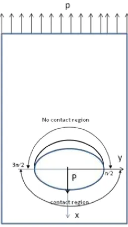
The geometry of the composite plate loaded by an elliptical pin is shown in Figure 1. The origins of the Cartesian coordinate system (x, y) and polar coordinate
system (r, ) employed in this analysis coincide with the center of the bolt-loaded hole . The semi minor and major axes of the elliptical hole are denoted by a, and b
respectively and the hole contour is described by x = aCos and y = bSin . The clearance between the elliptical pin and hole is zero, the pin is assumed to be rigid since pin flexibility is not one of the significant variables in finding the contact stresses; Eriksson and Aronsson (1990), Hyer and Klang (1985) and Persson and Madenci (1998).
The plate is assumed to be infinite and its principal material axes are in x- and y-axes. The pin is considered to be acted on by a resultant force P causing displacement
ISSN: 2049-3444 © 2012 – IJET Publications UK. All rights reserved.
1992
direction of loading increases. For the linear case of zero clearance, contact between the plate and the pin spans
through half of the hole’s circumference and no-slip region within the contact surface is assumed to act at a
point since this has been found to be equal to zero, De Jong, (1982) and Aluko (2007). The boundary conditions for the geometry shown in Figure 1 can be stated as follow:
Region I (Contact region): 3/ 2/ 2
0
v
andu
c
o ;
0
(1)r
rr ;
0
(2)1
u
c
and
v
0
;
/ 2, 3 / 2
(3)(
c
o
u
) cos
v
sin
;
3 / 2
/ 2
and
0
(4)rr r
;
3 / 2
and
/ 2
(5)Region II (No contact region):
/ 2
3 / 2
0
0
/ 2
3 / 2
rr
r
(6)For the case of generalized plane stress with anisotropic materials, Lehknitski (1968) has shown that the stress function F, that satisfies the equilibrium and compatibility
conditions, will meet the generalized biharmonic equation expressed in equation 7 as
4 4 4 4 4
22 4
2
26 3(2
12 66)
2 22
16 3 11 40
F
F
F
F
F
a
a
a
a
a
a
x
x y
x y
x y
y
(7)However, for the orthotropic plate in which the directions of the x and y axes coincide with the principal material direction, a16 and a26 are both zero and the characteristics of Equation 7 reduces to
4 2
11
(2
12 66)
220
a
a
a
a
(8)
The stresses and displacement can be expressed as
2 ' 2 '
1 1 1 2 2 2
' '
1 1 2 2
' '
1 1 1 2 2 2
2 Re
( )
( )
2 Re
( )
( )
2 Re
( )
( )
x y xy
z
z
z
z
z
z
(9)
1 1 1 2 2 2
1 1 1 2 2 2
2 Re
( )
( )
2 Re
( )
( )
u
p
z
p
z
v
q
z
q
z
(10)where,
1
1 1
1
( )
z
dF
dz
, and 2 2 22
( )
z
dF
dz
(11)' 1
1 1
1
( )
z
d
dz
, and 2' 2 22
( )
z
d
dz
(12)1 1
;
2 2,
z
x
y z
x
y
and
1 and
2 are roots of characteristics equation 21 11 1 12 16 1
p
a
a
a
p
2
a
11
22
a
12
a
16
222
1 12 1 16
1
a
q
a
a
, and 2 12 2 22 262
a
q
a
a
(13)ISSN: 2049-3444 © 2012 – IJET Publications UK. All rights reserved.
1993
The displacements
u
andv
that satisfy the boundary conditions in the contact region can be expressed by the following trigonometry functions.
Where
U
1,
U
2,
V
1 andV
2 are coefficients to be determined from the boundary conditions.1 2
1 2
cos 2
cos 4
sin 2
sin 4
u
U
U
v V
V
(14)These coefficients are found by substituting equation (14) into boundary conditions defined by equations (1), (3) and (4) to yield
0 1 0 1
1 2
0 1 0 1
1 2 ; 2 2 3 ; 2 2
c c c c
U U
c c c c
V V (15)
Lekhnitski (1968) has shown that if the known boundary displacement at the contour of the opening can be expressed in the form
* 1 * 1 m mo m m
m
m m
o m m
m
u
v
(16)and the components of the resultant forces that cause the displacement are given, then the stress functions can be expressed by the following relations
1 1 1 1 2 1 2 2 2 2 2 1
2 1
2 2 2 1 1 1 1 1 1 1 1 2
2 2
1
1
1
( )
ln
(
)
(
)
2
1
1
1
( )
ln
(
)
(
)
2
m m m m m m m mz
A
q
p
ibq
ap
q
p
D
D
z
B
q
p
ibq
ap
q
p
D
D
(17)In Equations (16) and (17),
e
i and bars represent conjugate values. Similarly,
mand
mare known coefficients that depend on the load distribution at the opening edge.
o,
0 are arbitrary constants andD
,
p1, p2, q1 and q2 are constants that depend on the property of the plate. Also
k is the mapping function given by2 2 2
k k k
k
k
z
z
a
b
a i
b
k=1, 2 (18)similarly in equation (18),
k(k = 1,2) are the roots of characteristics equation (8). In addition, according to Madenci (2001), the constants A and B of equation (17) can be obtained from the following relations;12
1 1 1 2 1 2 1 2 1 2
22
1 1 1 2 1 2
12
2 2 2 1 2 1 1 2 1 2
22
2 2 2 1 2 1
(
)
(
)(
)(
)
(
)
(
)(
)(
)
a
a
P
A
ih
a
a
P
B
ih
(19)As previously indicated bars retain the definition of conjugate values. aij are the laminate elastic compliance and h is the thickness of the plate.
cos
2
n n
n
,
sin
2
n n
n
i
(20)Comparing equations (14) and (16), the stress functions of equation (17) can be expressed as
2 4
1 1 1 1 2 1 2 1 2 2 2 2 1
2 4
2 2 2 1 1 1 1 2 2 1 2 1 1
1
( )
ln
[
2
1
( )
ln
[
2
z
A
u q
iv p
u q
iv p
D
z
B
u q
iv p
u q
iv p
ISSN: 2049-3444 © 2012 – IJET Publications UK. All rights reserved.
1994
The radial, hoop and tangential stresses have been expressed in terms of the stress functions in Madenci
(2001). Thus we have
2 2
1 1 1 2 2 2
1 1 1 1
2 2 2 2
2 2
1 1 1 2 2 2
2 Re{(sin
cos )
( ) (sin
cos )
( )}
2 Re{(sin
cos )(cos
sin )
( )
(sin
cos )(cos
sin )
( )}
2 Re{(
sin
cos )
( ) (
sin
cos )
( )}
rr r
z
z
z
z
z
z
(22)Generally the derivative of the functions
1( )
z
1 and
2( )
z
2 are expressed as
2 4
1 1 2 2 2 2 1 2 1 2 1 2 2 2 2 1
1 1
2 4
2 2 2 2 2 2 1 1 1 1 2 2 1 2 1 1
2 2
1
1
2
( )
[
]
1
1
2
( )
[
]
z
A
u q
iv p
u q
iv p
D
D
z
a
b
z
B
u q
iv p
u q
iv p
D
D
z
a
b
(23)For the special case of a circular hole, semi axis a is equal to semi axis b in equation (23). At the boundary of the elliptic hole, equation (23) becomes;
1 1 1 2 1 2
1
2 2 2 2
2 2 1 1 1 1
2
2 1 2 1
1
( )
[
[
(cos 2
sin 2 )
( sin
cos )
2
(cos 4
sin 4 )]
1
( )
[
[
(cos 2
sin 2 )
( sin
cos )
2
(cos 4
sin 4 )]
i
z
A
u q
iv p
i
a
b
D
u q
iv p
i
D
i
z
B
u q
iv p
i
a
b
D
u q
iv p
i
D
(24)As mentioned previously, in this analysis it was assumed that the circular hole deforms as an ellipse due to application of bolt load. Consequently, the axis of the elliptical hole increases along the direction of loading. Thus, in order to meet this deformation profile without
conforming to the complexity of meeting condition specified in Equation 6, Zhang et al. (1984) carried out an analysis that yielded an additional term for hoop stress. This is expressed in equation (25) as
2 1
11 11 22
2 2
11 22 11 11
1
1
1
(
( (
)(
) cos
1
1
1
(
(1
)(
)) sin
)) /(
(1
) )
o
u k
k k
n
a
a
a a
k
n k
n
n
k
n a
a a
a
a
(25)Determination of c
0and c
1The real parts of equation (22) was taken in term of co and c1 after the substitution of equations (23) and (24) in
conjunction with the geometric parameters of the hole (a
ISSN: 2049-3444 © 2012 – IJET Publications UK. All rights reserved.
1995
determined by substituting real parts of equation (22) into equation (5) expressed in form of stress resultant as
2 2
0 0
rr
r
d
d
(26)For a known value of coefficient of friction and equation
(θ) at =90⁰. Once co and c1 are determined, the unknown coefficients from the real part of equation (22) can be obtained from equation (15). This analytical method utilized Coulomb friction and assumed coefficient of friction to be constant within the region of contact as can be seen from equations (5) and (26). The minor axis of the elliptic hole (which was equal to the diameter of the circular hole) and its major axis are 0.625 and 0.75 centimeters respectively. For comparison graphite/epoxy laminate,
[0 / 45 / 0 ]
sof thickness, h=0.1125cm and width 3.375cm was taken from Wang et al. (1993) was evaluated. Additionally, carbon fiber reinforced plastic laminate, [03/±45]s of thickness, h=0.1125cm with properties obtained from De Jong (1982) was also used to evaluate stress distributions for each joint configuration. The elastic constants for the two laminates used are given in Table 1.3.
RESULTS
The results for contact stresses are presented in this analysis for both circular and elliptical bolt joints for values of friction coefficient of 0.0, 0.2, and 0.4; and an applied load of 153.06kg for
[0 / 45 / 0 ]
splates. In these figures, because of symmetry considerations, the variations of contact stresses with circumferential location are plotted only for the range0
90
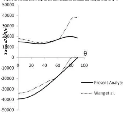
. Figures 2 and 3 showed the stress distributions at zero coefficient of friction in elliptical and circular bolt joints respectively. The distribution pattern for radial stress showed a good agreement with finite element method of Wang et al., (1993) with maximum peak stress occurring at = 0 in both configurations. Also, the hoop stress showed good correlation up to the neighborhood of =70⁰ beyond which certain differences do exist in both shapes. This difference might be caused by the difference in assumptions made on contact angle. Notwithstanding, both results predicted an increase in hoop stress due tochange of bolt shape near =90⁰. Figures 4 through 6 compare the stress distributions in
[0 / 45 / 0 ]
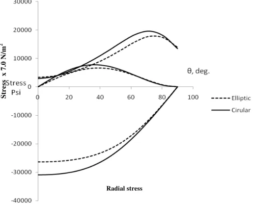
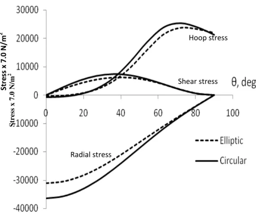
s plates for both circular and elliptical bolt shapes at different values of coefficient of friction. As can be seen in these figures, the pattern of contact stress distributions in both geometries is similar. For the case of radial stressdistribution, the magnitude of peak stress which is at =0 decreases with friction for both shapes. Additionally, as shown in Table 2 the percentage reduction in peak stress caused by changing the bolt shape from circular to elliptic decreases with increased coefficient of friction. The shear stress distribution showed similar pattern for both shapes with the peak stress occurring within the neighborhood of
=3θo
. The peak stress increases with friction in both geometries but with lower stress value in elliptical configuration. However, as can be seen in Table 2 the percentage reduction in peak stress value caused by the change in geometry for the case of shear stress increases with friction. It is also shown in Figures 4-6 the combine effect of bolt shape and friction on hoop stress distributions at the joint. Further, friction affects the hoop stress distribution just the same way in both geometries such that it is completely tensile for coefficient of friction
≤0.2 and initially compressive for =0.4 but become
progressively tensile at =27⁰. Additionally, as shown in Table 2 the percentage increase in peak hoop stress by changing the geometry of bolt from circular to elliptical as located within the neighborhood of =90o in Figures 4-6 increases with friction. Wang et al. (1993) also observed this increment.
The resulting stress distributions for the case of [03/±45]s
plate are presented in Figures 7 and 8 at =0.2 and 0.4. It
can be seen by comparison of these figures that friction affects contact stress distributions at the hole boundary for both shapes. Additionally, changing the shape of bolt from circular to elliptic reduces radial and shear stresses throughout the contact boundary and the percentage change in peak value of this reduction as shown in Table 2 depends on friction coefficient. However, for the case of hoop stress the reduction due to a change in bolt geometry did not occur throughout the contact boundary as an increase in hoop stress was observed within the neighborhood of =90⁰ and this percentage change in peak stress value, as shown in Table 2 increases with friction.
4.
CONCLUSION
The effect of bolt geometry in the presence of friction between the bolt and the orthotropic plate was evaluated in this investigation using graphite/epoxy plate [0 / 45 / 0 ] sand carbon fiber reinforced plastic plate
[03/±45]s. This analytical method showed that changing the bolt geometry from circular to elliptical reduces the radial and shear stress distributions for different values of coefficient of friction used and this reduction in stress value depends on friction between the contacting surfaces. Additionally, analytical results predicted a minor increase
ISSN: 2049-3444 © 2012 – IJET Publications UK. All rights reserved.
1996
good agreement with available finite element results in Wang et al. (1993).
REFERENCES
[1] Aluko O. A. (2007); compact analytical method for stress distribution in composite pinned joints. Ph.D. Thesis, Howard University
[2] De Jong T. (1982) Stresses around pin-loaded holes in composite materials. Mechanics of Composite Materials, Recent Advances. New York: Pergamon Press pp 339-353
[3] Eriksson L. I., and Aronsson C. G., (1990); On the strength of tensile loaded graphite/epoxy laminates containing cracks, open and filled holes. Journal of Composite Materials, Vol. 24:p457-482
[4] Hyer M. W., and Klang E. C., (1985); Contact stresses in pin-loaded orthotropic plates. International Journal of Solids and Structures. Vol. 21: p957-975
[5] Lehknitski S. G., (1968); Anisotropic plates. Translated from the 2nd Russian edition by Tsai SW, Cheron T. London:Gordon and Breach
[6] Madenci E., Barut A. and Nemeth M. P., (2001); A complex potential-variational method for stress analysis of unsymmetric laminates with an elliptical cutout. Journal of Applied Mechanics, Vol. 68, Issue 5; p731-739
[7] Persson E. and Madenci E.Composite laminates with elliptical pin-loaded holes. Engineering Fracture Mechanics1998; 61:279-295
[8] Ryu C., Choi J., and Kweon J., (2006); Failure load prediction of composite joints using linear analysis. Journal of Composites Part B: Engineering, Vol. 41; p865-878
[9] Wang J.T., Lotts C. G., and Davis D.D.,(1993);
Analysis of bolt-loaded elliptical holes in laminated composite joints. Journal of Reinforced Plastics and Composites, Vol. 12; p128-138.
[10]Whitworth H.A,, Aluko O., and Tomlinson N. A., (2008); Application of the point stress criterion to the failure of composite pinned joints. Journal of Engineering Fracture Mechanics, Vol. 75: p1829-1839
[11]Zhang K., and Ueng C. E. S., (1984) Stresses around a pin-loaded hole in orthotropic plates. Journal of Composite Materials,Vol.18:p433-446
Table 1. Laminate Properties [2, 5]
Laminate
[0 / 45 / 0 ]
s
[0 / 45 ]
3
sEx Msi 8.13638 10.7330 Ey Msi 6.43159 2.4650 Gxy Msi 2.38338 2.7550
νxy 0.319787 0.914
Table 2. Percentage reduction in peak radial and shear stress with corresponding increase in peak hoop stress
Laminate Η %reduction in radial peak stress
% reduction in shear peak stress
% increase in hoop peak stress near =90⁰
[0 / 45 / 0 ]
s 0.0 17.84 - 2.240.2 17.17 17.01 3.23
0.4 15.87 17.71 5.30
3
[0 / 45 ]
s 0.0 17.80 - 2.320.2 17.21 18.76 3.18
ISSN: 2049-3444 © 2012 – IJET Publications UK. All rights reserved.
1997
(a) (b)
Plate geometry Boundary region Figure 1: Plate geometry and regions within pin-plate geometry
S
tr
e
ss
x
7
.0
N
/m
ISSN: 2049-3444 © 2012 – IJET Publications UK. All rights reserved.
1998
Radial stress
Figure 2: Radial and hoop stress distributions around the elliptic hole at η=0
Figure 3: Radial and hoop stress distributions around the circular hole at η=0
S
tr
e
ss
x
7
.0
N
/m
2
Radial stress
S
tr
e
ss
x 7
.0
N
/m
ISSN: 2049-3444 © 2012 – IJET Publications UK. All rights reserved.
1999
Figure 4: Radial and hoop stress distributions around the elliptic and circular hole at η=0Figure 5: Contact stresses around the circular and elliptic hole at η=0.2
Figure 6: Contact stresses around the circular and elliptic hole at η=0.4
Radial stress
Str
ess
x
7
.0
N/m
2
ISSN: 2049-3444 © 2012 – IJET Publications UK. All rights reserved.
2000
Figure 7: Dimensionless stress ratio around the circular and elliptic hole at η=0.2
Figure 8: Dimensionless stress ratio around the circular and elliptic hole at η=0.4
Str
ess
x
7
.0
N/m
2
S
tr
e
ss
x
7
.0
N
/m
2
Hoop stress
Shear stress
Radial stress
S
tr
e
ss x 7.0 N
/m
2
![Table 1. Laminate Properties [2, 5]](https://thumb-eu.123doks.com/thumbv2/123dok_br/16372537.191212/6.918.504.819.493.691/table-laminate-properties.webp)