KHASAN S. KARIMOV*, AND MUHAMMAD ABID**
RECEIVED ON 30.05.2011 ACCEPTED ON 01.12.2011
ABSTRACT
In this work the design, fabrication and investigation of a solar biogas digester with built-in RAH (Reverse Absorber Heater) is presented. The maximum temperature (50oC) inside of the methane tank
was taken as a main parameter at the design of the digester. Using energy balance equation for the case of a static mass of fluid being heated; the parameters of thermal insulation of the methane tank were counted. The biogas digester is consisting of methane tank with built-in solar RAH to utilize solar energy for the heating of the slurry prepared from the different organic wastes (dung, sewage, food wastes etc). The methane tank was filled up to 70% of volume by organic wastes of the GIK Institute sewage, firstly, and secondly, by sewage and cow dung as well. During three months (October-December, 2009) and two months (February-March, 2010) the digester was investigated. The solar irradiance incident to the absorber, slurry's temperature and ambient temperature were measured. It was found that using sewage only and sewage with cow dung the retention times was 4 weeks and two weeks respectively and biogas quantity produced was 0.4 and 8.0 m3 respectively. In addition, biogas upgradation scheme for
removal of carbon dioxide, hydrogen sulphide and water vapor from biogas and conversion of biogas energy conversion into electric power is also discussed.
Key Words: Solar Biogas, Digester, Methane Tank, Reverse Absorber, Built-in Heater, Solar Energy.
* Professor, Faculty of Electronics Engineering, Ghulam Ishaque Khan Institute of Science & Technology, Topi, Peshwar, Pakistan (Physical Technical Institute of Academy of Sciences, Tajikistan).
* * Associate Professor, Faculty of Mechanical Engineering, Ghulam Ishaque Khan Institute of Science & Technology, Topi, Peshwar, Pakistan.
1.
INTRODUCTION
for the very first time in 1814 by Davy from organic wastes. In 1900 production of biogas was started in Bombay, India. Biogas consists of 55-70% CH4 (Methane) and around of 27-44% CO2 (Carbon Dioxide) and less than 1% H2 and H2S. At present biogas is used widely in some countries for lighting, machines, and vehicles, generators, cooking and heating. Biogas generation is suitable for small to large scale operation and at present is realized in a number of developed and developing countries including USA, Hungary, China, India etc. Since 1990s biogas projects construction in China has developed steadily by the end It is known that consuming energy is proportional to the
of 1998, there were altogether 6.88 million household biogas digesters [1]. In Russia biogas digesters are used for processing of hard dung into biogas. Over the last few years the very first biogas digesters were constructed in Tajikistan as well [2,5] and it was found that the digesters can work with sufficiently high efficiency in mountain areas as well.
The biogas yield rate increases about two times if the temperature increases up to 5oC. In colder climates the
process of digestion goes at heating up to 35oC. For heating
of biomaterial solar energy is used in some digesters of laboratory (a bottle-type where a bioreactor has small volume) [2] or industrial type [5]. There are two methods of the heating of digester by solar energy i.e. passive and active [4]. In the case of passive heating, for example, the digester's body can absorb the solar energy as a receiver through a lid or dome. If an active method is used the digesters consist of two basic parts: solar collector and bioreactor (methane tank) connected through pipes, heat exchanger and pump. In the whole, this system is more complicated and expensive. The laboratory type biogas digester with built-in solar collector and air heat exchanger, where natural convection was realized, had some advantages as compared to the conventional digester due to the shorter retention time (on 15%) and larger amount of produced biogas (in 20%) [8]. A reverse absorber heater is a new type of solar air collector where the convective and radiative heat losses are reduced. In this paper, design and fabrication of a biogas digester with built-in solar RAH making the system cheaper, more compact and reliable in the operation is presented and discussed in detail.
2.
DESIGN AND FABRICATION OF
THE BIOGAS DIGESTER
The biogas digester consists of a methane tank with built-in solar RAH to utilize solar energy for the heatbuilt-ing of the slurry prepared from the different organic wastes as dung, sewage, food wastes etc. and is shown in from two sides in Fig. 1(a-b). The digester is a laboratory (or domestic) type and consists of vertical axes cylindrical plastic
methane tank of size 0.98m in diameter; 1.05m in height and 0.8 m3 in volume with a solar RAH installed under the
methane tank. The methane tank is installed on a pyramidal support. Outer surface of the methane tank was covered by thermo insulated material and aluminum foil. The metallic absorber's surface was blackened and made rough, firstly to increase absorption of solar irradiation from outside and secondly to increase area of the surface from the inside accordingly to the increase in the heat transfer from absorber to slurry. The absorber's area is 80% of the methane tank's bottom area. The absorber's shape was made as circle. The inlet and outlet serve to load methane tank by slurry and release by tap respectively.
The solar RAH (Fig.1(a)) consists of horizontal axes cylindrical reflecting mirror and horizontal glass cover. Between horizontal glass cover and absorber there is air gap of 20mm. A horizontal absorber is a common element of the methane tank and solar reverse heater. The cylindrical reflector was used with radius of 0.9m and glazing size of 0.9x0.7m2. The angle between the inclined
glass cover and horizontal plane was 45o, which is equal
to the sum of latitude of location (34o) and half of solar
declination angle (11o). The reflecting mirror as shown in
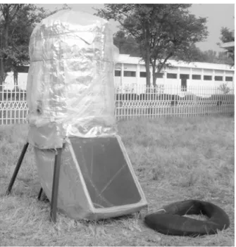
Fig. 2 consists of the plane mirror (aluminum foil) strips pasted on plastic sheet. The size of every mirror strip was 0.1x1m. The sides of the cylinder have the same structure as the reflecting mirror: plane mirror, plastic sheet and plane metallic sheet. Fig. 3 shows fabricated solar biogas digester with flexible gas-holder.
3.
EXPERIMENTAL SETUP
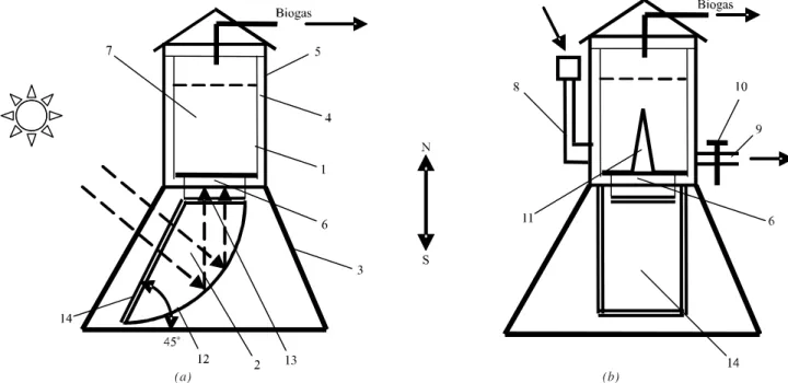
FIG. 1. THE BIOGAS DIGESTER WITH BUILT-IN SOLAR REVERSE ABSORBER HEATER
(1) CYLINDRICAL PLASTIC METHANE TANK (2) A REVERSE ABSORBER HEATER (3) A PYRAMIDAL SUPPORT (4) THERMO INSULATING MATERIAL (5) ALUMINUM FOIL (6) THE METALLIC ABSORBER (7) SLURRY (8) INLET(9) THE OUTLET (10) TAP (11) THE PARTITION (12) THE HORIZONTAL AXES, CYLINDRICAL REFLECTING MIRROR (13) AND HORIZONTAL GLASS COVER
(14) THE INCLINED GLASS COVER
FIG. 2. THE CYLINDRICAL REFLECTING MIRROR OF SOLAR REVERSE ABSORBER HEATER
(1) THE PLANE MIRROR STRIPS (2) THE PLASTIC SHEET (3) THE CYLINDRICAL METALLIC GROUND (4) THE PLANE MIRROR (5) PLASTIC SHEET
(6) PLANE METALLIC SHEET
4.
RESULTS AND DISCUSSION
The optimal temperature range for psicrophilic, mesophilic
and thermophilic bacterias' growth and activity and biogas
production is about 20, 35 and 55oC respectively [5]. In the
winter period usually the average temperature in biogas
digester is lowered that decreases the rate of biogas
production but increases the retention period. For analysis
of the heating of the slurry by solar energy in the biogas
production process the energy balance equation for the
case of a static mass of fluid (the slurry's properties is
considered as water properties) is being heated may be
used [4]:
mc dTf/dt = ατAG - (Tf - Ta )/R (1)
where m is mass of slurry, c is specific heat capacity, Tf is
temperature of the slurry, ? is absorptance of the absorber,
α is transmittance of the glass, A is the exposed area of
the absorber, G is the global irradiance on the inclined
glass cover, Ta is ambient temperature and R is thermal
resistance to heat loss from absorber-slurry system to
the outside environment. The thermal resistance R
reflects all heat losses due to the thermal conductance of
insulating layer of the methane tank, convection and
radiation from the surface of methane tank, evaporation
of the slurry inside of the methane tank (evaporated water
partly condensed after releasing its latent heat and partly
is moved by biogas), and by RAH. As in the RAH
convection and radiation losses inside of it are minimized,
and practically may be neglected. Thus it may be assumed
that mainly heat losses are due to methane tank's thermal
insulator. Taking as a main parameter the maximum
temperature of slurry inside of the methane tank to 50oC
that is close to thermophilic bacterias' growth and
activity, using Equation (1), the thermal resistance can
be determined to be R=0.33 K/W, for the case when α=0.9,
τ=0.81, for two glass layers of A=0.5m2, G=250W/m2, at
the mean annual irradiance, and Ta=20oC and taking into
account the maximum temperature of the slurry dTf/dt=0.
Thermal resistance (R) of the heat conductance given in
[5] is as:
R = ∆x/k Am (2)
where k is thermal conductivity, Am is the area of the side surface and lid of the methane tank, we can determine the thickness of thermo insulating material (∆x). The thickness of thermo insulating material would be equal to 10cm if a thermo insulating material such as glass wool be used. Fig. 4(a-b) shows solar irradiance, slurry's temperature and ambient temperature-time relationships obtained for the one day in October, 2009 (Fig. 4(a)) and March, 2010 (Fig. 4(b)). It is seen that initially Ta>Tf but starting from the noon time, where solar irradiance is the maximum, the slurry's temperature prevails over the ambient temperature.
FIG. 3. FABRICATED SOLAR BIOGAS DIGESTER WITH FLEXIBLE GAS-HOLDER
FIG. 4. SOLAR IRRADIANCE (MW/cm2), AMBIENT TEMPERATURE (oC) AND SLURRY TEMPERATURE (oC) VERSUS TIME FOR ONE
DAY IN OCTOBER, 2009 (FIG. 4(a)) AND MARCH, 2010 (FIG. 4(b))
5.
METHOD OF ENERGY CALCULATIONMETHOD OF ENERGY CALCULATIONMETHOD OF ENERGY CALCULATIONMETHOD OF ENERGY CALCULATIONMETHOD OF ENERGY CALCULATIONThe optimal temperature range for psicrophilic, mesophilic and thermophilic bacterias' growth activity and biogas production is about 20, 35 and 55oC respectively [5]. It is
assumed that due to heating of the slurry by solar energy, the average temperature inside of methane tank is in optimal domain. Daily produced biogas amount, and electric power that may be obtained from this biogas is calculated.
The volume of fluid Vf = 0.7 Vd = 0.56 m3 (V d = 0.8 m
3
is volume of methane tank).
The mass of dry input mo is [5] calculated as:
mc = Vf . ρm = 28 kg (3)
Considering ρm~ 50 kg m-3 [5]
The biogas volume calculated Vb = cmo = 8.4 m3 (4)
c is the biogas yield per unit dry mass (0.2-0.4 m3kg-1)
The energy of biogas E is calculated from [5] is:
E = ηHm fm Vb (5)
Where η is combustion efficiency (`60%), Hm is a heat of combustion (20 MJm-3 at 0.01 atmosphere ), f
m is fraction
of methane in biogas (~0.7). We have obtained E=70.6 MJ.
Assuming retention time tr=20 days, daily produced energy Ede by the biogas digester is calculated as:
Ede = E/tr = 3.5 MJ = 0.97 kWh (6)
If this energy is used daily two hours then the power Peof generator for conversion of biogas energy into electricity will be almost 0.48 kW.
Digester produces daily 0.4m3 of biogas.
Practically it was found that using sewage only and sewage with cow dung the retention times was 4 weeks and two weeks respectively and biogas quantity produced daily was 0.2 and 0.3 m3 respectively during one to two weeks
without feeding by the slurry.
Before the use of the biogas in the generator it is desirable to upgrade it by water scrubbing [6] that increases the
concentration of methane in biogas up-to 88-98%. For this purpose the compressor of 100-200W is needed for pumping of biogas through absorption tower. For the
production of electric power, fueled by the natural gas, generators can be used.
6.
BIOGAS UPGRADING AND
UTILIZATION
To use biogas directly is simple and cheap, but it is acceptable mostly for heating and cooking if concentration
of H2S is sufficiently low. The biogas pressure in this case should be around of 8-25 mbar. To avoid corrosion due to
the presence of H2S, it is recommended to use chimneys made from stainless steel or high temperature resistant plastic. It is recommended to remove water vapor from raw
biogas. In this process H2S is also removed partly. In the case of use of biogas as a vehicle fuel or natural gas in the
present grid the quality of biogas should be improved or upgraded [6]. For this the concentration of methane be increased and carbon dioxide, H2S, water, particles etc. be
removed. Upgraded biogas will have a higher calorific value, constant gas quality, does not have mechanical
particles, and does not bring to corrosion and ice-clogging due to the presence of water. Table 1 shows the requirements to remove gaseous components depending
on the biogas utilization.
CHP (Combined Heat and Power) engine may be an internal combustion engines, a spark ignition engine or a
diesel engine. In the last case it will work as a dual fuel engine. Efficiencies of these engines are 29% (for spark
engine) and 31% (for diesel engine). One of the good applications of biogas is in the gas turbines for electric power generation, but the efficiency of turbines is
sufficiently high at greater powers of around of 800kW. Table 1 show that the up gradation of biogas is important
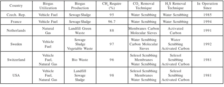
For carbon dioxide removal several methods such as water absorption, polyethylene glycol absorption, carbon molecular sieves and membrane separation were developed. Water scrubbing is the most simple and cheap, and is used to remove CO2 and H2S from biogas because these gases are soluble in water more than CH4. Fig. 5 shows the removal of carbon dioxide and/or hydrogen sulphide from biogas and then its compression. The absorption is a physical process. The absorption tower is one of the important parts of the water scrubbing technology. Biogas under pressure is fed from the bottom of the tower whereas; water under pressure is fed from the top of the tower. The used water is regenerated in desorption tower by de-pressurizing or by stripping with air. The cheap method is to use water without its recirculation and for this for example; water from a sewage treatment plant is available. As it is seen from Fig. 6 that the rectified biogas is used for the generation of electric power that in turn is used to feed compressors, pumps and any other load. Extra gas is compressed and bottled for the use in the vehicles, generators etc.
Polyethylene glycol or Selexol is a trade name and is used for scrubbing; such as for water because it dissolve CO2 and H2S better than the water. In comparison to water, using Selexol the demand for the amount of solvent is less. In the case of Selexol absorption process, recirculation is used.
From coke with micro-range porous, molecular sieve is produced [5]. Molecular sieves separate selectively some
gases from the mixture of gases. The different mesh sizes and/or different applied pressure provide the selectivity properties under absorption process; such as if the pressure is decreases the absorbed gas is desorbed.
TABLE 1. REQUIREMENTS TO REMOVE GASEOUS COMPONENTS DEPENDING ON THE BIOGAS
UTILIZATION
Applicat ion H
2S CO2 H2O
Gas Heater
(Boiler) < 1 ppm No No
Kitchen Stove Yes No No
Stationary
Engine No
(Combined Heat < 1 ppm No Considerat ion
& Power Engine)
Vehicle F uel Yes Recommended Yes
Natural Gas Grid Yes Yes Yes
FIG. 5. REMOVAL OF CARBON DIOXIDE, HYDROGEN SULPHIDE AND WATER FROM BIOGAS AND CONVERSION
OF ITS ENERGY INTO ELECTRIC POWER AND COMPRESSION
(1) TOWER (2) SHOWER FOR WATER SPRAY (3) METALLIC PLATE WITH PORES TO HOLD PACKING (4) PRESSURE
SAFETY VALVE (5) FLANGES (6) VALVE (7) CERAMIC PACKING MATERIAL (DIAMETER=25mm), 8. STAND FIG. 6. SCHEMATIC DIAGRAM OF THE ABSORPTION
Membranes are used for gas separations under high and low pressure systems. In the case of high pressure system; the gas under a pressure of 36bar is cleaned by activated carbon to remove halogenated hydrocarbons, hydrogen sulphide and oil vapor from compressors. After this, gas passes a particle filter and a heater. The acetate-cellulose is used for the fabrication of membranes. The membranes separate small polar molecules as CO2, H2O and H2S, but cannot separate nitrogen from biogas. For low pressure system (pressure is ~1bar); gas-liquid absorption membranes were developed recently: micro porous hydrophobic membrane separates the gaseous phase from the liquid phase. The biogas molecules from the gas phase side flows through the membrane to the liquid side that in turn flow in the direction of membrane's plane and are absorbed. Coral or NaOH are used as absorbent. This system is cost effective and efficient from the point of the removal of CO2 and H2S. As H2S is a very reactive matter, the removal of it is an important task and a number of methods are developed including; air/oxygen or iron chloride addition to biogas or slurry, use of iron sponge, iron oxide pellets, activated carbon, water scrubbing, NaOH scrubbing, biological removal on filter bed, air stripping and recovery. Table 2 shows biogas upgrading and utilization in some European countries and USA. From Table 2, it is seen that water scrubbing is the most popular method for the removal of CO2 and H2S from biogas.
Water removal is realized by: (i) condensation method, (ii) drying method and (iii) absorption of the gas to silica. The
condensation method simply can be realized by using water
taps in the gas pipe. Usually the water removal by this method is sufficient for gas that be used in the engine. In
the drying method the biogas should be cooled. In the result it entrapped in the demister. The absorption dryer
allows achieving high level of water removal from biogas. For these purpose two columns filled by silica is used in
sequence: one column is connected to biogas pipeline system for drying of the biogas, the second column is
regenerated by heating in opened conditions. Fig. 7 shows schematic diagram of the absorption water dryer.
During experimental work that was done in the autumn and spring times the slurry's temperature didn't exceed 40oC. As in summer time the slurry's temperature can be
more than 50oC, therefore a "smart window" is designed
for glass cover of the reflecting mirror based on the Venetian blind regulated by temperature control system, firstly and secondly, thermochromic coating based on
vanadium oxide. These measures allow providing effective temperature dependent controlled shading of the reflecting mirror.
Table 2 shows the main applications of biogas. At the same time biogas energy can be converted into electric
TABLE 2. BIOGAS UPGRADING AND UTILIZATION IN EUROPE AND USA
Country Biogas Biogas CH4 Require CO2 Removal H2S Removal In Operation
Utilization Production (%) Technique Technique Since
Czech. Rep. Vehicle Fuel Sewage Sludge 9 5 Water Scrubbing Water Scrubbing 1985
France Vehicle Fuel Sewage Sludge 96.7 Water Scrubbing Water Scrubbing 1994
Netherlands Natural Landfill Green 8 8 Membranes Carbon Activated 1991
Gas Waste Molecular Sieves Carbon
Vehicle Sewage Water Scrubbing Water
Sweden Sludge 9 7 Carbon Molecular Scrubbing 1992
Fuel
Vegetable Waste Sieves Activated Carbon
Vehicle Selexol Scrubbing Selexol
Switzerland Fuel, Bio Waste 9 6 Membranes Scrubbing 1981
Natural Gas Water Scrubbing Activated Carbon
Vehicle Landfill Selexol Scrubbing Selexol
USA Fuel, Sewage 9 8 Membranes Scrubbing 1981
power and heat by fuel cells. The biogas output may be increased by increasing the number of units of the biogas digesters. This biogas digester may be used domestically as well as for the demonstrative or teaching purposes. In addition based on the results achieved it can be used for the construction of larger volume digesters for use in the farms, especially located in the remote and mountain areas where the climate in the winter period is cold.
7.
CONCLUSION
The biogas digester with built-in solar reverse absorber heater is presented where reverse absorber heater is installed under the methane tank. The temperature of the slurry-solar irradiance and ambient temperature relationships experimentally were investigated. The biogas up gradation scheme for removal of carbon dioxide, hydrogen sulphide and water vapor from biogas and conversion of biogas energy conversion into electric power are discussed.
ACKNOWLEDGEMENT
Authors acknowledge the support of Mr. Saleem, Mr. Rafique, Mr. Maqbool and Mr. Aamir, Under-Graduate Students, Ghulam Ishaque Khan Institute of Science & Technology, Topi, Peshwar, Pakistan, in completing this study.
REFERENCES
[1] Karimov, Kh.S., and Abid, M., "Potentialities of Biogas Technology", VDM Verlag Dr.Muller, [ISBN: 978-3-639-14806-0], Germany, 2009.
[2] Karimov, Kh.S., Dikambaev, Sh. B., Abid, M., Turusbekov, S.K., Bogombaev, E.S., and Vedenev, A.G., "Production and Utilization of Biogas", Avangard, [ISBN 978-9967-432-29-1], Bishkek, 2009.
[3] Alkhamis, T.M., El-Khazali, R., Kablan, M.M., and Alhusein, M.A., "Heating of a Biogas Reactor Using a Solar Energy System with Temperature Control Unit", Solar Energy, Volume 69, No. 3, pp. 239-247, 2000.
[4] Tiwari, G.N., "Solar Energy Fundamentals, Design, Modeling and Applications", Narosa Publishing House, New Delhi, India, 2002.
[5] Karimov, Kh.S., and Abid, M., "Biogas Digester with Buit-in Solar Collector", Proceedings of Global Symposium on Recycling, Waste Treatment and Clean Technology, pp. 1803-1808, Mexico, 2008.
[6] Ilyas, S., "A Case Study to Bottle the Biogas in Cylinders as Source of Power for Rural Industries Development in Pakistan", World Applied Science Journal, Volume 2, No. 1, pp. 127-130, 2006.
[7] Walunj, B.E., and Pawar, S.H., "Role of Catalyst for Improvement of Biogas Quality", Advances in Renewable Energy Technologies, Narosa Publishing House, pp. 234-242, New Delhi, India, 2003.
[8] Parkin, I.P., Binions, R., Piccirillo, C., Blackman, C.S., and Manning, T.D., "Thermochromic Coatings for Intelligent Architectural Glazing", Journal of Nano Research, Volume 2, pp. 1-20, 2008.
[9] Shirage, P.M., Sankpal, S.K., and Pawar, S.H., "Biogas Plants for Fuel Cell Applications", Advances in Renewable Energy Technologies, Narosa Publishing House, pp. 269-293, New Delhi, India, 2003.