Modeling and Testing of a PV/T hybrid system with Water based
Optical Filter
Sachin Gupta and Usha Bajpai
Centre of Excellence in Renewable Energy Education and Research, University of Lucknow (New Campus), Lucknow- 226021, India
Abstract
A theoretical model has been developed for the Non-imaging V-trough hybrid PV/T concentrator systems along with optical filter and validated with the designed and fabricated system to assess over all thermal efficiency of the PV/T system. A V-trough concentrator system has been developed for two axes tracking. Commercially available solar modules were evaluated for their usability under 2-sun concentration. V-trough concentrator with geometric concentration ratio of 2 (2-sun), we are getting an average overall efficiency of the PV/T system increased by 23.54 % extra overall thermal efficiency of the PV/T system as compared to the solar module efficiency at standard test conditions.
Key words
– PV/T Systems, Hybridization, Optical Filter, Overall thermal efficiency, V-troughI.
Introduction
Energy play an importance role in the development of the country, so the Government of India had launched a Solar Mission to enhance the utilization of solar energy for power generation, to achieve therapid development of the nation and to enhance the living standard of the people.
India belongs to the tropical region, so the solar energy is widely available here. Solar PV/T system are very good for per meter square area utilizability of solar energy. A hybrid solar energy conversion system is the combination of solar PV and the thermal system (PV/T) which increases the overall efficiency of the solar energy.
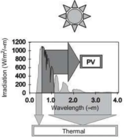
PV spectrum response is highly dependent of band-gap of solar cell and is most efficient when wavelength of light is near to the band-gap energy. The remaining part of the solar spectrum can be utilized for the thermal system.
Solar energy spectrum covers vast range of electromagnetic waves from 280 nm to 4000 nm wavelength. It has 4.62% UV, 53.85% VIS and 41.53% IR. A typical solar cell uses some part of UV and all part of visible and some part of IR. The crystalline solar cell quantum efficiency lies is in between 300 nm to 1190 nm wavelength of solar radiation, the rest of the energy is converted in to heat which increase the temperature of the solar cell. The rise in the temperature of the solar cell reduces the solar cell efficiency by -0.0045 % per 0C [1].
During the time period from 1978 to 1981, the development of combined photovoltaic/thermal
(PV/T) collectors was pursued. Collector
development began with the testing of commercially produced air and liquid PV/T prototype units and culminated in a second generation of collector units.
Both air-and liquid-type collectors were developed as part of the second-generation effort. [9]
Many novel concepts have been tested to remove the excess heat in PV/T system most common are air and water put directly contact with the PV/T system with different flow pattern to remove excess heat. The heat can be withdrawn from the back side of the solar PV panel. In this type design, the working fluid is directly in contact with PV system and thereby removes excess heat. But, this type of design has drawback that the decrease in efficiency of solar cell due to value of higher output temperature from the thermal system. In concentrating solar PV/T systems, the radiation on the concentrating solar PV/T systems and the radiation on the receiver is high causing the compromise in performance to be even more pronounced [2] and an optical filter/beam splitter can be used to remove the heat from the PV/T system and also has solution to the challenges discussed above.
The concept of spectral selectivity in the design of combined photo-quantum/photo-thermal solar convertors can be the basis for improving the overall conversion efficiency of hybrid solar energy systems. Spectral selectivity allows those photons not easily utilized by the photovoltaic (PV) system to be separated and channeled into a thermally decoupled loop [3].
Studies have shown that pure fluids such as water and organic fluids can be used in PV/T systems as a beam splitters. [7]. Dichroic filter and nano-fluids can also be used to filter out the solar radiation for PV/T system [10],[2].
In this work, we have used water as an optical filter because it has very good absorption in the IR range and very cheap material available. An optical filter is required which can filter out the unnecessary
solar radiation and prevent from heating of the solar cell. From the study we have found that water can be used with low concentration PV/T system. A study for the thickness of water as an optical filter had been carried out. The optimal thickness of the water based optical filter is about 2 cm [4]. The working of water based optical filter is shown in Fig 1. The splitting of the solar spectrum into components for PV and thermal energy conversion is depicted in Fig 2.
Figure 1. Working of Optical Filter
Fig2. Splitting of the solar spectrum into components for PV and thermal energy conversion [8]
II.
Design concept
Concentrating PV/T system can be made by standard photovoltaic panel and integrate it with optical filter and V-trough a shown in Fig 3.Optical filter has been placed above the solar panel. Here optical filter work as thermal collector and V-trough is used to increase the input solar energy. For the concentration of the solar radiation V-trough has been used because it is non-imaging collector and it concentrate the solar radiation more uniformly. A 3 mm glass sheet has been used for optical filter and normal Reverse Osmosis (RO) water has been used for the optical filter.
The opaque PV-panel is the standard shell solar polycrystalline PV-panel consisting of glass/EVA/ ARC/Si/EVA/PE-Al-tedlar.
In this study a model was developed to calculate the performance of the optical filter based PV/T system which uses a flow channel as shown in Fig1. The solar radiation reaches the solar cell through optical filter which absorb the unnecessary solar radiation. The thickness of the water is optimized according to quantum efficiency of the solar cell. Water absorbed the energy from the solar radiation hence the rise in temperature which was observed by the time it came out. In between optical filter and PV cell air is present to avoid the heat transfer from optical filter and PV. A standard PV has been used to generate electricity.
2.1 V-trough design
There are various imaging and non-imaging concentrating collectors for concentrating the sun rays. For solar cell, it require seven illumination on the solar cells and so, we have chosen non-imaging trough collector. There are several designs of V-trough, which can be categorized according to their tracking mode, Seasonal tracking, one axis north-south tracking and diurnal tracking. Here we have designed and developed V-trough with concentration ratio as 2.Trough reflector has been made of high reflective mirrors. V-trough parameters are as follows:
Concentration ratio - 2
Trough angle - 30 degree
Reflector height - 27 cm
Fig 3. Non-imaging V-trough hybrid PV/T system with optical filter
2.2 Solar Module
Poly-crystalline solar module has been
manufactured by the Central Electronics Limited, India, whose standard test conditions (STC) specifications are as follows-
Voc = 9.31 V
Isc = 0.76 A
Pmax = 4.77 W
Vpm = 7.03 V
Ipm = 0.66 A
FF = 0.66
TheI-V characteristics of the solar module given by the manufacturer are shown in Fig 5.
Figure 5. I-V characteristics of the solar module
2.3 Optical Filter
The spectral energy control is a major factor in attaining high efficiency for this hybrid PV/T energy converter. Placing of an optical filter between the parabolic concentrator and photovoltaic array is one method for spectral control and has been used in this current model.
In order to achieve high system efficiency, the filter must have low absorptance. It must have large transmittance in the useful photon energy region (≥Eg, energy band gap) of photovoltaic solar cell and
good absorption in the other energy region.
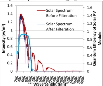
Fig 4.Comparison of Solar Radiation with Quantum Efficiency of Solar PV Module before Filtration and
after Filtration at 2 cm Water Depth
The silicon solar cell has band gap of 1.12 eV. So, ideally below the band gap (above the 1100 nm wavelength), the photons have not enough power to move electrons from valance band to conduction band. Si is an indirect band gap semiconductor, so,
there is no sharp cut-off at the 1100 nm wavelength as shown in Fig4.In this case, 2 cm thickness of water has been taken as explained above.
It is clear from theoretical calculation that about 30% of energy is absorbed by optical filter which is mainly above 1100 nm wavelength as has been shown in Fig 03. After filtration of the radiation, about 99.00% of energy of the filtered radiations falls in the range of 300 nm to 1190 nm. From the Table 01, it is clear that 31.45 % of energy absorbed by the optical filter and rest of energy is transmitted towards solar module.
Table 01: Energy absorbed by the optical filter inclusive of upper and lower glass effect
Total energy: 887.64 W/m2 Depth
of water (cm)
Energy available for solar module
Total energy availabl
e for
solar module
Energy absorbed by optical filter (%) Ener
gy in betw een 280n m-300n m
Energy in betwee n 300nm -1190n m
Energy in betwee n 1190n m-4000n m
1.5 0 613.05 8.67 621.75 29.96
1.75 0 607.90 6.75 614.67 30.75
2.00 0 603.17 5.26 608.43 31.45
2.25 0 598.74 4.11 602.85 32.08
2.3 Material selection
For the system design we have used materials that are generally applied in conventional PV laminates. In the thermal collector the normal silica glass is used, for valid comparison of concept and practical model.
A standard poly crystalline PV panel consists of glass/EVA/ARC/Si/EVA/PE-Al-tedlar layers, which has been used for the study which was manufacture by the Central Electronics Ltd. India.
III.
Theoretical model
A theoretical model has been developed in this study to calculate the performance of the PV/T system design. Solar radiation inters in the optical filter which absorb the solar radiation which is not useful for the solar photovoltaic panel and allow rest of energy to reach the solar cell. This optical filter are matched with the quantum efficiency of the solar cell as shown in Fig 4. Water has a property to absorb radiation in the range of IR and some part of UV. The characteristic of optical filter has been discussed above and the thermal and electrical efficiency has been discussed here.
0 0.2 0.4 0.6 0.8 1 1.2 1.4 1.6
0 0.2 0.4 0.6 0.8 1 1.2 1.4 1.6
Qu
an
tu
m
E
ff
ic
ie
n
cy
o
f Sol
ar
PV
M
o
d
u
le
In
te
n
ci
ty
(w
/m
2)
Wave Lenght (nm)
Solar Spectrum Before Filteration
The incoming solar radiation is assumed to be at an air mass of 1.5. The solar spectrum values were taken from (ASTM G173-03, 2014, “Standard Tables for Reference Solar Spectral Irradiances,” 2014) and transmission of the glass were considered for the calculation the filtered solar radiation in Sachin et al, 2014. Fig 04 shows the comparison with the filtered solar radiation.
The thermal model is steady-state based on the solving the heat balance equation for all the layers in the PV/T collector. First we characterized the optical filter, temperature analysis of PV and water channel and then finally thermal and electrical efficiency of the PV/T system.
The result of the measurements and the calculation are the useful energy produced by it and the efficiency of the PV/T system. Efficiency is defined by the output of the collector is divided by the amount of energy received by the collector. So the thermal and electrical efficiencies are-
ηℎ= ( − 𝑖 )
𝐴 𝐺 (1)
η𝑒 = 𝑉𝐼
A 𝐺 (2)
Electrical efficiency is temperature dependence of the PV, so the Eq. (2) is used for the electrical efficiency of the PV.
η =η0 1−0.0045 𝑒 −25 (3)
The overall thermal efficiency(η)of the hybrid solar PV/T system can be written as:
η=ηℎ+ η𝑒
0.38 (4)
Overall thermal efficiency of the PV/T system is equal to the sum of thermal efficiency of the PV/T system and the ratio of electrical efficiency to c power, [6], where c power is the electric power generation efficiency of a conventional power plant. For the calculation of the various temperatures of the PV/T system such as glass temperatures of the channel and solar module, solar cell temperature and water output temperature etc. heat balance equation were applied at various point of the system as shown in Fig5 and eight polynomial equation of order four has been developed for eight variables.
IV.
Numerical modeling
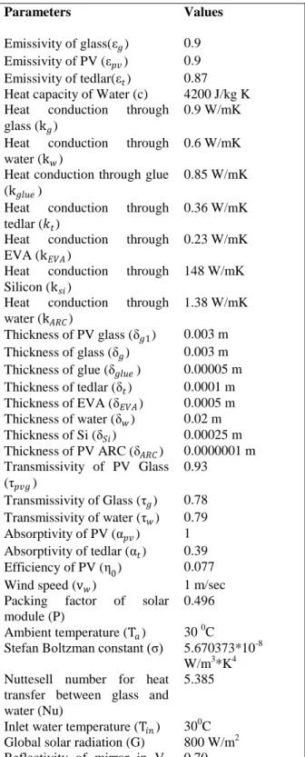
Whenη0 = 0.077 for the given PV, Table 2 are shows the values of parameter that are used in the model for calculation.
Table 02: Design parameter of the PV/T solar collector
Parameters Values
Emissivity of glass( 𝑔) 0.9
Emissivity of PV ( ) 0.9
Emissivity of tedlar( ) 0.87
Heat capacity of Water (c) 4200 J/kg K
Heat conduction through
glass (k𝑔)
0.9 W/mK
Heat conduction through
water (k )
0.6 W/mK
Heat conduction through glue (k𝑔 𝑒)
0.85 W/mK
Heat conduction through
tedlar ( )
0.36 W/mK
Heat conduction through
EVA (k𝐸𝑉𝐴)
0.23 W/mK
Heat conduction through
Silicon (k𝑖)
148 W/mK
Heat conduction through
water (k𝐴 𝐶)
1.38 W/mK
Thickness of PV glass ( 𝑔1) 0.003 m
Thickness of glass ( 𝑔) 0.003 m
Thickness of glue ( 𝑔 𝑒) 0.00005 m
Thickness of tedlar ( ) 0.0001 m
Thickness of EVA ( 𝐸𝑉𝐴) 0.0005 m
Thickness of water ( ) 0.02 m
Thickness of Si ( 𝑖) 0.00025 m
Thickness of PV ARC ( 𝐴 𝐶) 0.0000001 m Transmissivity of PV Glass
( 𝑔)
0.93
Transmissivity of Glass ( 𝑔) 0.78 Transmissivity of water ( ) 0.79
Absorptivity of PV (α ) 1
Absorptivity of tedlar (α) 0.39
Efficiency of PV (η0) 0.077
Wind speed (v ) 1 m/sec
Packing factor of solar module (P)
0.496
Ambient temperature (T ) 30 0C Stefan Boltzman constant ( ) 5.670373*10-8
W/m3*K4 Nuttesell number for heat
transfer between glass and water (Nu)
5.385
Inlet water temperature (T𝑖 ) 300C
Global solar radiation (G) 800 W/m2
Reflectivity of mirror in V-trough (R)
0.70
show the heat balance for the optical filter with water as shown in Figure 5. Equation (5) represent the heat flow fromtedlar sheet to atmosphere.Left hand sideof the equations show the energy converted to the heat and the right hand side of the equations show the losses. Equation (6) shows the heat balance for the solar cell. Equation (7) shows the heat balance for the glass 1 above solar cell. Equation (8) and (9) show the heat balance for the lower and upper glass 2. Equation (10) show the heat balance for the water channel. Equation (11) and (12) show the heat balance for the lower and upper glass 3.
Figure5. Heat balance flow diagram of PV/T system
𝑔3 𝑔2 𝑔1α𝐺 A 1− 𝑃 +𝑃 q
= q ,− −q ,− (5)
𝑔3 𝑔2 𝑔1𝐺 A α 1−η
= q , + q ,𝑔1 (6)
𝑔3 𝑔2 𝐺 A 1− 𝑔1 +𝑃 q ,𝑔1
= q ,𝑔1−𝑔2− q ,𝑔1− (7)
q ,𝑖 𝑔2− + q,𝑔2−𝑔3= q𝑔2 (8)
𝑔3 𝐺 A 1− 𝑔2 = q ,𝑔1−𝑔2−q𝑔2 (9)
q ,𝑖 ,𝑔2− + 𝑔3𝐺 A 1− + q ,𝑔2−𝑔3 1−
= q , , −𝑔3−ṁ (T −T𝑖 ) (10)
q , , −𝑔3+ q ,𝑔2−𝑔3+𝐺 A 1− 𝑔3
= q𝑔3 (11)
q𝑔3= q , + q , (12)
Equation from (5) to (12) for heat flow contain 8 unknown temperature (T𝑒 ,T, T𝑔1, T𝑔2 , T𝑔2 , T , T𝑔3 , T𝑔3 ). Equations have been solved by the
Newton-Raphson iterative method by the help of MATLAB. The heat transportation equations are given in Appendix-A.
V.
Results
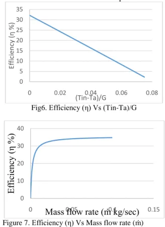
Figure 6–7show the plots of thermal efficiency of the proposed model as a function of (Tin-Ta)/G and ṁ respectively. The results show that as (Tin-Ta)/G increases, thermal efficiency of the PV/T
system decreases as shown in Figure 6. Maximum efficiency is about 32 %. Similarly, as the ṁ increase, the thermal efficiency of the PV/T system also increases.Figure7 shows the fall in the efficiency of solar cell with rise in the solar cell temperature.
Fig6. Efficiency (η) Vs (Tin-Ta)/G
Figure 7. Efficiency (η) Vs Mass flow rate (ṁ)
The experiments were conducted to measure the performance of the PV/T system with water based optical filter. All the experiments were conducted in between 10 am to 3 pm. For the concentration of solar radiation, V-trough has been used with concentration ratio of 2. V-trough has been tracked with the sun in the interval of 10 minutes. The solar module has been placed behind the optical filter. With the solar module, three battery of 6 volt each has been connected and in the interval of 10 minutes, the values of voltages and currents were recorded with multi-meter, solar radiation on tilted surface was recorded and temperature of the solar module and water has also been recorded.
The thermal performance of the PV/T system is evaluated and thermal efficiency of the system is analyzed according to the methodology given above and the curve between (Tin-Ta)/G and efficiency has been plotted as shown in Figure8. Thegiven curves show that as the temperature of the collector increases, the thermal efficiency has decreases and ultimately becomes zero.
It has been calculated about 31% of energy is absorbed by the optical filter and the rest of energy reaches to the solar module. Experimentally, we get
0 5 10 15 20 25 30 35
0 0.02 0.04 0.06 0.08
Ef
fici
en
cy
η
%
(Tin-Ta)/G
0 10 20 30 40
0 0.05 0.1 0.15
Ef
fic
ie
nc
y
(η
%
)
the maximum thermal efficiency of the thermal optical collector as 30% with small variations.
Fig8. Curve between (Tin-Ta)/G and thermal
efficiency (ηth) of the thermal optical collector
Fig9.Curve between temperature of the PV module (Tcell) and electrical efficiency (ηel) of the PV module
Figure 10. Curve between efficiency (η) and ambient temperature (Ta)
The efficiency of the solar module decreases slowly as compared to thermal efficiency of the PV/T system. Average efficiency of the system is much more as compared to the single solar module as calculated in Table 02. The overall efficiency of the PV/T system is much higher than single solar module standard efficiency. We are getting an average 23.54 % extra efficiency of the PV/T system as compared to the STC solar PV module efficiency.
VI.
Conclusion
Using of water, which is not a costly material in PV/T systems with concentration as an option for optical filter, is a good proposition as demonstrated in this work. The experimental setup for such a system has been fabricated using the depth of water as 2.00 cm. The experimental results are to be reported in this work.
Photovoltaic thermal system (PV/T) is better than unique solar module because the waste energy can be used and the solar module can be cooled to increase the electrical efficiency. In the study, the PV/T system can be installed consisting of solar module, optical filter and a V-trough. In the normal distribution of daily solar radiation condition, water temperature in the optical filter can be heated up to 63℃. The thermal optical filter has good optical efficiency of about 30% and the solar module electrical efficiency has 7~5.5%. However, there is about 23% extra efficiency of the PV/T system as compared to the STC solar PV module efficiency.
Nomenclature
Ac= Aperture area (m2)P = Packing factor
q = Heat flux (W/m2) cp= Specific heat (J/kgK)
G = Global solar radiation (W/m2) T = Temperature (K)
R = Reflection η = Efficiency (%)
h = Heat transfer coefficient (W/m2 K) V = Voltage
I = Current
vw = Wind velocity(m/sec)
= Stefan-Boltzman constant =Emissivity
= Transmittance Nu = Nusselt number
k = Thermal conductivity (W/mK) l = Thickness (m)
α = Absorptivity
Subscripts
g1 = Glass 1 g2 = Glass 2 g3 = Glass 3 w = Water t = Tedlar
r = Radiative heat transfer c = Convective heat transfer a = Ambient
in = Input out = Output Si = Silicon EVA = EVA glue
channel = Water channel in optical filter ARC = Anti-reflective coating
0 10 20 30 40 50 60
0 0.01 0.02
ηth
(%
)
(Tin-Ta)/G
4 4.5 5 5.5 6 6.5 7 7.5 8 8.5
40 45 50 55
ηel
(%
)
Tcell(0C)
0 50 100
36 37 38 39 40 41
η
(%
)
Ta(0C)
Thermal efficiency
PV efficiency
pv = Photovoltaic panel
Appendix A: Heat transportation equations
q = h (T𝑒 − T )
q ,− = h (T − T )
q ,− = ( 4− 4)
q ,𝑔1= h𝑔1 (T𝑒 − T𝑔1)
q𝑔2=
k𝑔2 (T𝑔2 −T𝑔2 ) l𝑔2
q𝑔3= k𝑔3 (T𝑔3 − T𝑔3 )
l𝑔3
q ,𝑔1−𝑔2=
(𝑔41− 𝑔42 ) 1
𝑔1+
1
𝑔2−1
q ,𝑔1− = h (T𝑔1− T )
q ,𝑖 ,𝑔2− = hℎ 𝑒 (T𝑔2 − T )
q ,𝑔2−𝑔3= (𝑔2
4 −
𝑔43 )
1
𝑔2+
1
𝑔3−1
q , , −𝑔3= hℎ 𝑒 (T − T𝑔3 )
q , = 𝑔3 ( 𝑔43 − 4)
q , = h (T𝑔3 − T )
h = 𝑖 2
𝑖 + +
𝐸𝑉𝐴 𝐸𝑉𝐴
−1
ℎ = 5.7 + 3.8
ℎ ℎ 𝑒 = 𝑁
h = 𝑖 2
𝑖 +
𝑔1
𝑔1+
𝐸𝑉𝐴
𝐸𝑉𝐴 +
𝐴 𝐶 𝐴 𝐶
−1
ℎ =
Acknowledgment
The authors are thankful to the Ministry of New and Renewable Energy, Government of India, New Delhi for granting Senior Research Fellowship to one of the author under the National Renewable Energy Fellowship Programme.
References
[1] F Sarhaddi, S Farahat, H Ajam and A Behzadmeh, (2011), Exergetic optimization of solar photovoltaic thermal (PV/T) air collector, International Journal of Energy Research, Vol.35, pp. 813–827.
[2] Robert A Taylor, Todd Otanicar and Gary
Rosengarten (2012), Nanofluid-based
optical filter optimization for PV/T systems, Light: Science and Applications, Vol. 1, e34.
[3] M A C Chendo, M. R. Jacobson and D. E. Osborn, (1986),Liquid and thin-film filters for hybrid solar energy conversion systems, Solar and wind Technology, Vol.4, No.2, pp. 131-138.
[4] Sachin Gupta and Usha Bajpai, (Oct 2014), Optimization of water based optical filter for
concentrated crystalline Si PV/T system - A theoretical approach, International Journal of Current Engineering and Technology, Vol.4, No.5, pp. 3151-3156.
[5] CS Sangani and C S Solanki, (2007), Experimental evaluation of V-trough (2
suns) PV concentrator system using
commercial PV modules, Solar Energy Materials & Solar Cells Vol. 91, pp. 453– 459
[6] BJ Huang, T H Lin, W C Hung, and FSSun,
(2001), Performance evaluation of solar photovoltaic/thermal systems. Solar Energy, Vol. 70 (5), pp. 443–448.
[7] J Kaluza, K H Funken, U Groer, A
Neumann, K J Riffelmann, (1999),
“Properties of an optical fluid filter: Theoretical evaluations and measurement results.” J Phys IV, 9: Pr3-655-Pr3660.
[8] A G Imenes and D R Mills, (2004),
“Spectral beam splitting technology for increased conversion efficiency in solar concentrating systems: a review,”Solar Energy Materials and Solar Cells, vol. 84, no. 1–4, pp. 19–69.
[9] S D Hendrie, (1979), “Evaluation of combined photovoltaic/thermal collectors.” In: Proceedings of the international conference ISES, vol. 3,Atlanta, Georgia, USA, May 28–June 1, p. 1865–69.