Sequence in the Assembly of a Rigid Circular Structure
MUJEEBUDDIN MEMON* TANVEER HUSSAIN**, AND ZEESHAN ALI MEMON***
RECEIVED ON 27.04.2012 ACCEPTED ON 18.09.2012
ABSTRACT
In order to increase the performance and to produce environment friendly aero engine, it is necessary to
reduce the weight of the engine. A significant proportion of an engine's weight is due to the large
castings used to form the main non-rotating structures. Replacement of these large castings with
circular structures fabricated by assembling uniformly segmented circular components could provide a
significant weight reduction. Due to various advantages of fabricated rigid structure of an aero engine
casing, this article proposes that components should be assembled while considering optimum mating
sequence to minimize assembly error and to reduce assembly time and cost. The algorithm based on
connective assembly model is proposed to predict stage-by-stage assembly variations. A computer program
is also developed to perform automated tolerance analysis and to find optimum mating sequence of
component. The assembly variations are minimized based on three criteria of selection of assembly
mating sequence. The results have shown that the three criteria may be used every time for tolerance
analysis and to minimize variation propagations in the assembly of rigid circular structures.
Key Words: Assembly Modeling, Regid Circular Structrue, Assembly Variations, Varation
Propagation, Assembly Optimization.
*Professor, **Lecturer, and **Assistant Professor,
Department of Mechanical Engineering, Mehran University of Engineering & Technology, Jamshoro.
1.
INTRODUCTION
engines such structures were fabricated by welding the sheet metals [2]. Due to high cost associated with the complex fixtures used and time involved in repetition of assembly process in order to reduce error accumulation in the final assembly, the fabrication method was abandoned. On other hand, there are two main advantages of using fabricated structures consisting of small castings and sheet components, it tends to have better structural properties compared to cast and so thinner sections can be used and no extra material is required to support the casting processing.
Circular-build assembly optimization method is proposed in this paper to minimize error accumulation in the assembly of fabricated components. Circular-build assembly method is way of joining parts together in order to maintain symmetric distance between all parts and the axis around which the components are assembled. If the components are assembled symmetrically around an axis with no error, they form a perfect circular structure. In such assemblies, the components are assembled carefully such that they are positioned symmetric about an axis. In circular-build structures, the component parts are ideally identical in shape and dimensions. The assembly of identical component parts have freedom of selecting an assembly sequence of the mating component that gives minimum assembly variation. The total number of possible mating sequences depends on the number of total assembly components. Higher the number of components in the assembly higher the number of assembly sequence combinations. A study of predicting variation propagation in the circular-build assembly is presented in this paper. Instead of analyzing real example of aero engine structure, this paper uses the example of an assembly very similar to circular-build structure used in aero engines. Fig. 1(a) shows an assembly of ten components with identical nominal dimension, in which the component parts are put together to build circular structure. Each component part has a uniformly segmented circular shape as shown in Fig. 1(b). Assembling such components by selecting optimum assembly sequence is an effective approach to reduce assembly time and cost and to minimize the overall variation in the assembly.
A machine can produce parts within definite limits of dimensional accuracy. Variations in the produced part reflect the inherent inaccuracies within the machine structure itself [3]. Due to inevitable variations in any production process, the quality of the assembled product is dependent on variation of the component parts [4]. The components which are supposed to be produced identical in shape contain variations from
each other. The variations accumulate as parts are assembled together [5]. These variations if increased can quickly drive assembly dimensions out of specification [6]. In mechanical assembly, the parts share their mating features with each other. For complex assemblies it is necessary to investigate the impact of geometric variation of part on assembly variation [7].
FIG. 1(b). UNIFORMLY-SEGMENTED CIRCULAR COMPONENT
Therefore, this paper considers only the effect of both dimensional and geometric variation of component in the quality of final product. This issue does not consider the role of assembly process variation and measurement error in the assembly modelling, whereas, t h e e f f e c t o f a s s e m b l y p r o c e s s v a r i a t i o n a n d measurement error on final product is the objective of next issue.
In circular-build assembly structures, the clearance between the mating parts at final assembly stage should be within a given specification range. A product is rejected when its clearance is outside this range. Assembling the mating components in a random fashion may lead to a large number of rejected products. In these situations, selection of optimum assembly sequence should be an effective method in reducing the rejection rate. By changing the mating sequence of assembly component in circular-build assembly structure, the parts can be assembled successfully in order to achieve the desired final assembly configuration.
This paper thus analyses the effect of component variation on final assembly quality at all possible combinations of components' mating sequence. The mating sequence that gives optimum results is selected for consideration in practical assembly.
2.
AIMS AND OBJECTIVES
The current study is aimed to analyse and control variation propagation in the assembly of circular-build structures by identifying optimum assembly sequence of the mating components. The measureable objectives are to develop a computer program that generates possible combinations of mating sequence of the components, calculate assembly variation propagation using connective assembly model and to investigate what parameters need to be selected to help in decision making for choosing best mating sequence of components. The item wise objectives of this study are:
To determine possible combinations of mating sequence of assembly components.
To predict the variation propagation in the assembly at each mating sequence of the assembly component.
To evaluate the mating sequence of components that gives optimum assembly results.
To determine the effectiveness of changing the mating sequence of assembly component in the assembly quality.
3.
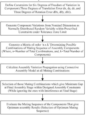
METHODOLOGY
The methodology developed in order to predict and control variation propagation in the assembly of circular-build structures is illustrated in Fig. 2. In order to achieve the research objectives, this section presents an overview of methodology for circular-build assembly structure. Fig. 2 shows the step by step methodology for predicting and controlling variation propagation in circular-build structures at conceptual stage of design. At the conceptual stage of design, actual component variation obtained from measurement data of each component is not known. Thus, in this study, the variations at each mating feature of the component are randomly and normally generated in Matlab. The values for components variation are generated within specified tolerance zone limits.
4.
COMPONENT VARIATION
CONSIDERATION/TOLERANCE
REPRESENTATION
Manufacturing fluctuations result in dimensional variation of the parts of an assembly. The variation in manufacturing can also cause geometric form and feature variation. The form variations such as flatness variation cause additional assembly variation in the placement and orientation of a component [8]. Thus, both dimensional and geometric variations propagate and accumulate throughout an assembly. Geometric variations contribute significantly in the performance of an assembly and should be considered in assembly variation analysis [9].
In order to conduct automated assembly variation analysis,
an appropriate tolerance representation scheme has to be established. Tolerance representation schemes are used
to represent a part with tolerance surface/feature. In a tolerance representation scheme, variations are assigned to a set of model design variables. Variations of those model variables are so constrained that the imperfect feature of the real part always lies in a region of specified tolerance zone [10]. Once the tolerance zone is established, a new surface is needed to represent the variant boundary surface.
In a tolerance representation scheme, geometric variations of the component can be described by defining relative situation between the nominal feature
and the actual feature of that component [11]. To describe relative situation between actual and the nominal mating feature, it is assumed in this study that a Cartesian frame is attached at the centre of both
nominal as well as actual mating feature. The variations of actual frame of reference are defined in terms of location and orientation error with reference to the
nominal frame of reference attached to the corresponding nominal mating feature.
In real world, for high value low volume products like jet
engines, each component part of circular-build structure is measured before the assembly. Thus the actual mating features of the component parts can be defined by a plane
that best fit the measurement data. The variations of the plane representing the actual mating surface are thus defined by the coordinate frame attached to best fit plane.
These variations are defined in terms of translation (dx,dy,dz) and rotation (dθx, dθy, dθz) of the attached coordinate frame from nominal.
The current study does not include real measurement of the component variation, thus the real surface variations in terms of translation (dx,dy,dz) and rotation (dθx,dθy, dθz) are randomly generated as normally distributed
design variables within the prescribed variational constraints.
5.
VARIATION PROPAGATION
MODEL
Connective assembly model is used here to calculate variation propagation in the assembly. A connective assembly model is the type of assembly model in which the parts are joined by connecting them at their assembly features. A connective assembly model can represent parts, assembly features, and surfaces individually and can tell the difference between them. This makes it possible to model different kinds of variation correctly and to distinguish in the model different sources of error. In assembly modelling, it is assumed that reference frames are attached to each matting feature of part by means of a matrix transform relative to the part's origin coordinate system. In the Connective assembly model, accumulated assembly variations are described by the position and orientation of the coordinate frame attached to mating feature of the assembled component. The model also assumes that parts are assembled by joining mating features to each other [12]. The transform matrix can represent the operation of rotation and translation on a coordinate frame originally aligned with reference coordinate frame [13].
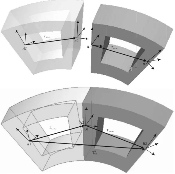
Assembly of two parts then consists of putting the features' frames together, and composing transforms to express the part-to-part relationships. These relationships are illustrated in Fig. 3.
A1 and A2 are the centres at the two mating features of the component A, whereas, B1 and B2 are the centres on the two mating features of part B. The proposed assembly model is described as follows. If no errors are present then the relationship between feature A1 and A2 on Parts A can be expressed as:
2 1 1 2 2
1 A TA B TB B
A T N AB
T = − × − × − (1)
Where TN
AB, TA1-A2, TA2-B1 and TB1-B2 are transforms to express
the relationships between two parts and their mating features after mating. TN
AB is the nominal transform from
A1 to B2, TA1-A2 is the transformation from part A's frame A1 to frame A2, TA2-B1 is the interface transform from feature frame A2 on part A to the feature frame B1 on part B, and
TB1-B2 is the transform from the feature frame B1 on part B
to its coordinate frame B2.
The transforms TN
AB can be expressed as:
⎥
⎦
⎤
⎢
⎣
⎡
= 1 0t N AB p N AB R N AB T (2)Where RN
AB is a 3x3 rotational matrix indicating the
orientation of the new frame relative to the old one, pN AB is
a 3x1 displacement vector indicating the position of the
new frame relative to the old one, and superscript 't'
indicates a vector or matrix transpose.
If a feature on a part is not placed in its nominal design
position, there is an error of position and
mis-orientation for the feature. For example, if part A has a variation, the feature on part A is mis-positioned and
mis-oriented to feature TA1-A2’ this variation is described
by DA, and the transform relating it to part A's origin is
then:
A
D
A
A
T
A
A
T
−
=
−
×
2
1
'
2
1
(3)Therefore, the assembly of two components A and B can be expressed as follows:
B D B B T B A T A D A A T AB
T' = 1− 2 × 2− 1× 1− 2 (4)
In Equation (4), T’
AB can be rewritten as:
(5)
Comparing Equation (1) and Equations (4), the translational error vectors can be calculated, for the assembly of the two components A and B, with considering parts variation, process error and measurement noise.
Thus, the translational error vector as is:
(6)
Where pAB and pN
AB are translational vectors for the
associated assemblies. Similarly, the translational error vectors can be calculated at any assembly stage for any other cases described above.
6.
C
C
C
C
C
OMPUTER MODEL FOR
VARIATION PROPAGATION AND
CONTROL
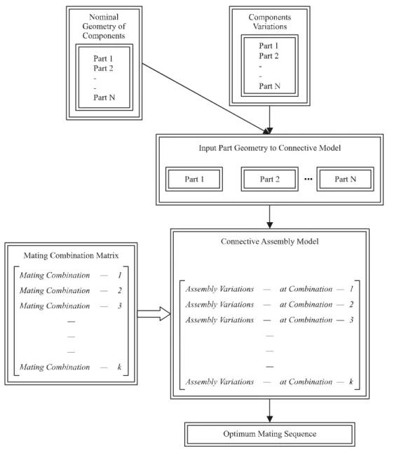
A computer program is developed in Matlab to calculate variation propagations and to find optimum mating sequence of the components that gives minimum error in the assembly of circular-build structure. Fig. 4 shows the process diagram of computer model generated in
the Matlab. The computer model developed in Matlab is very robust and is also capable to perform variation propagation analysis based on measurement data of real component. For the current study, instead of using real measurement data, model design variables are randomly generated as normally distributed numbers based on the '±3σ principle' for the given tolerance zone limits. In a normal/Gaussian distribution, 99.73% of the data points lie within ±3σ from the mean [14-15].
Once the component variations are generated, these variations along with nominal dimension of the
components are given as input to connective assembly model to predict assembly variation propagations for all
possible mating combinations. The model further analyse
the variation propagations at all combinations and select the one that gives minimum assembly errors.
7.
CASE STUDY
There are 10 uniformly segmented circular components
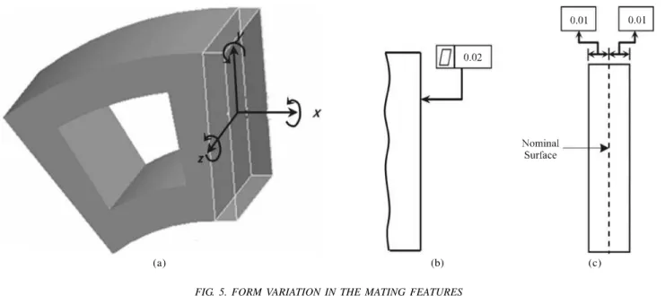
which are assembled together to form a circular-build structure (as shown in Fig. 1). Each uniformly-segmented
circular component has inside diameter of Di(626mm), outside diameter of Do(1292mm) with tolerance of ±0.01
mm in each diameter, and the thickness of t(200 mm) with
allowable variation of ±0.01 mm in thickness. The allowable surface variation at mating features of the component is
tf=0.02mm (as shown in Fig. 5). For assembly modelling, the form tolerance for surface roughness is defined in
terms of minimum material condition of 0.01mm, and
maximum material condition 0.01mm from nominal surface (as shown in Fig. 5(c)). Mathematically it is described in
similar way to size tolerance as ts= ±0.01mm.
The two mating surfaces are flat.
Frames F is attached to the centre of nominal feature, and F' is attached to the feature with variation.
The centre of the axi symmetric assembly structure is the origin (0,0,0) in the global coordinate system.
Frame F' related to Frame F, has a translation error of (dx,dy,dz) and an angular error of (dθx, dθy, dθz).
Size variation only contribute in translation errors (dxs,dys,dzs), whereas, form variation contribute in both translation (dxf, dyf, dzf) as well as rotation errors (dθxf, dθyf, dθzf).
In each uniformly-segmented circular components, the size tolerance is constrained within the prescribed value of tolerance, whereas, form tolerance contribute in terms of translation as well as rotation error. Thus following constrained bounds can be obtained for size and form tolerance zone.
Due to form variation, the translation errors constraints are considered as:
FIG. 5. FORM VARIATION IN THE MATING FEATURES
-0.01 < dxf < 0.01, whereas, (dxf)max = 0.01mm (7)
-0.01< dyf < 0.01, also (dyf)max = 0.01mm (8)
-0.01< dzf < 0.01, also (dzf)max = 0.01mm (9)
Also, the rotation errors constraints for form tolerance are: ⎪ ⎪ ⎪ ⎭ ⎪ ⎪ ⎪ ⎬ ⎫ ⎟ ⎟ ⎟ ⎠ ⎞ ⎜ ⎜ ⎜ ⎝ ⎛ ⎟ ⎟ ⎟ ⎠ ⎞ ⎜ ⎜ ⎜ ⎝ ⎛ − × − × − ≤ − × − × − − ≥ i R o R f dx f dx f z d and i R o R f dx f dx f z d 2 max ) ( 2 1 tan , 2 max ) ( 2 1 tan θ θ (10) ⎪ ⎪ ⎪ ⎪ ⎪ ⎭ ⎪ ⎪ ⎪ ⎪ ⎪ ⎬ ⎫ ⎟ ⎟ ⎟ ⎟ ⎟ ⎠ ⎞ ⎜ ⎜ ⎜ ⎜ ⎜ ⎝ ⎛ ⎟ ⎠ ⎞ ⎜ ⎝ ⎛ ⎟ ⎟ ⎟ ⎟ ⎟ ⎠ ⎞ ⎜ ⎜ ⎜ ⎜ ⎜ ⎝ ⎛ ⎟ ⎠ ⎞ ⎜ ⎝ ⎛ − − − − − ≤ − − − − − − ≥ i R o R f z d i R o R f dx f dx f y d and i R o R f z d i R o R f dx f dx f y d ) tan( 2 max ) ( 1 tan , ) tan( 2 max ) ( 1 tan θ θ θ θ (11) ⎟ ⎟ ⎟ ⎠ ⎞ ⎜ ⎜ ⎜ ⎝ ⎛ ⎟ ⎟ ⎟ ⎠ ⎞ ⎜ ⎜ ⎜ ⎝ ⎛ − − ≤ ≤ − − − i R o R f dz f x d i R o R f dz 1 tan 1 tan θ (12)
For Size tolerance, only translation error is considered, and constraints for translation error (dxs,dys,dzs) are given as:
- (0.1- dxf) < dxs < (0.1- dxf) (13)
- (0.1- dyf) < dys < (0.1- dyf) (14)
- (0.1- dzf) < dzs < (0.1- dzf) (15)
Thus overall translation error due to combined tolerances (size and form) is considered as:
dx=dxs+dxf, dy=dyx+dyf, and dz=dzs+dzf (16)
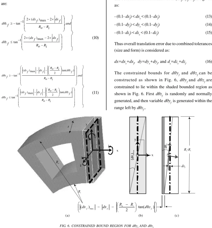
The constrained bounds for dθyf and dθzf can be constructed as shown in Fig. 6, dθyf and dθzf are constrained to lie within the shaded bounded region as shown in Fig. 6. First dθzf is randomly and normally generated, and then variable dθyf is generated within the range left by dθzf..
(a) (b) (c)
Similarly, dθxf is constrained to lie within the region as
shown in Fig. 7, and is generated as normally distributed
random variable within this range.
8.
RESULTS AND DISCUSSION
In order to minimize assembly variations in circular-build
structure (such as aero engine), assembly variation
propagations are calculated and analyzed for comparison.
Stage-by-stage assembly variations are calculated at all
possible mating combinations of the components. The
accumulated errors are calculated in three degrees of
freedom of translation error at each mating position. Error
norm ( e ) is calculated to see overall level of assembly
variation propagations. The error norm for circular-build
assembly can be defined as the RMS (Root Mean Square)
error in radial direction. Mathematically error norm can be
described as follows:
(
)
∑ =
= n
i R Error i e
1
2 )
( (17)
Where e is the error norm, n=number of component (ten
components in this case study), and R(Error)i is the assembly
error in radial direction at ith stage. R
(Error)i can be calculated
as:
2 2 )
(Error i dxi dyi
R = + (18)
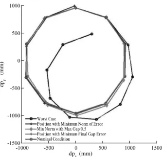
The assembly results are analyzed and compared based
on three different criteria of selecting mating sequence.
In first criteria, the component mating sequence that gives
minimum error norm is considered and the corresponding
error values are calculated. Second criteria compare the
mating sequence which gives minimum norm with
maximum gap of 0.5mm gap at the end of assembly. In
second criteria, only those mating sequences are
compared which give the final gap value less than or
equal to 0.5mm. Third criteria compare the mating
sequence which gives minimum gap at the end of
assembly. In this criteria, it is considered that there is
always gap after the assembly of final component, any
assembly which give interference is avoided. The results
of three criteria are compared with nominal assembly as
well as the worst case mating sequence. Worst case error
propagations are calculated to see how random assembly
may lead to the assembly out of specification. For worst
case, assembly variations are calculated for that mating
sequence of the components which give maximum value
of norm of stage-by-stage error.
Fig. 8 shows that the three criteria have enough potential
to reduce assembly variation. The Criteria-1, Criteria-2,
and Criteria-3 gives 61, 48, and 53% of reduction of
error compared to worst case respectively. Fig. 9 also
reveals that the three criteria of selecting mating
sequence have resulted in significant difference of radial
error reduction.
9.
CONCLUSION
An optimum mating sequence strategy for circular-build assembly structures has been presented. The results are calculated for three different criteria and these results are
compared for validation with worst case assembly mating sequence. The three criteria have enough potential to reduce stage by stage variation propagation in circular-build assembly structures. Since, the input design variables are randomly generated as normally distributed variables, and with every different set of input design variables the results may vary from those shown in this paper.
ACKNOWLEDGMENTS
The authors would like to express their sincere thanks to Experts/Reviewers of this paper for their detailed review and advice, in order to improve the quality of the paper.
REFERENCES
[1] Webb, P., Jayaweera, N., Ye, C., and Johnson, C., "Robotic Assembly of Aero-Engine Components", Aerospace Manufacturing and Automated Fastening Conference & Exhibition, North Charleston, SC, USA, 2008.
[2] Jayaweera, N., Webb, P., and Johnson, C., "Measurement Assisted Robotic Assembly of Fabricated Aero-Engine Components", Assembly Automation, Volume 30, No. 1, pp. 56-65, 2010.
[3] Mansoor, E.N., "Selective Assembly - Its Analysis and Applications", International Journal of Production Research, Volume 1, No. 1, pp. 13-24, 1961.
[4] Matsuura, S., and Shinozaki, N., "Optimal Process Design in Selective Assembly when Components with Smaller Variance are Manufactured at Three Shifted Means", International Journal of Production Research, Volume 49, No. 3, pp. 869-882, 2011.
[5] Hussain, T., Yang, Z., Popov, A.A., and McWilliam, S., "Straight-Build Assembly Optimization: A Method to Minimize Stage-by-Stage Eccentricity Error in the Assembly of Axisymmetric Rigid Components (Two-Dimensional Case Study)", ASME Journal of Manufacturing Science and Engineering, Volume 133, No. 3, pp. 031014, 2011.
[6] Mantripragada, R., and Whitney, D.E., "Modeling and Controlling Variation Propagation in Mechanical Assemblies using State Transition Model", IEEE Transactions on Robotics and Automation, Volume 15, No. 1, pp. 124-140, 1999.
[7] Yang, Z., Hussain, T., Popov, A.A., and McWilliam, S., "Novel Optimization Technique for Variation Propagation Control in an Aero-Engine Assembly", Proceedings of the Institution of Mechanical Engineers, Part-B, Journal of Engineering Manufacture, Volume 225, No. 1, pp. 100-111, 2011.
FIG. 8. COMPARISON OF RADIAL ERRORS (THE ERRORS SHOWN ARE EXAGGERATED VALUE OF ACTUAL ERROR BY
FACTOR 10X)
FIG. 9. AMPLITUDE OF RADIAL ERROR STAGE-BY-STAGE (THE ERRORS SHOWN ARE EXAGGERATED VALUE OF
ACTUAL ERROR BY FACTOR 10X)
dp
y
(mm)
dpx (mm)
dp
y
(mm)
[8] Dabling, J.G., "Incorporating Geometric Feature Variation with Kinematic Tolerance Analysis of 3D Assemblies", M.Sc. Thesis, Brigham Young University, Provo, Utah, USA, 2001.
[9] Yang, Z., Hussain, T., Popov, A.A., and McWilliam, S., "A Comparison of Different Optimization Techniques for Variation Propagation Control in Mechanical Assembly", IOP Conference Series: Materials Science and Engineering, Volume 26, No. 1, pp. 1-11, 2011.
[10] Roy, U., and Li, B., "Representation and Interpretation of Geometric Tolerances for Polyhedral Objects-I Form Tolerances", Computer-Aided Design, Volume 30, No. 2, pp. 151-161, 1998.
[11] BSI, DD CEN ISO/TS 17450-1, "Geometric Product Specifications (GPS)-General Concepts; Part-1: Model for Geometrical Specification and Varification", Brussels, 2007.
[12] Mantripragada, R., Cunningham, T.W., and Whitney, D.E., "Assembly Oriented Design: A New Approach to Designing Assemblies", Proceedings of the Fifth IFIP TC5/WG5.2 International Workshop on Geometric Modeling in Computer-Aided Design, pp. 308-324, USA, 1997.
[13] Paul, R.P., "Robot Manipulators: Mathematics, Programming, and Control", The MIT Press, USA, 1981.
[15] Behara, R.S., Fontenot, G.F., and Gresham, A., "Customer Satisfaction Measurement and Analysis using Six Sigma", International Journal of Quality & Reliability Management, Volume 3, pp. 9-18, 1995.