ISSN: 1546-9239
©2012 Science Publication
doi:10.3844/ajassp.2012.2012.2020 Published Online 9 (12) 2012 (http://www.thescipub.com/ajas.toc)
Corresponding Author: Muruganantham, Department of Electrical and Electronics Engineering,Faculty of Engineering, Periyar Maniammai University, Thanjavur (d.t), Tamil Nadu, India
GENETIC BASED PLUS INTEGRAL
CONTROLLER FOR PMBLDC MOTOR
CONTROL USING RESONANT POLE INVERTER
1
Muruganantham and
2Palani
1
Department of Electrical and Electronics Engineering,
Faculty of Engineering, Periyar Maniammai University, Thanjavur (d.t), Tamil Nadu, India 2
Department of Electronics Engineering,
Faculty of Engineering, Sudharsan Engineering College, Sathiyamangalam, Pudukkottai (d.t), Tamil Nadu, India
Received 2012-09-15, Revised 2012-12-19; Accepted 2012-12-19
ABSTRACT
Permanent Magnet Brushless DC (PMBLDC) motor drives are increasingly popular in industrial applications due to rapid progress of technologies in power electronics and the growing demand for energy saving. The increasing demand of energy saving from society is the external force for the development of PMBLDC motor drives. It is however driven by a hard-switching Pulse Width Modulation (PWM) inverter, which has low switching frequency, high switching loss, high Electro-Magnetic Interference (EMI), high acoustic noise and low efficiency, etc. To solve these problems of the hard-switching inverter, many soft-switching inverters have been designed in the past. Unfortunately, high device voltage stress, large dc link voltage ripples, complex control scheme and so on are noticed in the soft-switching inverters. This study introduces a novel genetic-proportional Plus Integral (PI) controller based resonant pole inverter using transformer, which can generate dc link voltage notches during chopping which minimize the drawbacks of soft-switching. Hence all switches work in zero-voltage switching condition. The performance of the genetic-based PI controller is compared with conventional PI controller. The experimental results show that the genetic-based PI controller renders a better transient response than the conventional PI controller resulting in negligible overshoot, smaller settling time and rise time. Moreover the proposed controller provides low torque ripples and high starting torque. Both simulation and experimental results are presented to show the superiority of the proposed GA-PI controller based resonant pole inverter.
Keywords: Brushless DC Motor, Genetic-Based PI Controller, Resonant Pole Inverter, Zero-Voltage Switching, Zero-Current Switching
1. INTRODUCTION
Brushless DC Motor (BLDCM) has been broadly used in drive systems and servo control because of its fast response, high power density, high efficiency, low inertia, high reliability and maintenance free. The operating characteristics of Brushless Dc (BLDC) motor resemble that of a conventional commutated dc permanent magnet motor but without the mechanical commutators and brushes. Hence many problems associated with brushes such as radio-frequency interference and sparking which is the potential source of ignition inflammable atmosphere are eliminated. It is usually supplied by a hard switching Pulse Width Modulation (PWM) inverter, which normally has
relatively low efficiency since the power losses across the switching devices are high. The high dv/dt and di/dt will result in severe Electromagnetic Interference (EMI) and rigorous problems with the reverse recovery of the freewheeling diodes, especially in high switching frequency. As the switching frequency of the hard switching is not very high when the switching frequency is within audio spectrum, it may produce severe acoustic noise. In order to solve these problems, many soft switching inverters have been designed in the past but it has its own limitation (Muruganantham and Palani, 2011).
implementation, good performance and feasibility for most of the systems. But the performance of these controllers is directly related with the suitable selection of their parameters such as Kp and Ki. Normally these parameters are determined in a trial and error approach or using conventional techniques such as Ziegler-Nichols (Ziegler and Nichols, 1942), root-locus, etc. However, these methodologies consider that the plant is time-invariant with a specific set of fixed parameters and are likely to change due to aging and operating conditions as a result of which the response gets deteriorates. Thus, the controller with its parameters tuned previously for the original plant and/or setpoint will have the performance depreciated. The solution for this problem of PI performance is to retune the parameters. This retuning can be made on-line or off-line (Astrom and Hagglund, 1995). The on-line tuning is done when the minimum acceptable performance is not reached, makes the search of new parameters periodically. This technique is necessary mainly to those plants whose parameters change frequently. It is efficient but needs a better hardware, because it is computationally intensive. For plants where the parameter variations are not so fast, the off-line tuning is a good option. In such a case, the retune is made only when the operator judges that it is necessary. Although it is also computationally intensive, the calculation does not have to be done in hardware (embedded systems). To assure an independent good performance, the controller must be able to adapt the changes of plant dynamic characteristics. For these reasons, it is highly desirable to increase the capabilities of PI controllers by adding new features. Many random search methods, such as Genetic Algorithm (GA) have recently received much interest for achieving high efficiency and searching global optimal solution in problem space (O’Mahony et al., 2000; Varsek et al., 1993) such as the search of optimal PI controller parameters.
In this study, a new genetic-PI controller based resonant pole inverter is designed for BLDC motor drive systems which is easy to implement in industries and it has the advantages of low switching power loss, low inductor power loss, low dc link voltage ripple, small device voltage stress, low switching noise and simple control scheme. Moreover the system provides low torque ripples, high starting torque, better transient response resulting in negligible overshoot, smaller settling time and rise time.
2. RESONANT POLE INVERTER
TOPOLOGY
The schematic diagram of the proposed genetic-PI controller based resonant pole inverter for BLDC motor
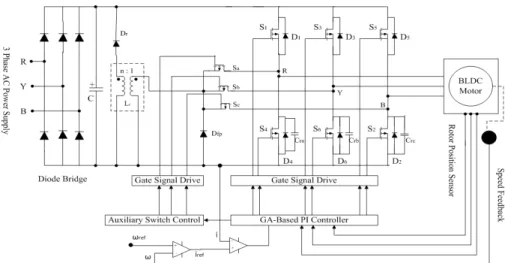
drive system is shown in Fig. 1. Each pole comprises a resonant inductor and a resonant capacitor at each phase leg. These capacitors are directly connected in parallel to the main inverter switches in order to achieve Zero-Voltage Switching (ZVS) condition. In contrast to the resonant dc link inverter, the dc link voltage remains unaffected during the resonant transitions. The resonant transitions occur separately at each resonant pole when the corresponding main inverter switch needs switching. Therefore the main switches in the inverter phase legs can switch independently from each other and choose the commutation period without restraint. Moreover, there is no additional main conduction path switch. Thus, the normal operation of the resonant pole inverter is entirely the same as that of conventional hard switching inverter. The rotor position is sensed by a Hall Effect sensor or a slotted optical disk, providing three square waves with phase shift of 120º. These signals are decoded by a combinatorial logic (Miller, 1989) to provide the firing signals for 120º conduction on each of the three phases. The three upper switches work under commutation frequency (several hundred Hz) and the three lower switches work under PWM frequency (tens of kHz). So it is not important that the three upper switches work under soft switching condition.
The system contains a diode bridge rectifier, a resonant circuit, a conventional 3Ф inverter and control circuitry. The resonant circuit consists of three auxiliary switches (Sa, Sb, Sc), one transformer with turns ratio 1 : n and two diodes Dfp, Dr. Diode Dfp is connected in parallel to the primary winding of the transformer and diode Dr is serially connected with secondary winding across the dc link. There is one snubber capacitor connected in parallel to each switch of phase leg. The snubber capacitor resonates with the primary winding of the transformer. The emitters of the three auxiliary switches are connected together. Thus, the gate drive of these auxiliary switches can use one common output dc power supply. The turns ratio (1: n) of the transformer, equivalent inductance of the transformer, snubber capacitance and whole switching transition time is determined from (Zhi and Luo, 2005). Main switches S1 to S6 work under ZVS condition and therefore the voltage stress is equal to the dc link voltage Vs. The device current rate can be load current.
Fig. 1. Schematic diagram of the proposed genetic-PI controller based resonant pole inverter for BLDC motor
Fig. 2. Gate signals GS4,6,2 and GSa,b,c from G4,6,2 The gate signals of three lower main inverter switches
and auxiliary switches can be deduced from the output G4,6,2 as shown in Fig. 2. The trailing edge of the gate signals for three lower main switches GS4,6,2 is same as that of G4,6,2, the leading edge of GS4,6,2 lags behind G4,6,2 for a short time T1. The gate signals for auxiliary switches GSa,b,c have a fixed pulse width ( T2) with the leading edge, the same as that of G4,6,2.
3. PROPORTIONAL INTEGRAL
CONTROLLER
The model of PI speed controller is given by Equation 1:
i p
K G(s) K
s
= + (1)
(
p i)
p2 i
K s K / J T(s)
B K K
s s J J + = + + + (2)
where, T(s) is the closed loop transfer function and Kp, Ki are the PI controller parameters, J is the moment of inertia and B is the coefficient of friction of the BLDC motor. Comparing the characteristic Equation 2 of the transfer function with Equation 3 and 4:
p n
K = ξω −2 J B (3)
2
i n
K = ωJ (4)
4. GENETIC-BASED PI CONTROLLER
The Genetic Algorithm (GA) was inspired by the mechanism of natural selection, a biological process in which stronger individual is likely to be the winners in a challenging environment. GA uses a direct analogy of such natural evolution to do global optimization in order to solve highly complex problems (Goldberg, 1989). In the beginning, an initial chromosome population is randomly generated. The chromosomes are candidate solutions to the problem. Then, the fitness values of all chromosomes are evaluated by calculating the objective function in a decoded form. So, based on the fitness of each individual, a group of the best chromosomes is selected through the selection process. In each generation, the genetic operators are applied to selected individuals from the current population in order to create a new population. Generally, the three main genetic operators namely reproduction, crossover and mutation are employed. By using different probabilities for applying these operators, the speed of convergence can be controlled. Crossover and mutation operators must be carefully designed, since their choice highly contributes to the performance of the whole genetic algorithm.
4.1. Reproduction
A part of the new population can be created by simply copying without any change in the selected individuals from the present population. Also new population has the possibility of selection by already developed solutions. There are a number of other selection methods available and it is up to the user to select the appropriate one for each process. All selection methods are based on the same principle i.e. giving fitter chromosomes a larger probability of selection. Here Roulette Wheel selection method is used.
4.2. Crossover
New individuals are generally created as offspring of two parents (i.e., crossover being a binary operator). One or more so called crossover points are selected (usually at random) within the chromosome of each parent, at the same place in each. The parts enclosed by the crossover points are then interchanged between the parents. The individuals resulting in this way are the offspring.
4.3. Mutation
A new individual is created by making modifications to one selected individual. The modifications can consist of changing one or more values in the representation or adding/deleting parts of the representation.
4.4. Objective Function
The most essential step in applying GA is to choose the objective functions that are used to evaluate fitness of each chromosome. The objective function is Integral of the Squared Error (ISE) (Zwe-Lee, 2004; O’Mahony et al., 2000) Equation 5:
0 ISE e(t)dt
τ
=
∫
(5)
4.5. Fitness Values
The PI controller is used to minimize the error signal, or define more rigorously, in the term of error criteria: to minimize the value of performance indices mentioned below. Since smaller the value of performance indices of the corresponding chromosomes the fitter the chromosomes will be and vice versa, the fitness value of the chromosomes is expressed as Equation 6 (O’Mahony et al., 2000; Teng et al., 2003):
1 Fitness value
Performance Index
= (6)
From above introduction, GA is a search algorithm that continuously repeats these steps: Reproduction, Crossover and mutation, then make the new generation fitter than the old generation, until the requirements are completed. So in this study GAS are used to optimize PI parameters KpandKi. First, Kp and Kiare encoded to 16 bits string (Fliess and Join, 2008) as:
p
i
K : 1010110011101011
Table 1. The parameters of BLDC motor
Parameters Value
Rated input voltage Vin 24 V Rated armature current Ia 10.4 A
Rated speed N 1500 rpm
Armature resistance Ra 0.3 Armature inductance La 1.15 mH Magnetic flux linkage Ф 0.20wb
No. of poles P 4
Moment of inertia J 0.002 kg.m2 Friction factor F 0.0001Nm.s/rad
Table 2. The parameters of genetic algorithm
Parameters Value
Population size 30
Generation number 250
Selection method Roulette wheel
Crossover probability 85%
Mutation probability 0.20%
Table 3. Performance analysis of PI and genetic based PI controller
Controllers GA-
parameters PI Based PI
Delay Time (sec) 0.096 0.062
Rise Time (sec) 0.190 0.091
Peak Time (sec) 0.238 0.120
Percentage Overshoot (%) 0.266 0.00 Settling Time (sec) 0.270 0.12 Starting Torque (Nm) 1.700 6.90 Torque Ripples (Nm) ± 0.200 ± 0.10
The length of total chromosome is 32 bits. It is supposed that Kp and Ki are bounded in the closed intervals [0 Kpm] and [0 Kim] respectively. The decimal values of their corresponding binary strings are linearly related to their range boundaries Kpm and Kim. Secondly, according to GAS operation: evaluation, crossover, mutation, Kp and Ki are optimized. After a prescribed number of generations, Kp and Ki are suitable enough to make system have good steady-state and dynamic performance.
5. SIMULATION RESULTS
The BLDC motor parameters are shown in Table 1 and its performance is obtained by simulation using MATLAB/SIMULINK 7.5. The simulation was run for 1 sec (simulation time). The dc link voltage VS is chosen as 30 V and the maximum load current is 10 A. The transformer turns ratio is chosen as 1: 4 and the leakage inductance of the primary and secondary windings are 0.7 H and 2.8 H respectively. With the equivalent transformer inductance Lr = 1.5 H, the resonant capacitance Cr is 0.1 F. t1 + t2 + t3 is determined for various load current Io. Considering the turn off time of switch lagging ∆T1and pulse width ∆T2 they are set to 2.1 s and 5 s respectively. The frequency of the PWM is 20 kHz.
5.1. By Conventional PI Controller
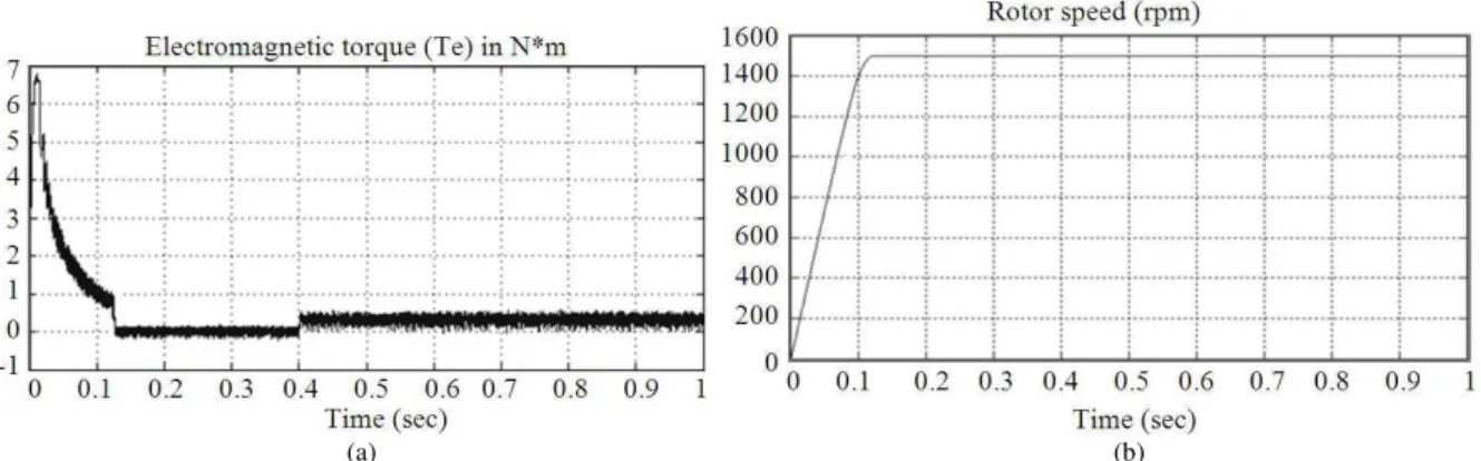
By substituting the values of the motor parameters and using Ziegler Nichols method, the tuning parameters of PI controller are determined as Kp = 3.3 and Ki = 300. The electromagnetic torque and speed response curves obtained with PI controller are shown in Fig. 3. Figure 3a shows electromagnetic torque for the reference speed of 1500 rpm and load torque is applied at 0.4 seconds. From Fig. 3a, it is observed that the starting torque is 1.7 Nm and torque ripple is with the amplitude variation of ± 0.2 Nm. From speed response curve of Fig. 3b, it is observed that the rise time is 0.19 sec, overshoot is 0.266% and settling time is 0.27 sec with PI controller.
5.2. By GA-PI Controller
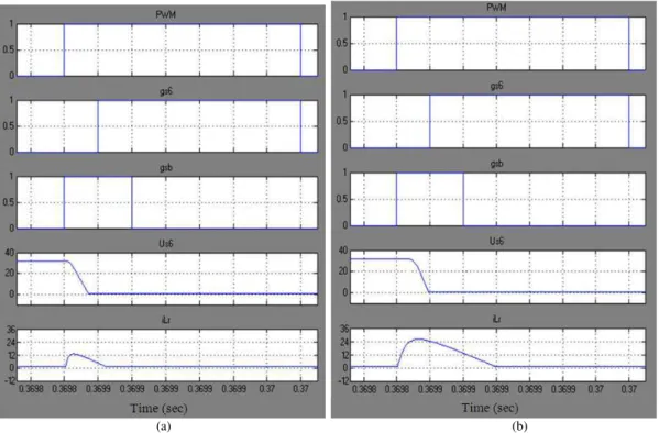
Similarly by substituting the values of the motor parameters and using genetic algorithms, the tuning parameters of genetic based PI controller are determined as Kp = 4.0639 and Ki = 0.7411. The Parameters of genetic algorithm are shown in Table 2. The electromagnetic torque response and speed response curves obtained for genetic based PI controller is shown in Fig. 4a shows electromagnetic torque for the reference speed of 1500 rpm and load torque is applied at 0.4 sec. From Fig. 4a, it is observed that the starting torque is 6.9 Nm and torque ripple is with the amplitude variation of ±0.1 Nm. From speed response curve of Fig. 4b, it is observed that the rise time is 0.091 sec, overshoot is almost eliminated and settling time is 0.12 sec with genetic based PI controller. Waveforms of PWM, main switch S6, auxiliary switch Sb gate signal, switch S6 voltage drop Us6 and transformer primary winding current iLr under low load current (Io = 3A) and high load current (Io = 10A) are shown in Fig. 5.
6. EXPERIMENTAL RESULTS
(a)
(b)
Fig. 3. (a) Electromagnetic torque and (b) speed response at1500 rpm with PI controller
(a) (b)
(a) (b)
Fig. 5. Simulation waveforms of PWM, S6,Sb gate signal, Us6 and iLr under various load current (a) low load current (Io = 3A) and (b) high load current (Io = 10A)
(a) (b) (c)
(d) (e)
(a) (b)
Fig. 7. (a) Measured no-load speed (1V = 500 rpm/div, 0.075s/div) (b) measured speed with load (1V = 500 rpm/div, 0.075s/div)
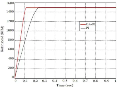
Fig. 8. Speed response curves for PMBLDC motor obtained using PI and genetic based PI controllers The system is tested in light load and full load
currents. The voltage waveforms across the main inverter switch uS6 and its gate signal in low and high load currents are shown in Fig. 6a and b, respectively. All the voltage signals are measured by a differential probe with a gain of 10. For voltage waveform, 2.00 V/div = 20 V/div. The waveforms of uS6 and its current iS6 are shown in Fig. 6c and it is observed that dv/dt, di/dt are reduced significantly. The waveforms of uS6 and transformer primary winding current iLr are shown in
Fig. 6d. The phase current is shown in Fig. 6e. From the above output waveforms, the proposed GA-PI based resonant pole inverter works very satisfactorily as expected under various load currents. Further it is observed that there is small overlap between the voltage and current waveforms during the switching under soft switching condition which ensures low power losses.
no-load starting performance from 300 to 1500 rpm. It is found that the motor drive responds quickly and takes only about 0.12 s to reach the desired speed with zero steady state error. The corresponding simulation waveform is shown in Fig. 4b for comparison. Figure 7b shows the dynamic performance due to step change in load torque from no-load to 0.3Nm load at 1500 rpm. It is observed that the drop in speed during transient is very insignificant and the speed regulation is excellent.
Figure 3b and 4b are redrawn for comparison of speed response obtained using conventional PI and GA based PI controllers and is shown in Fig. 8. The rise time, settling time, percentage overshoot, starting torque and torque ripples are considered for performance evaluation of these controllers and are shown in Table 3. From Table 3 it is evident that, the performance specifications obtained using GA based PI controller is better than those obtained using conventional PI controller. Further, it is observed that the resonant pole inverter performs better under various load currents. Furthermore soft switching condition, the switching power losses are low. This validates the resonant pole inverter topology used in this study.
7. CONCLUSION
The dynamic behavior of the BLDC drive system with conventional PI and genetic based PI controllers are presented and compared for torque and speed operation. It is observed that the genetic based PI controller gives much better dynamic response for the system. From the results of proposed inverter topology, it is observed that all the switches work under soft switching condition and freewheeling diodes are turned off under zero current condition which greatly reduces the reverse recovery problem of the diodes. Further, voltage stress on all the switches is very low and it is not greater than the dc supply voltage. The switching acoustic noise is very much reduced as the switching frequency is as high as 20 kHz. Further, dv/dt and di/dt are reduced significantly and as a result EMI is reduced. Furthermore, only very simple auxiliary switching control scheme is needed and the normal operation of the inverter is entirely the same as that of the hard switching inverter. The performance characteristics of conventional PI and genetic based PI controllers are compared interms of delay time, rise time, peak time, percentage overshoot, settling time, starting torque and torque ripples. It is observed that genetic based PI controller performs better than conventional PI controller.
8. REFERENCES
Astrom, K.J. and T. Hagglund, 1995. PID Controllers: Theory, Design and Tuning. 2nd Edn., ISA, United States, ISBN-10: 1556175167, pp: 343.
Fliess, M. and C. Join, 2008. Intelligent PID controllers. Proceedings of the 16th Mediterranean Conference on Intelligent Control and Automation, Jun. 25-27, IEEE Xplore Press, Ajaccio, pp: 326-331. DOI: 10.1109/MED.2008.4601995
Goldberg, D.E., 1989. Genetic Algorithms in Search, Optimization and Machine Learning. 1st Edn., Addison-Wesley, Reading, Mass, ISBN-10: 0201157675, pp: 412.
Miller, T.J.E., 1989. Brushless Permanent-Magnet and Reluctance Motor Drives. 1st Edn., Clarendon, Oxford, ISBN-10: 0198593694, pp: 207.
Muruganantham, N. and S. Palani, 2011. Novel soft switching inverter for brushless dc motor using fuzzy logic. Int. J. Elect. Eng., 4: 601-616.
O’Mahony, T., C.J. Downing and K. Fatla, 2000. Genetic algorithm for PID parameter optimization: Minimising error criteria. Wroclaw University of Technology.
Teng, T.K., J.S. Shieh and C.S. Chen, 2003. Genetic algorithms applied in online autotuning PID parameters of a liquid-level control system. Tran. Instit. Measur. Control, 25: 433-450. DOI: 10.1191/0142331203tm0098oa
Varsek, A., T. Urbacic and B. Filipic, 1993. Genetic algorithms in controller design and tuning. IEEE Trans. Syst. Man Cyber, 23: 1330-1339. DOI: 10.1109/21.260663
Zhi, Y.P. and F.L. Luo, 2005. Novel resonant pole inverter for brushless dc motor drive system. IEEE Trans. Power Elect., 20: 173-181. DOI: 10.1109/TPEL.2004.839814
Ziegler, J.G. and N.B. Nichols, 1942. Optimum setting for automatic controllers. ASME Trans.