(IJACSA) International Journal of Advanced Computer Science and Applications, Vol. 7, No. 12, 2016
76 | P a g e www.ijacsa.thesai.org
Model and Criteria for the Automated Refactoring of
the UML Class Diagrams
Evgeny Nikulchev
Moscow Technological InstituteMoscow, Russia
Olga Deryugina
Moscow Technological University MIREA Moscow, Russia
Abstract—Many papers have been written on the challenges of the software refactoring. The question is which refactorings can be applied on the modelling level. Based on the UML model, for example. With the aim of evaluating this possibility the algorithm and the software tool of automated UML class diagram refactoring were introduced. The software tool proposed reduces the level of the UML class diagram complexity metric.
Keywords—UML; refactoring; class diagrams; software architecture; software design; UML transformation
I. INTRODUCTION
MDA (Model Driven Architecture) [1] approach is supported by OMG (Object Management Group). In the MDA approach design process starts with the creation of the PIM (Platform Independent Model). Then the PIM is automatically transformed into the PSM (Platform Specific Model).
MDA proposes standards of model creation, transformation and exchange. For example, UML (Unified Modelling Language) [2] is used to describe models, XMI (XML Metadata Interchange) [3] is used to exchange models between tools. One tool can be used to create a model, and another one
– to analyze or transform it. Thus, model transformations play an important role in the MDA conception. One of the possible model transformation objectives can be model refactoring.
Refactoring means restructuring of the system without changing its behavior. Originally, refactoring was connected with the code-level transformations. A number of studies have investigated different means of the software refactoring [4, 5, 6].
Some refactorings apply design patterns to the existing code. First design patterns were proposed by Erich Gamma et al. in [7]. Software design patterns describe solutions of commonly occurring problems. Design patterns are aimed at the improvement of such software characteristics as modifiability, reusability, maintainability, etc.
Many papers have been written on the challenges of the software refactoring. The question is which refactorings can be applied on the PIM level described with the UML.
There are two main approaches to the problem of UML refactoring. The first one is connected with the search based software engineering [8] (SBSE), which is a topic of growing interest nowadays. In SBSE software engineering problems are formulated as optimization problems, which then are solved by search algorithms (Genetic algorithm, Simulated annealing,
Swarm intelligence algorithms, etc.) SBSE is used in order to solve UML class diagram refactoring problem in [9–14]. However, the result of applying search algorithms to class diagrams sometimes can be meaningless.
The second approach is connected with the developing frameworks of automated model refactoring [15–18], where the main role is given to the software designer. And the framework applies transformations, using some transformation rules in interaction with the designer.
This paper explores the problem of the automated UML class diagram refactoring. This problem is significant as long as the model refactoring is less time-consuming than the code refactoring. Furthermore, model refactoring is connected with the creation of PIM rather than PSM.
The rest of this paper is organized as follows: First, the problem of the automated UML class diagram refactoring is formulated in Section 2. Then an algorithm of the automated UML class diagram refactoring is proposed in Section 3. In Section 4, the software tool UML Refactoring is introduced before concluding in Section 5.
II. FORMULATION OF THE PROBLEM
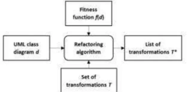
The scheme of the UML class diagram analysis is shown in Fig. 1. Algorithm takes as input UML class diagram d, fitness function f(d) and a set of semantically equivalent transformations T. The output is a list of transformations T*,
which reduce fitness function value and are recommended to apply.
Fig. 1. Scheme of the UML class diagram analysis
Let d be a UML class diagram d{C,I,R}, where C is a set of classes C{c0,...,ck}, I is a set of interfaces
}, ,...,
{i0 i1
(IJACSA) International Journal of Advanced Computer Science and Applications, Vol. 7, No. 12, 2016
77 | P a g e www.ijacsa.thesai.org
Then ci is a class ci{Ai,Mi,Fi}, where Ai is a set of
attributes { 0, 1,..., }, i n i i
i a a a
A Mi is a set of methods
}, ,..., ,
{ 0 1
i m i i
i m m m
M Fi is a set of features
} 1 , 0 { ,...}, , , {
st v abs st
Fi i i i is isStatic feature, vi is
visibility parameter vi{public,private,protected},absi is
isAbstract feature absi{0,1}.
In addition, ii is an interface which defines a set of
methods { 0, ,... }.
i m i i i
i m m m
M
Let us assume that UML class diagram transformation t can be described as the following mapping function:
, ' : ) ,
(d E d d
t (1)
where E is a set of diagram elements ei ϵd, ei ∈ {C,R,I}.
Assume that the semantically equivalent transformation t is such a transformation t(d,E): d→ d’, that:
( ) ( '),
S d S d (2)
where S(d)is a structural semantic value of the diagram d, which can be described as follows:
{...}, {
{...}}, {...},...,
{...},
{{1 2 11
c c c i
S ki
i i i }}, ,..., , { {...}},
{...},...,1 1 2
2 i m i i i i r r r i
i (3)
where c1,...,ckdi are the classes of the diagram d;
i
l d
i
i1,..., are the interfaces of the diagram d;r1,...rmdi are the relations of the diagram d.
The automated UML class diagram refactoring problem can be formulated as follows:
Assume that there is a UML class diagram d,a set of semantically equivalent transformations T, and a fitness function f(d).
Then it is required to find such a set of pairs {t,E}, that:
. 0 ) ' ( ), , (
't d E f d
d
III. AUTOMATIC UMLCLASS DIAGRAM REFACTORING
ALGORITHM
Then the CDTA (Class Diagram Transformation Analysis) Algorithm can be described as follows:
for each tϵT
L = search(t,d,f) //search pairs {t,E} for which ∆f(d’)<0 Q.add(L) //add pairs {t,E} to the resulting list
return Q
The search(t,d,f) function can be defined as follows:
L1 = analyze(t,d) //search element sets E ∈d for the
transformation for each eϵL1
d’ = refactor e,t,d //apply transformation t to the
diagram d
if f d’ < f d //check the decrease of the f(d) value
L2.add(t,e) //add t and e to the resulting list
return L2
The analyze (t,d) method is specific for each transformation. For example, the algorithm of searching sets of diagram elements E on which the Strategy transformation can be conducted can be described as follows:
1) Make a list of classes having inheritors l1.
2) 2. For each class from l1 check whether its inheritors implement any interfaces. If yes – add them to the list l2.
3) 3. For each class from l1 calculate K(d) . If
0 )
(
K d – add to the list l3: {parent_id,
{child_classes_ids},{interfaces_ids}}.
4) 4. Return l3.
Let us formulate an example of the fitness function – structural complexity metric K(d):
n i n i ii k M
A k R k I k C k d K
0 5 0
4 3
2
1| | | | | | | | | |
) (
m
i Mj
k6 0| '|, (4)
where K(d)is the structural complexity of the diagram d;
|
|C is the number of classes
;
d ci
|
|I is the number of
interfaces
;
d
ii |R| is the number of relations rid; Ai is a set of attributes ajci,cid;Mi is a set of class methods (except of the methods, declared in implemented interfaces)
;
,c d
c
mi i i Mj' is a set of interface methods
; ,i d i
mji i k1,k2,k3,k4,k5,k6 are weights for each group of
elements.
IV. UMLCLASS DIAGRAM REFACTORING TOOL
Class diagram refactoring software should solve the following tasks:
1) UML class diagram analysis: searching the transformations which can be conducted to decrease the fitness function value;
2) UML class diagram transformation.
(IJACSA) International Journal of Advanced Computer Science and Applications, Vol. 7, No. 12, 2016
78 | P a g e www.ijacsa.thesai.org
Fig. 2. Functional blocks of the UML class diagram refactoring tool
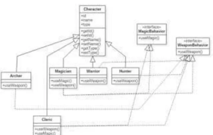
Let us introduce an example of applying the UML refactoring tool to the class diagram d shown in Fig. 3.
Assume that it is required to minimize relations count value. First, weight values for the fitness function should be set: k10.01;k20.01;k31;k40.01;k50.01;k60.01.
Then it is attained, that:
. 19 . 12 02 . 0 06 . 0 03 . 0 12 02 . 0 06 . 0 )
(d
K
Fig. 3. Initial UML class diagram d
The UML Refactoring tool proposes the following transformations (see Fig. 4):
Interface insertion for the classes Magician, Cleric and for methods useWeapon(), useMagic();
Strategy insertion for the interfaces MagicBehaviour, WeaponBahaviour, parent class Character and child classes Archer, Magician, Warrior, Hunter, Cleric.
Fig. 4. Transformations proposed by the UML refactoring tool
The result of applying the Strategy transformation to the diagram d is shown in Fig. 5 and Fig. 6.
Fig. 5. The result of applying the Strategy transformation to the diagram d After the transformation, the following is attained:
, 23 . 7 02 . 0 08 . 0 05 . 0 7 02 . 0 06 . 0 ) '
(
K d
. 96 . 4 )
(
K d
Fig. 6. Diagram d’ attained as the result of the Strategy transformation
V. CONCLUSIONS
The presented framework gives the possibility to analyze and automatically restructure UML class diagrams in accordance with aims of the refactoring, which can be formulated based on the fitness function (4).
The main role is given to the software designer, who can import/export UML class diagrams in XMI format, refactor them and save the results.
The framework calculates metrics and proposes a list of transformations, which minimize the fitness function value. Available transformations include Strategy, Façade, Interface insertion, etc.
(IJACSA) International Journal of Advanced Computer Science and Applications, Vol. 7, No. 12, 2016
79 | P a g e www.ijacsa.thesai.org
REFERENCES
[1] OMG Model Driven Architecture (http://www.omg.org/mda)
[2] OMG Unified Modelling Language UML. Version 2.5 (http://www.omg.org/spec/UML/2.5)
[3] XML Metadata Interchange (XMI) Specification. Version 2.4.2 (http://www.omg.org/spec/XMI/2.4.2)
[4] J. Kerievsky, “Refactoring to Patterns. Boston M. A.: Addison-Wesley, 2004.
[5] M. Fowler, Refactoring: Improving the Design of Existing Code”, Boston M. A.: Addison-Wesley, 2000.
[6] T. Mens, T. Tourwe, “A survey of software refactoring”, IEEE Transactions on Software Engineering, vol. 30, no. 2, 2004, pp. 126 – 139.
[7] E. Gamma, H. Richard, J. Ralph, and V. John, “Design patterns: Abstraction and reuse of object-oriented design”, Springer Berlin Heidelberg, 1993.
[8] M. Harman, S. Mansouri, Y. Zhang, “Search-based software engineering: Trends, techniques and applications”, ACM Computing Surveys, vol. 45, no. 1, 2012.
[9] M. Amoui, S. Mirarab, S. Ansari and C. Lucas, “A genetic algorithm approach to design evolution using design pattern transformation”, International Journal of Information Technology and Intelligent Computing, vol. 1, 2006, pp. 235 – 245.
[10] M. Bowman, L. Briand, and Y. Labiche, “Solving the class responsibility assignment problem in object-oriented analysis with multi-objective genetic algorithms”, Technical report SCE-07-02, Carleton University.
[11] S. Hadaytullah, Vathsavayi, O. Räihä, and K. Koskimies, “Tool support for software architecture design with genetic algorithms”, Proceedings
of ICSEA’10. IEEE CS Press, August 2010, pp. 359–366.
[12] R. Lutz, “Evolving good hierarchical decompositions of complex systems, Journal of Systems Architecture”, vol. 47, 2001, pp. 613 – 634 [13] C. Simons C., I. Parmee, “Single and multi-objective genetic operators
in object-oriented conceptual software design”, Proceedings of the
Genetic and Evolutionary Computation Conference (GECCO’07), 2007, pp. 1957 – 1958.
[14] O. Deryugina, "Improving the structural quality of UML class diagrams with the genetic algorithm", 6th Seminar on Industrial Control Systems: Analysis, Modeling and Computation, vol. 6., 2016, art. 03003. [15] Y. Rhazali, Y. Hadi, A. Mouloudi, “A Model Transformation According
Model Driven Architecture”, Proceedings of 3rd International Conference on Computing Engineering & Enterprise Management (ICCEEM-2015), 2015, pp. 6 – 14.
[16] Y. Rahmounea, A. Chaoui, E. Kerkouche, “A Framework for Modeling and Analysis UML Activity Diagram using Graph Transformation”, International Workshop on the Use of Formal Methods in Future Communication Networks (UFMFCN 2015), 2015, pp. 612 – 617. [17] E. Kerkouche, A. Chaoui, E. Bourennane, O. Labbani, “A UML and
Colored Petri Nets Integrated Modeling and Analysis Approach using Graph Transformation”, Journal of Object Technology”, vol. 9, no. 4, 2010. pp. 25–43.
[18] Sergievskiy Maxim, “N-ary relations of association in class diagrams: design patterns,” International Journal of Advanced Computer Science and Applications, vol. 7, no. 2, 2016, pp. 265-268.