Fiabilitate si Durabilitate - Fiability & Durability No 1/ 2015
Editura “Academica Brâncuşi” , Târgu Jiu, ISSN 1844 – 640X
37
ANALYSIS OF THE MECHANICAL STRENGTH OF A DRIVING
MECHANISM CALLED SHOCK
Prof. phd. eng. Dan ILINCIOIU
University of Craiova, Faculty of Mechanics,Department of Applied Mechanics and Civil Constructions, Calea Bucuresti Street, no.107, Craiova,Code 200512, Romania,
Eng. Cosmin MUSCALAGIU
University of Craiova, Faculty of Mechanics, Calea Bucuresti Street, no. 107,Craiova,Code 200512, Romania, [email protected]
Assistant Phd. Eng. Cosmin-Mihai MIRIŢOIU
University of Craiova, Faculty ofMechanics, Department of Vehicles, Transports and Industrial Engineering, CaleaBucuresti Street, no. 107, Craiova,Code 200512, Romania,
Abstract. It evaluates the maximum static and dynamic stresses produced in the elements of a quadrilateral
mechanism transporting a vehicle in the storage in an urban park. Determine multiplier shock hazard if the mechanism freezes and increases mechanical stress.
Keywords. Parking the car, actuators, shock requests, optimizations.
1. Defining the problem
Fiabilitate si Durabilitate - Fiability & Durability No 1/ 2015
Editura “Academica Brâncuşi” , Târgu Jiu, ISSN 1844 – 640X
38
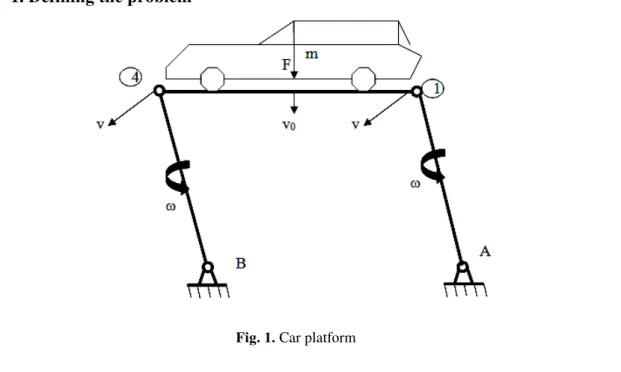
It examines platform transport a car in the modular storage in a multi-storey car park. The system is essentially a two beams oscillating platform articulated according to data in figure 1. Scheme for calculating the strength of the structure is given in Figure 2.
Kinematic parameters required are:
T
0,5 , vr
notations:- speed swing angle bars;T- time lowering the car; r- oscillatory length;
Fig.2. Calculus scheme
The masses in motion are:
car table: M=
g F g
F F
2
1 ; platform table: m=m
0l; oscillating bar table: m1=m0 r;
Ratings: F-weight car; g-gravitational acceleration , m0-specific mass of the beams.
It will define only the reactions required for resistance calculation (calculation is not complete).
2. Static analysis
In terms of balancing the moments on the platform, the reactions are (neglecting the masses platform).
V1=
( ) ( )
1
2 1 l a F l b
F
l , F1=kF , F2=(1-k)F
V2=
Fa Fb
l 1 2
1
(1)
It will take into account only the request in bending. Platform moment equations are:
Fiabilitate si Durabilitate - Fiability & Durability No 1/ 2015
Editura “Academica Brâncuşi” , Târgu Jiu, ISSN 1844 – 640X
39
If either of the oscillating bars are locked in lower joint, the bar will be requested blocked and bending moment was:
M1=V1sinx sau M2=V2 sinx (3) It defining the mechanism bars: the moment of inertia Ix, modulus Wx, m0-specific mass.
The masses bars are:
m=lm0 , m1=rm0 (4) Tensions are likely maximum:
x x W a V W M 2 1 2 ; x x W a b F b V W
M3 1 1( )
3 ; x W r
V
1 sin
1 ;
x
W r
V
2 sin
4 ; (5)
3. Shock calculation
It requires a locking mechanism during collaboration, causing an increase in the mechanical stresses. Impact multiplier is calculated using the equation:
K
1 1 , K
pc c
E E
; (6)
notations are: Ec-kinetic energy of the moving masses, Ep- the potential energy stored in
mechanism elements.
Define 3 cases blocking the movement: 1.platform blocking horizontal direction; 2.rocker blocking A-1 in the lower joint; 3.rocker blocking B-4 in the lower joint; It will calculate the multiplier in 3 cases.
3.1.Blocking Case 1. The kinetic energy is:
2 1 0,5( m) v
g F
Ec (7)
Potential energy due to bending deformation is:
a
b
a
l
b x
x
p M dx M dx M dx
I E dx M I E E 0 2 34 2 23 2 12 2 1 2 1 2 1 (8)
Replacing the timing relationship and make the integrals, parenthesis in equation (8) is calculated with equation (9).
k a l b k b b k a b l a b k a l b k b a b kl
l F
I
( ) ( ) ( 2 ) ( ) ( )
3 2 3 2 2 2 1 +
+
3 2
2 2 ) ( ) (
3 l l b k a b k b
F
Fiabilitate si Durabilitate - Fiability & Durability No 1/ 2015
Editura “Academica Brâncuşi” , Târgu Jiu, ISSN 1844 – 640X
40
Potential energy is:
x p I E I E 2 1
1 (10)
E-modulus of elasticity of the material
1 1 1 1K
, K1=
1 1 p c E E (11)
Maximum dynamic tensions are:
1 2 2
d , 3d 31 (12)
3.2.Blocking Case2 The kinetic energy is:
Ec2=0,5 m 0,25m1 v2
g F
(13)
Potential energy stored in the elements of the mechanism is:
Ep2= ( )
2 1 2 0 2 1 1
2
v A p x x dx M E I E I E I (14)
After performing the integral bracket of equation (14) is calculated using the equation:
I2= 2
2
3 l F
{(ka-l+b-kb) 2
(b3+v3sin2)+k(a-b)2[l(ka-l+b-kb)(a+2b)-kl2(a-b)]+(l-b)3(ka+b-kb)2(15)
Dynamic tensions are:
, 1
1 2
2 K
K2=
2 2 p c E E
; 2d 2 2; 3d 23; 1d 2 1; (16)
3.3.Blocking Case 3
The kinetic energy is similar to the previous situation: Ec3=Ec2
Potential energy is:
Ep3= ( )
2 1 2 0 2 2 1
3
r p x x dx M E I E I E I (17)
Parenthesis in equation (17) is calculated using the equation:
I3= 2
2
3 l F
{(ka-l+b-kb) 2
b3+k(a-b)2[l(ka-l+b-kb)(a+2b)-kl2(a-b)]+(ka+b-kb)2[(l-b)3+r2sin2] (18)
Dynamic stresses are calculated:
3 3 1 1K
, K3=
3 3 p c E E (19) 2 3 2
Fiabilitate si Durabilitate - Fiability & Durability No 1/ 2015
Editura “Academica Brâncuşi” , Târgu Jiu, ISSN 1844 – 640X
41
3.4.Evaluation of a particular case
We adopt dimensions: l = 400cm, a = 80cm, 300cm b = r = 180cm (20) Full displacement (vertical-horizontal) will be in T = 30s, resulting kinematic parameters:
= rad s
T 0,052 /
5 , 0
, v=r=9,42cm/s (21)
Rolling mechanism is adopted to build IPE200 type that has the following characteristics: Ix=1940cm4, Wx=194cm3, m0=0,224 kg/cm (22)
The position of the center of gravity of the vehicle and its weight are:
F=2000daN, K=0,4, g=1000cm/s2, F1=KF=800daN, F2(1-K)F=1200daN (23)
Maximum voltages are (it is thought that = 0,5):
1=872daN/cm2, 2=387daN/cm2, 3=546daN/cm2, 4=983daN/cm2 (24)
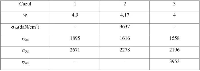
Dynamic stresses calculated with shock multipliers are given in Table 1.
Table 1
Cazul 1 2 3
4,9 4,17 4
1d(daN/cm2) - 3637 -
2d 1895 1616 1558
3d 2671 2278 2196
4d - - 3953
4. Conclusions
Defined mathematical model for assessing static voltages and multipliers shock for threecases blocking transport mechanism. Under quasi-static stress mechanical stresses are relatively small, lower value (considerated admissible) of 100daN /cm2 (100MPa).
If it is assumed that the mechanism is made of steel S235 (blood flow c = 235Mpa =
2350daN /cm2), static requirements are much lower blood flow.
It compares the 3 cases and found that the rod-platform is the most disadvantaged in case 1, the multiplier having the maximum value, the maximum voltage exceeds the yield, so it is necessary to increase the time of descent from T = 30s to 50 or 60 seconds (blood decreases maximum 1890 daN /cm2).
Fiabilitate si Durabilitate - Fiability & Durability No 1/ 2015
Editura “Academica Brâncuşi” , Târgu Jiu, ISSN 1844 – 640X
42
swing over the yield required, so it must necessarily bar to rotate freely. It is possible that in other specific conditions (size, strength, speed, material, etc) comparative analysis of requests and cases lead to other conclusions. The mathematical model being defined parameters, numerical determinations allow complete and easy.
Acknowledgement
This work was supported by the strategic grant POSDRU/159/1.5/S/133255, Project ID 133255 (2014), co-financed by the European Social Fund within the Sectorial Operational Program Human Resources Development 2007-2013.
References
[1].Ilincioiu, D, Miritoiu, C, Strength of materials,vol.II,Ed. SITECH, Craiova 2012. [2].Tripa, P, Strength of materials, Ed. MIRTON, Timisoara 2001.
[3].Muscalagiu, C, Ilincioiu, D, Report 3 doctorate, Craiova 2015.