Reduction of Bumblebee Noise Generated by
GSM
Han Su Kyi
1, Chaw Myat Nwe
2, and Hla Myo Tun
3 1 23Department of Electronics Engineering
12 3 Mandalay Technological University
Abstract- This research work presents a method for reducing a bumblebee noise generated by a GSM system. Global smart phone penetration has been very swift and 2nd generation, 3rd generation and 4th generation communication technology are commercially used in the world. GSM technology uses a channel access method that combines frequency division multiple access (FDMA) and time division multiple access (TDMA). There are four commercial frequency bands. GSM technology has a burst structure by a TDMA method. And hence, the GSM technology has a disadvantage; radiation noise is generated from an antenna propagation signal of the smart phone, and consequently, the voice quality of the smart phone is degraded. This noise is commonly known as bumblebee noise, buzz noise or TDMA noise. There have been several studies to reduce the noise since a release of GSM technology in a commercial market. Those studies mainly focused on designing infinite impulse response (IIR) notch filters by the signal processing technology or on data burst transmission schemes.
Keywords – Reduction Algorithm, Bumblebee Noise, GSM, MATLAB, Digital Filter Design
I. INTRODUCTION
Smart phones can communicate using just one time slot out of the eight time slots. This is the burst structure of the GSM. That is, an antenna signal from the smart phone is propagated through air for only 0.577ms out of the total period of 4.615ms. Because of TDMA, the GSM technology has a disadvantage; radiation noise is generated from an antenna propagation signal of the smart phones, and consequently, the voice quality of the smart phones is degraded. This noise is commonly known as bumblebee noise or buzz noise.
Several studies were carried out to develop methods for reducing bumblebee noise. Those studies mainly focused on designing infinite impulse response (IIR) notch filters by the signal processing technology [1–4] or on data burst transmission schemes [5]. The first method needs more million instructions per second (MIPS) for operation, and hence, current consumption increases accordingly. The latter method requires a change in the protocol standard of the GSM; hence, its feasibility is low.
II. BUMBLEBEE NOISE
IJECSE, Volume 3, Number 3
Han Su Kyi et al.
186
Smart phones in the headset mode are specially affected by these frequencies during calls because the headset-wires play the role of a receiving antenna.
The formula for the wavelength is written as
λ = c / f. (1) where
λ is the wavelength in meters,
f is frequency in cycles per second, and c is the velocity of light (3.8 × 10⁸m/s).
The optimum length required for an antenna to act as a monopole antenna is λ/4 m. Thus, 11 and 5 cm long antennas are sufficient for the GSM850 and PCS1900 bands, respectively.
III. IMPLEMENTATION
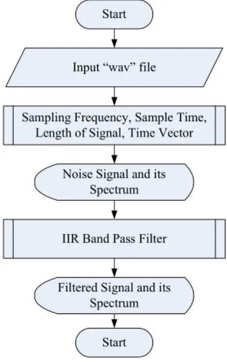
The overall flowchart is shown in Figure 1. The input “wav” file has to be analyzed based on the specified sampling frequency, sample time and length of the signal to response the noise signal and the spectrum of that noise signal can be displayed. And then these signals are passed through to the implemented IIR band pass filter and the noise reduction signal can be acquired. The developed system can be applied in real GSM system. The simulation results are shown in the following figures. In most of the previous studies, the problem of bumblebee noise was addressed by software-related changes. This study addresses the problem by designing band pass filters because if the processing time is miscalculated, software approaches can be ineffective in reducing the bumblebee noise.
Start
Input “wav” file
Sampling Frequency, Sample Time, Length of Signal, Time Vector
Noise Signal and its Spectrum
IIR Band Pass Filter
Filtered Signal and its Spectrum
Start
Figure 1. Overall Flowchart
IV. SIMULATION RESULTS
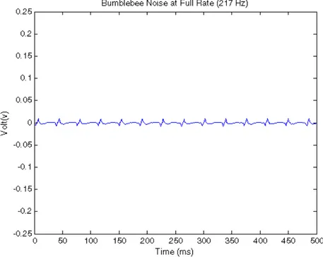
Figure 2. Bumblebee Noise at Full Rate (217KHz)
IJECSE, Volume 3, Number 3
Han Su Kyi et al.
188
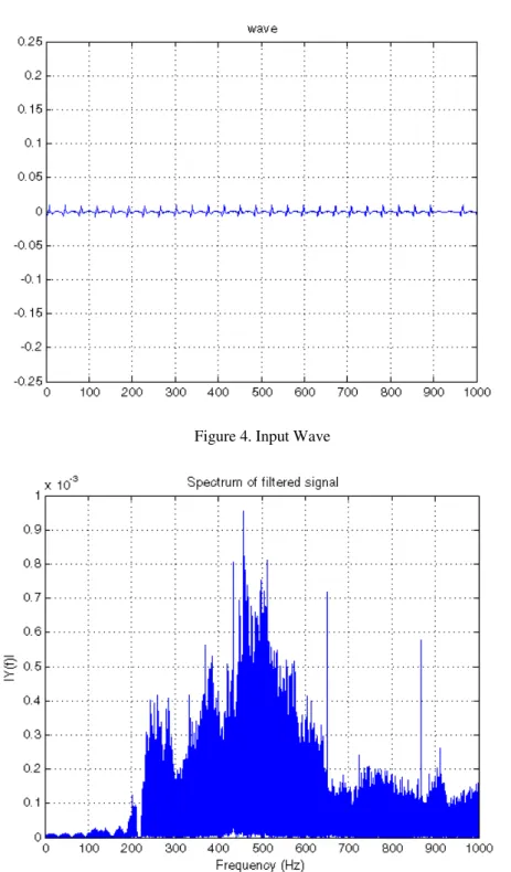
Figure 4. Input Wave
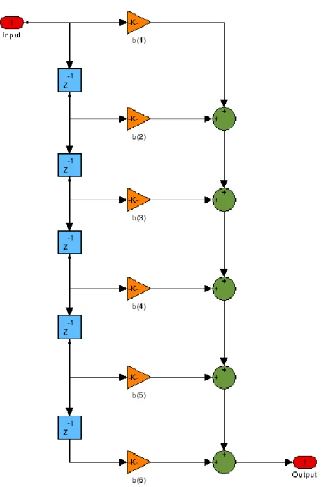
Figure 6. Developed IIR Band Pass Filter Design
Figure 6 shows the developed IIR band pass filter design. This design is constructed under the required specific parameters with the help of MATLAB.
IV.CONCLUSION
IJECSE, Volume 3, Number 3
Han Su Kyi et al.
190
experiments and it was found that, on an average the bumblebee noise was reduced up to specific noise in input signal.
REFERENCE
[1] 3rd Generation Partnership Project; Technical Specification Group GSM/EDGE Radio Access Network; Physical layer on the radio path; General description (Release 1999), 3GPP TS 05.01 V8.9.0, Nov 2004.
[2] Leeds, S. David, “Adaptive noise cancellation of coupled transmitter burst noise in speech signals for wireless handsets,” Acoustics, Speech, and Signal Processing, 2002 IEEE Int. Conf., May 2002. Vol. 4, pp. 3924–3927.
[3] I. Claesson, A. Rossholm, “Notch Filtering of humming GSM mobile telephone noise,” Information, Communications and Signal Processing, 2005 Fifth Int. Conf., Dec. 2005, pp. 1320–1323.
[4] I. Claesson, A. Nilsson, “Cancellation of humming GSM mobile telephone noise,” Information, Communications and Signal Processing, 2003 and the Fourth Pacific Rim Conf. on Multimedia. Proc. 2003 Joint Conference of the Fourth Int. Conf., Dec. 2003, Vol. 1, pp. 114– 118.
[5] Youngbin Chang et al., “Data burst transmission scheme to suppress audible noise in mobile handheld terminal,” Consumer Electronics, 2004 IEEE Int. Symp. Sep. 2004, pp. 178–181.
[6] Es'kov EK, Sapozhnikov AM., “Mechanism of generation and perception of electric fields by honey bees,” Jounal of Biofizika, Russian, Nov. 1976, Vol. 21, pp. 1097–1102.