Effect of working parameters and nozzle wear rate
onto the spray quality in use of different fan flat
nozzle
Wpływ parametrów pracy i zu
ż
ycia rozpylaczy na jako
ść
oprysku z wykorzystaniem ró
ż
nych rozpylaczy
płaskostrumieniowych
Eleonóra KECSKÉSNÉ NAGY1, Milan KOSZEL2* AND István SZTACHÓ-PEKÁRY3
1 Fruit and Vine-Growing Institute of Faculty of Horticulture, Kecskemét College, Hungary
2 Department of Machinery Exploitation and Management of Production Processes, University of Life Sciences in Lublin, Poland, *correspondence [email protected]
3 Machinery, Economy and Rural Development Institute of Faculty of Horticulture, Kecskemét College, Hungary
Abstract
The subject of the analysis was the influence of working parameters (working pressure and working speed) on drop tracks size and changes in flow rate level from flat fan nozzle. New nozzles and nozzles after laboratory wear were tested. The influence of nozzles wear on drop tracks size was examined. It was found that increase in liquid flow rate results in higher values of mean diameter of drop track. Increase in working pressure or working speed cause decrease in drop tracks size and reduce merging of drops on spray surface. Increase in wear degree was followed by increased coverage rate. This phenomenon is especially dangerous when using nozzles with considerable wear degree for agricultural spray since this poses ecological threat to environment.
Keywords: flow rate, nozzles wear, working parameters
Streszczenie
Tematem przedstwionej pracy był wpływ parametrów pracy (ciśnienia roboczego
i prędkości roboczej) na wielkość śladów kropel w funkcji zmian natężenia wypływu
cieczy z rozpylaczy płaskostrumieniowych. Badano rozpylacze nowe i po laboratoryjnym zużyciu. Badano wpływ zużycia rozpylaczy na wielkość śladów
kropel. Stwierdzono, że ze wzrostem natężenia wypływu cieczy wzrasta średnia średnica śladów kropel. Wraz ze wzrostem ciśnienia roboczego lub prędkości
roboczej następuje odpowiednio zmniejszenie śladu kropli oraz ograniczenie
Słowa kluczowe: natężenie wypływu, parametry pracy, zużycie rozpylaczy
Detailed abstract
Chemiczna ochrona roślin jest obecnie podstawową metodą skutecznego i szybkiego
zwalczania agrofagów. W związku z tym dużego znaczenia nabiera umiejętne
stosowanie chemicznych środków ochrony roślin, tj. zachowanie ich skuteczności
i jednocześnie zmniejszenie zagrożenia dla środowiska oraz dla zdrowia ludzi
i zwierząt. Aby zmniejszyć zanieczyszczenia środowiska i koszty produkcji rolniczej
ważne jest stosowanie pestycydów z odpowiednią precyzją. Kiedy rozpylacze są
zużyte, mogą nie dozować krople o odpowiedniej średnicy. Najbardziej
rozpowszechnione badania nad zużyciem rozpylaczy dotyczą zmian natężenia
wypłwyu cieczy (Sawa, et al., 2003).
Konsekwencją zużycia rozpylaczy jest zwiększenie średnicy kropli. Zużyte
rozpylacze produkują krople o większej średnicy, co powoduje zlewanie się kropel
i spływanie z chronionej powierzchni. W konsekwencji następuje zanieczyszczenie środowiska i wód gruntowych (Biziuk, et al., 2001). Jeśli rozpylacze wytwarzają zbyt
małe krople następuje znoszenie ich przez wiatr lub wyparowanie kropli zanim dotrze
ona na powierzchnię oprysku.
Celem badań był wpływ zużycia rozpylaczy na wielkość kropel, średnicęśladu kropli,
stopnia pokrycia opryskanej powierzchni i liczbę kropli.
Przeprowadzone badania potwierdziły wpływ ciśnienia roboczego i prędkości
roboczej na jakość oprysku. Wzrost zużycia rozpylaczy powoduje zwiększenie
natężenia wypływu cieczy, co wpływa na zwiększenie śladu kropli pozostawionego
na opryskanej powierzchni. Wzrost stopnia zużycia rozpylaczy powoduje
zwiększenie stopnia pokrycia. Zależność ta wynika z wytwarzania przez zużyty
rozpylacz kropli, które pozostawiają ślad o większej średnicy. Wzrost prędkości
roboczej powodował zmniejszenie stopnia pokrycia. Liczba śladów kropli malała wraz
ze wzrostem stopnia zużycia rozpylaczy. Zależność ta wynika ze zlewania się kropli.
Wysokie ciśnienie robocze w rozpylaczach z niskim natężeniem wypływu cieczy, jak
również użycie zużytych rozpylaczy powoduje pogorszenie parametrów pracy
rozpylaczy rolniczych, odpowiednio do wzrostu liczby kropel o małej średnicy lub
znoszenia kropel z chronionej uprawy. Mediana objętościowa (Dv50) kropel wytwarzanych przez nowe rozpylacze o takiej samej objętości cieczy, ale
wykonanych z różnych materiałów była w przybliżeniu taka sama. Dv50 kropel generowanych przez nowe rozpylacze powiększyły się niezależnie od materiału
z jakiego wykonany jest rozpylacz. Dv50 kropel generowanych przez zyżyte rozpylacze wzrosła. Dv50 kropel generowanych przez zużyte ropzylacze była ogólnie większa niż generowanych przez nowe rozpylacze.
Introduction
requirements to reduce environmental pollution and costs of agricultural production it is important to use pesticides with appropriate precision.
The quality of spraying machine work is affected by several technological, technical and climatic factors, the most important of which include the type of machine, choice of nozzles, appropriate spray parameters, temperature and humidity as well as adherence to the instructions of plant protection agent producers (Sawa, et al., 2003).
Agricultural spray nozzles are manufactured from a variety of materials including brass, stainless steel, hardened stainless steel, nylon, plastic, and ceramic (Wargocki, 1995)]. Nozzles made from different materials have different wear characteristics due to flow through their tips. Other factors that affect orifice wear include the shape and size of orifice, spraying pressure, usage time, and type of formulation applied.
When nozzles wear, they may no longer produce the desired droplet size. Most known research on nozzle wear has concentrated on the change in flow rate (Friesen, 1984; Menzies, et al.,1976; Novak and Cavaletto, 1988; Pearson and Fry, 1984; Reed and Ferrazza, 1984; Reichard, et al., 1991, Sztachó-Pekáry, 2004) and on spray pattern (Friesen, 1984; Ozkan, et al., 1991; Sztachó-Pekáry, 2006).
The consequence of nozzle wear is an increase in drops mean diameter. Nozzle wear influences merging degree of drops, which causes drops to flow off the surface of protected plants. Consequently, plant protection agents permeate into underground water and contaminate environment (Biziuk, et al., 2001). If nozzles generate very small drops, they are drifted away by wind or the liquid evaporates before falling on protected plants.
The small droplets produced in this process are recognized as major contributor the off-target drift, resulting in environmental contamination, and in addition to this it has a serious food safety risk (Sawa, et al., 2003).
The objective of this study was to investigate the effect of nozzle wear on droplet size, drop track diameter, spray coverage degree and droplet numbers and droplet sites, respectively.
Volumen median diameter (Gajtkowski, 2000) from the following equation is calculate:
(
)
− − + − =∑
∑
∑
− = = = 1 1 1 1 50 5 , 1 j i i j i i j i i v v h v j h VMD , gdzie:h – lenght of class range [µm],
j – class number, which volume participations achieve 50% test volume,
i
Materials and Methods
Laboratory nozzle wear tests were conducted parallel in the Department of Machinery Exploitation and Management of Production Processes, University of Life Sciences in Lublin, Poland and in the Machinery, Economy and Rural Development Institute of Faculty of Horticulture, Kecskemét College, Hungary.
In Lublin the new nozzles (LECHLER ID 120-03) of nominal flow rate 1.17 l.min-1 were destroyed. A testing stand with sprayer boom travel speed of 5 km.h-1, 7 km.h-1, 9 km.h-1 was used for drop placement on model surface. Model surface consisted of film strip of the size 100 x 10 cm. Measurements were recorded at the pressure of 3 bars, 5 bars, 7 bars. Tests were performed with 5 repetitions.
The nozzles were destroyed to reach 5% and 10% wear rates, which were calculated by comparing the change in liquid flow rate from each nozzle to the nominal flow rate. Water solution of kaolin was used for destroying nozzles. 9.8 kg of kaolin was added into 150 liter of water (Ozkan, et al., 1992).
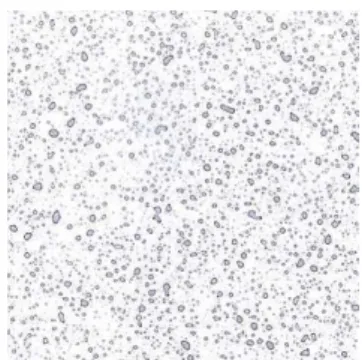
After drying up of drops on the model surface 5 images of the size 5 x 5 cm were scanned from each film strip (Figure 1). The first image was scanned in the nozzle symmetry axis, and then 10 and 20 cm on the left and right sides of such an axis.
Figure 1. Demosntration image of drops on the model surface. Rysunek 1. Przykładowe zdjęcie śladów kropel na powierzchni.
Drop track diameter, spray coverage degree and droplet numbers were calculated using the computer program Image Pro+ (Media Cybernetics).
In Kecskemét new flat spray nozzles (80º fan angle) were selected with nominal flow
Droplet size and droplet pattern distribution test
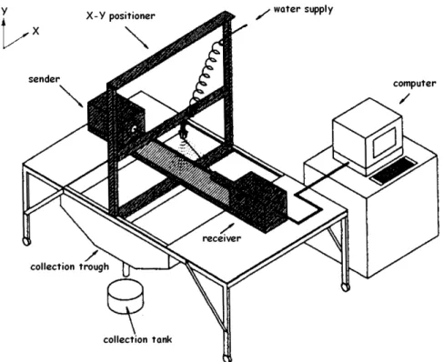
Droplet size spectrums of new and worn nozzles were measured with the system illustrated in Figure 2. This system consists of a MALVERN SPRAYTEC laser-diffraction droplet and particle sizer (Malvern Instruments Inc.),a pumping system, an X–Y positioner, and a computer to perform data collection and analyses. The MALVERN SPRAYTEC instrument can measure droplets ranging in size from 0.5 µm
to 1880 µm with an accuracy of ±4% on the volume median diameter. Additional
details of operation of the MALVERN SPRAYTEC droplet size analyzer are discussed by Sztachó-Pekáry (2009).
Figure 2. Droplet size analysis test stand.
Rysunek 2. Stanowisko do badania wielkości kropli.
The test nozzle was mounted on the horizontal member of the X–Y positioner. One motor (12 V DC) was used to move the nozzle a predetermined distance in the horizontal, perpendicular to the laser plane (X) direction. Movement in the vertical (Y) direction was accomplished manually. A 750 mm focal length lens was used during all the droplet size tests. Can be used for measurements lens measure droplets from 5 µm to 1600 µm diameter.
The nozzle was positioned between the laser transmitter and receiver, and at 50 cm above the laser beam. This is the height recommended by the nozzle manufacturers for applying pesticides with 80º spray angle nozzles. The X and Y coordinates of the
A fine filter was placed inside the nozzle body to insure clean water at the nozzle orifice. A pressure regulator maintained pressure at the nozzle between 1.0 and 5.0 bars by steps 0.5 bar.
Several precautions were taken to eliminate factors that could adversely influence measurements with the MALVERN SPRAYTEC. A tarp was used to partially cover the drop sizer and block ambient light from the laser detector. The tarp also reduced the effect of air currents surrounding the test stand on the spray. To eliminate deposition of small droplets on outer surfaces of the optical lenses of the droplet size analyzer, an air curtain created by a small fan was directed to the front of the beam expander and detector lenses.
After a nozzle was mounted on the X–Y positioner, and the nozzle position established, the laser was turned on and the electronic and the optical backgrounds reading were determined without spray. This is necessary to determine the influence of the ambient light and solid particulates in the air on the measurements. Next the pump was activated and the spray pressure was adjusted to the actual measurement pressure. The droplet size analyzer was activated to take measurements. The computer software allows the droplet size analyzer to make a 0.1 ms snap in each seconds during the measurement. Values from this data were used for the final droplet size analysis at each position. After each measurement, the pump was turned off. Some of the statistics determined at each test location were: Dv10, Dv50, Dv90.This diameters represented droplet size where 10, 50 and 90%, respectively, of the total spray volume is composed of equal or smaller diameter droplets. Tests were performed with 9 repetitions.
After the droplet size tests with all the new nozzles were completed, we determined the spray distribution patterns of new nozzles using a spray pattern analysis system, described in detail by Sztachó-Pekáry (2009). Then, the new nozzles were subjected to a wear process using a test stand that was constructed and used. The test stand consists mainly of a 200 dm3 tank with a pumping system to circulate a mixture of water and kaolin clay (60 g.dm-3) through nozzles. A paddle-type agitator at the bottom of the tank ensured a uniform mixture of water and kaolin during nozzle wear tests. At the completion of this process, the worn nozzles were tested to determine the effects of nozzle wear on both spray deposit and droplet size distributions.
Results
Investigation in Lublin
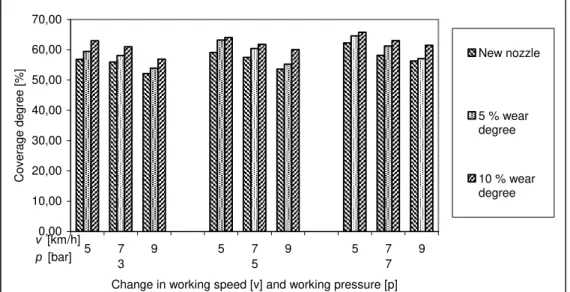
Increase in working pressure results in generating drops with smaller diameter by the nozzle. Consequently, it was found that a rise in coverage degree coincided with increase in working pressure. However, increase in working speed caused decrease in coverage degree (Figure 4).
Figure 5 shows graphic interpretation of the results concerning the number of droplets per 1 cm2 as a function of changes in working pressure and working speed. Excessively low pressure or slow working speed cause merging of droplets. This process is especially dangerous while performing plant protection spray with nozzles with high wear rate.
0,00 100,00 200,00 300,00 400,00 500,00 600,00 700,00
5 7 3
9 5 7
5
9 5 7
7 9
Change in working speed [v] and working pressure [p]
M
ea
n
di
am
et
er
o
f d
ro
p
tr
ac
k [µ
m
]
New nozzle
5 % nozzle wear
10 % nozzle wear
v [km/h]
p [bar]
Figure 3. Change in mean diameter of drop track as a function of changes in working pressure (respectively for new nozzles and 5% and 10% wear rates). LECHLER ID 120-03 nozzle.
Rysunek 3. Zmiana wielkości kropli w funkcji zmian ciśnienia roboczego
(odpowiednio dla rozpylaczy nowych oraz z 5 i 10% stopniem zużycia). Rozpylacze
0,00 10,00 20,00 30,00 40,00 50,00 60,00 70,00 5 7 3
9 5 7
5
9 5 7
7 9
Change in working speed [v] and working pressure [p]
C ov er ag e de gr ee [% ] New nozzle
5 % wear degree
10 % wear degree
v [km/h] p [bar]
Figure 4. Changes in coverage degree as a function of changes in working pressure
(respectively for a new nozzle and 5% and 10% wear rates). LECHLER ID 120-03 nozzle.
Rysunek 4. Zmiana stopnia pokrycia w funkcji zmian ciśnienia roboczego
(odpowiednio dla rozpylaczy nowych oraz z 5 i 10% stopniem zużycia). Rozpylacze
LECHLER ID 120-03.
0 5 10 15 20 25 30 35 5 7
3 9 5 75 9 5 77 9
N o of d ro ps [1 .c m -2]
Change in working speed [v] and working pressure [p]
New nozzle
5 % wear degree
10 % wear degree
v[km/h] p[bar]
Figure 5. Changes in the number of drops per 1 cm2 as a function of changes in working pressure (respectively for a new nozzle and 5% and 10% wear rates). LECHLER ID 120-03 nozzle.
Rysunek 5. Zmiania liczby kropel na 1 cm2 w funkcji zmian ciśnienia roboczego
(odpowiednio dla rozpylaczy nowych oraz z 5 i 10% stopniem zużycia). Rozpylacze
Investigations in Kecskemét Effect of nozzle wear on flow rate
Following is a summary of the effects of orifice wear on flow rates. Detailed results are given by Sztachó-Pekáry (2004).
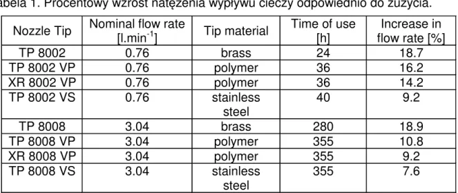
Table 1 shows tip numbers, materials, nominal flow rate, the number of hours the nozzles were subjected to wear tests, and percent flow rate increase at the end of the test. Generally, stainless steel was the most resistant to wear, followed in order of decreasing resistance to wear by polymer and brass. With the ends of the tests, the increase in flow rate with stainless steel tips was always less than polymer tips. For the same material, nozzle tips with lower flow capacities wore much faster than nozzles with higher capacities. For all nozzle capacities, the stainless steel tips had average use times 6.5 and 2.5 times longer than brass and polymer tips, respectively, before flow rates increased 10%. The percent increase in flow rates for all brass, polymer and stainless steel tips varied directly with approximately the square root of time of use.
Table 1. Percent increase of nozzle flow rate due to wear .
Tabela 1. Procentowy wzrost natężenia wypływu cieczy odpowiednio do zużycia.
Nozzle Tip Nominal flow rate [l.min-1] Tip material Time of use [h] flow rate [%] Increase in
TP 8002 0.76 brass 24 18.7 TP 8002 VP 0.76 polymer 36 16.2 XR 8002 VP 0.76 polymer 36 14.2 TP 8002 VS 0.76 stainless
steel 40 9.2 TP 8008 3.04 brass 280 18.9 TP 8008 VP 3.04 polymer 355 10.8 XR 8008 VP 3.04 polymer 355 9.2 TP 8008 VS 3.04 stainless
steel 355 7.6
Effect of nozzle wear on droplet size and spray pattern distribution
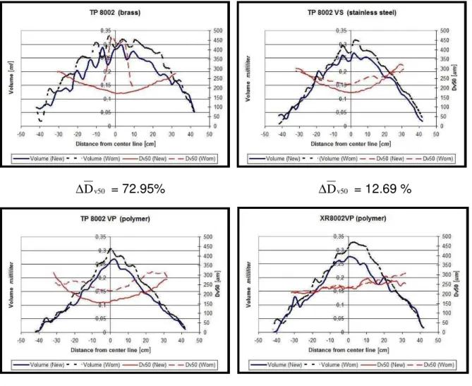
The results of droplet size measurements obtained from new and worn nozzles with nominal flow rates of about 0.8 and 3.0 l.min-1 are shown in Figure 5 and 6, respectively. The data shown in figures indicate the Dv50 values of droplets measured
at 2.5 mm increments along the X-axis. Regardless of nozzle material, the Dv50 of
distributions of 0.8 l.min-1 nozzles were generally smaller at the centers of the patterns for both new and worn nozzles. At -333.75 cm, the Dv50 of the new 0.8 l.min -1 nozzles was about 150-200
µm, and it remained relatively constant within ±20 cm of
the center of the pattern (Figure 6). The Dv50 of distributions of all other new and worn
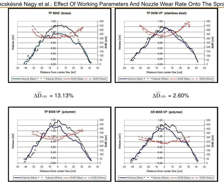
nozzles first decreased away from the centers of the patterns, then began to increase at about ±20 cm away from the center of the pattern as illustrated in Figure 7 for 3.0 l.min-1 nozzles.
while the brass 0.8 l.min-1 nozzle used in our tests had an increase of 18.7% to 18.9% flow rate, the same capacity hardened stainless steel nozzle had only 7.6% flow rate increase. Research needs to be conducted to determine the change in droplet size distributions of nozzles after increase in flow rates reaches certain levels such as 10, 20, 30, 40, and 50% of the original output. Results from such research will help determine if due to wear, changes in droplet size distributions become intolerable requiring replacement of the nozzles.
∆Dv50 = 72.95% ∆Dv50 = 12.69 %
∆Dv50 = 35.01% ∆Dv50 = 6.05%
Figure 6. ∆Dv50 (weighted volume median diameter) distributions of new and worn nozzles with nominal flow rate of 0.8 l.min-1.
∆Dv50 = 13.13% ∆Dv50 = 2.60%
∆Dv50 = 6.93% ∆Dv50 = 7.19%
Figure 7. ∆Dv50 (weighted volume median diameter) distributions of new and worn nozzles with nominal flow rate of 3.0 l.min-1.
Rysunek 7. ∆Dv50 (mediana objętościowa) dla nowych i zużytych rozpylaczy o nominalnym natężeniu wypływu 3.0 l.min-1.
Weighted Mean Droplet Size Distribution
greater portion of volume of liquid in smaller droplets than at the edges of the patterns.
To better understand the overall droplet size distributions across the spray pattern, a weighted volume median diameter, designated as Dv50 was calculated for each new and worn nozzle. This was accomplished by measuring volumes of the liquid sprayed at 2.5 mm intervals across the swath (267 points), and using this data in conjunction with the drop1et size measurements taken at each of these 267 positions. The Dv50 for the entire spray swath was determined from the following equation:
∑
∑
= =
⋅
= n
i i n
i
i i v v
V V D D
1 1
50 50
] ) [(
,
where:
(Dv50)i – volume median diameter at position i [µm], Vi – spray volume at position i [mm],
n – number of test positions.
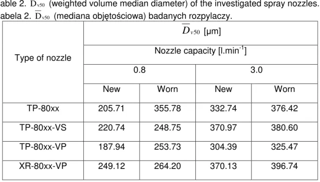
Table 2. Dv50 (weighted volume median diameter) of the investigated spray nozzles. Tabela 2. Dv50 (mediana objętościowa) badanych rozpylaczy.
Type of nozzle
50
v
D
[µm]Nozzle capacity [l.min-1]
0.8 3.0
New Worn New Worn
TP-80xx 205.71 355.78 332.74 376.42
TP-80xx-VS 220.74 248.75 370.97 380.60
TP-80xx-VP 187.94 253.73 304.39 325.47
XR-80xx-VP 249.12 264.20 370.13 396.74
0 50 100 150 200 250 300 350 400
0 0,5 1 1,5 2 2,5 3 3,5
Nominal flow rate, liter/min
W
e
ig
h
te
d
v
o
lu
m
e
m
e
d
ia
n
d
ia
m
e
te
r,
u
m
TP-80xx TP-80xx-VS TP-80xx-VP XR-80xx-VP
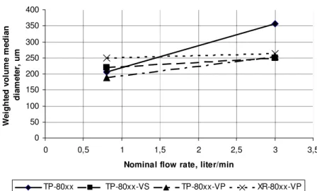
Figure 8. Effect of nominal flow rate on Dv50 (weighted volume median diameter) of new nozzles constructed of different materials and types.
Rysunek 8. Wpływ nominalnego natężenia wypływu cieczy z Dv50 (mediana objętościowa) dla nowych rozpylaczy o różnej konstrukcji i wykonanych z różnego
materiału.
The Dv50 was generally greater for worn than similar new nozzles for all nozzles. The greatest percent increase in Dv50 between new and worn nozzles was 72.95% for the brass nozzles with 0.8 l.min-1 capacity. It is feasible to compare Dv50 of new and worn brass and polymer nozzles, because the percentages of increase in flow rates among the worn nozzles with different capacity nozzles were dose for the brass and polymer nozzles. As indicated in Table 1, the increase in flow rates of brass nozzles due to wear varied from 18.7% to 18.9% (0.8 l.min-1 nominal capacity). Similarly there was a difference of only 9.2% to 7.6% in percent decrease in flow rate due to wear between stainless steel nozzles with different capacities.
Conclusions
The conducted tests confirmed the influence of working pressure and working speed on spray quality. Rise in nozzle wear results in increased flow rate, which causes a larger droplet track left on spray surface and droplet size. Increased nozzle wear results in higher coverage degree. Higher working speed, however, causes decrease in coverage degree. Number of drop tracks decreases with the rise in nozzle wear rate, which is the consequence of merging of drops.
• High working pressure in nozzles with low flow rate as well as using of worn-out nozzles cause deterioration of working parameters of agricultural spray as respectively these increase the number of drops of smaller diameter or make liquid flow off plants surface.
• The Dv50 of droplet size distributions from new nozzles increased as capacities of the nozzles increased, regardless of nozzle material.
• The Dv50 of droplet size distributions from worn nozzles also increased as capacities of the nozzles increased.
• The Dv50 of droplet size distributions was generally greater for worn than similar new nozzles.
References
Biziuk M i in. (2001) Pestycydy. Występowanie, oznaczanie i unieszkodliwianie.
Wydawnictwo Naukowo-Techniczne. Warszawa.
Friesen, O. H., (1984) Evaluation of wear rates of flat spray nozzles. Technical Report. Manitoba Agriculture (August).
Gajtkowski A., (2000) Technika ochrony roślin. Wydawnictwo Akademii Rolniczej.
Poznań.
Ganzelmeier H., (2002) Europäische und internationale Entwicklungen in der Pflanzenschutztechnik. Jahrbuch Agrartechnik; VDMA Landtechnik, VDI-MEG, KTBL; Band 14.
Menzies, D. R., Fisher R. W., Neff A. E., (1976) Wear of hollow cone nozzles by suspensions of wettable powders. Canadian Agricultural Engineering 18 (1). 14 – 15.
Novak, M. J., Cavaletto R. A., (1988) Wear characteristics of flat fan nozzles. ASAE Paper No. 88-1015. St. Joseph, MI: ASAE.
Ozkan H. E., Reichard D. L., Ackerman K. D., (1992) Effect of orifice wear on spray patterns from fan nozzles. Transactions of the ASAE, 35, 4. 1091 – 1096. ISSN 0001-2351.
Ozkan, H. E., Reichard D. L., Sweeney J. S., (1991) Effect of orifice wear on drop size distributions delivered by fan-pattern nozzles. ASAE Paper No. 91-1538. St. Joseph, MI: ASAE.
Pearson, S. L., Fry C., (1984) Wear rates of agricultural spray nozzles. Thirty-sixth Illinois Custom Operators Training School Manual. Urbana, IL: Cooperative Extension Service.
Reed, T. F., Ferrazza J., (1984) Wear life of agricultural nozzles. ASAE Paper No. AA84-00I. St. Joseph, MI: ASAE.
Reichard, D. L., Ozkan H. E., Fox R. D., (1991) Nozzle wear rates and test procedure. Transactions of the ASAE 34(6). 2309 – 2316.
Sawa J., Huyghebaert B., Koszel M. (2003) Parametry pracy opryskiwaczy a jakość
oprysku. Materiały z IV Konferencji: „Racjonalna Technika Ochrony Roślin”.
Sztachó-Pekáry I., (2004) The Effects of Fan Nozzles Orifice Wear on Flow Rate and Spray Patterns. Progress in Agricultural Engineering Sciences, (Budapest) Sample Issue. 7 – 29.
Sztachó-Pekáry I., (2006) Influence of Fan Nozzle Tip Orifice Wear on Spray Pattern Characteristics. Progress in Agricultural Engineering Sciences, (Budapest) Vol 2. No.1. 35 – 49.
Sztachó-Pekáry I., (2009) Új rendszerű cseppméret-elemző berendezés.
Mezőgazdasági Technika(Gödöllő) 50. k. 6. sz. 2 – 4.
Wargocki M., (1995) Ocena trwałości rozpylaczy szczelinowych. Problemy Inżynierii