Journal of Applied Fluid Mechanics, Vol. 9, No. 5, pp. 2257-2266, 2016. Available online at www.jafmonline.net, ISSN 1735-3572, EISSN 1735-3645.
Multi-Dimensional Modeling of the Effects of Air Jet
and Split Injection on Combustion and Emission of
DirectInjection Diesel Engine
M. Mansoury
†, S. Jafarmadar and M. Abdolalipouradl
West Azerbaijan, 57561-15311, Iran
†Corresponding Author Email:[email protected]
(Received August 25, 2015; accepted December 28, 2015)
A
BSTRACTOne of the most important problems in reducing the emissions of diesel engines is to exchange between the oxides of nitrogen and soot emissions. Fuel multiple injection and air injection into combustion chamber are among the most powerful tools to concurrent reduction of these two emissions. In this research, the effect of multiple injection and air injection on combustion and emission parameters has been studied by AVL fire computational fluid dynamic software. Six states of base and modified combustion chamber have been studied in two different injection patterns including 90 (25) 10 and 75 (25) 25 mods. Results show that concurrent applying of both multiple injection and air injection methods has resulted in simultaneous reduction of oxide nitrogen and soot pollutants and a negligible loss is seen in the operational parameters of engine. Compression between six studied cases show that the 90 (25) 10 mode of injection with modified combustion chamber is the optimum mode by decreasing of soot and oxides of nitrogen emissions about 29% and 20% respectively and 6% indicated power loss in compression to the base combustion chamber and single injection mode. The obtained results from the computational fluid dynamic code have been compared with the existing results in the technical literature and show acceptable behavior.
Keywords: Soot; NOx; Indicated power; Air-cell; Split injection; Diesel engines; Combustion chamber.
N
OMENCLATUREATDC after top dead center BTDC before top dead center CFD computational fluid dynamic
Co carbon monoxide
CNC computer numerical control
D soot diameter Mfvfue vapor mass
MS soot mass
° soot mass formation rate ° soot mass oxidation rate
M molecular weight NOx oxide of nitrogen
R gas constant Soot smoke
UHC unburned hydrocarbons
1.
I
NTRODUCTIONDiesel engines are produced due to high efficiency, low specific fuel consumption and relatively high lifetime to be used in vehicles and industrial devices. Heywood (1998) represent that the main pollutants emitted from these engines include smoke (soot) and oxides of nitrogen (NOx), while the (UHC) and (CO) produced by these engines are ignorable. One of the common ways to reduce NOx is reducing the temperature of the combustion chamber. To reduce the smoke, the mixing of fuel and air could also be improved, but there are some limitations for this purpose such as the complexity of the mixing process and
cost of equipment. Patterson et al. (1994) researches show that the improving of fuel and air mixing leads to increasing The temperature of combustion chamber and increases the amount of NOx production. The reduction of one of these emissions would result in increasing of other emission. On the other hand, by codifying new pollution standards, it is necessary that both emissions would be reduced simultaneously so that the engine’s performance parameters are not reduced.
Nehmer and Reitz (1994) has studied the split injection method in order to reduce the combustionNoise and apply fuels with lower Cetanenumber. Schulte et al. (1990) have applied this method in order to reduce the period of ignition delay and control the sudden increasing of pressure inside the cylinder. Osuka et al. (1994) have shown that this injection method reduces the intensity of premixed combustion by reducing the ignition delay period and since mostly nitrogen oxides are produced in this combustion phase, they lead to reduce the amount of this emission. Bianch et al. (2001) has studied the simultaneous reduction of soot and Nox by computational fluid dynamics of KIVA III via split injection method and showed that in this method there is a relationship between reduction of soot pollutant and optimal using of oxygen in combustion chamber. Tatschi et al. (2001) has studied the exhaust gas recirculation and double fuel injection method by commercial computational fluid dynamics software, AVLfire. Their results had a good adaption with the resulting information from experimental researches. Shayler et al. (2004) has studied the effect of sprayed fuel per pulse and injection delay dwell between two pulses over soot and NOx pollutants. Gill et al. (2005) has studied the effect of split injection method on fuel-air mixing and combustion parameters by performing experimental studies in a single-cylinder diesel engine and could provide high quality pictures from injection and combustion in this engine. Jafarmadar (2013) has examined the effect of split fuel injection on the soot and NOx emissions in two direct injection and indirect injection engines. Poorghasem et al. (2012) has studied the split injection method with increasing of injection pressure in order to reduce smoke and oxides of nitrogen and improved the soot oxidation with enhancing of combustion quality by providing suitable mixing of fuel and air. Another efficient method to simultaneous reducing of soot and NOx is injecting air into combustion chamber. Nagano et al. (1991) has decreased the smoke and NOx significantly by creating air jet by air accumulation generator. Choi et al. (1995) has studied the effect of increasing mixing and turbulence on emissions by injecting high pressure gas dioxide carbon and nitrogen into combustion chamber in an experimental setup. The results show that nitrogen injection into chamber leads to optimality of fuel and air mixing and decreasing of smoke oxidation. Mather and Reitz (1995) have presented a scheme in which a secondary chamber has been made inside the piston body and connected to the main combustion chamber by throats, Results showed that by decreasing the air in compression course and by increasing combustion rate in expansion course, the amount of soot and NOx pollutants would be reduced simultaneously. Jafarmadar et al. (2012) has studied the creation of air jet by embedding air cell and insulating the body of combustion chamber in order to avoid the loss of operational parameters by commercial CFD code AVLfire. Due to high cost and time consuming of experimental tests over engine, numerical methods
are suitable solution to eliminate these problems and faster response to the examination and design problems. At the previous researches by authors effect of air injection on emissions, combustion and exergy parameters was studied (2013, 2015). In the present study, two split fuel injection and air injection methods in MT.4.244 engine have been studied. It is necessary to say that Poorghasem et al. (2012) has studied on the effect of fuel split injection on this engine and indicated that two injection patterns of 75(25)25 and 90(25)10 have no significant effect on engine’s performance parameters by concurrent reduction of NOx and soot emission (90 (25) 10 indicates 90 percent of fuel injected in the first pulse, 10 percent in second pulse and 25 crank angle dwell between the two injection pulse). In this research, the effect of air jet due to creating air cell inside the piston body at these two split injection patterns has been studied. In Table (1), the characteristics of engine, injectors and operation condition have been mentioned.
Table 1 Engine specifications and operating conditions
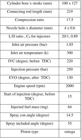
Cylinder bore x stroke (mm) 100 x 127
Connecting rod length (mm) 219
Compression ratio 17.5
Nozzle hole x diameter (mm) 4 x 0.6
L/D ratio , Cd for injectors 20/1, 0.89
Inlet air pressure (bar) 1.85
Inlet air temperature (k) 300
IVC (degree, before TDC) 220
Injection pressure (bar) 250
EVO (degree, after TDC) 130
Engine speed (rpm) 2000
Start of injection (degree, before
TDC) 15
Injected fuel mass (mg) 64
Spray con angle (degree) 14.5
Spray included angle (degree) 55
Piston type omega
2.
P
REPARATIONA
IR-C
ELLI
NSIDET
HEP
ISTONchamber, Fig.2 (b). in last phase filled the initially hole that created in first step by using of cap and Argon-gas welding, Fig.2 (c). modified piston is demonstrated from top view inFig. 3.
Fig. 1. cross section view from Modified piston.
Fig. 2. (a) hole drilled in bottom of piston.
Fig. 2. (b) Creating throats form piston bowl to air-cell.
Fig. 2. (c) filled air-cell by argon gas welding.
Fig. 3. Modified piston from top view
.
E
XPERIMENTAL SETUPFig.4 shows the test room. A hydraulic dynamotor,
which was directly connected to the motor shaft, was used to measure the performance parameters. A gas analyzer system was used to measure NOx by NDIR (non-dispersive infrared gas analyses).Smoke measured using an AVL415Ssmoke meter. The inlet airflow is filtered and then is measured by a flow meter. An accuracy sensor measures the fuel consumption rate like the inlet airflow. A piezoelectric type pressure transducer mode is reporting the instantaneous pressure by sampling the inner pressure of the combustion chamber. In this engine, the transducer is adjusted so that the combustion chamber pressure is reported for every 0.1 of the crank angle. The particles matter are determined before and after sampling by measuring the weight of the filter installed on the way of the exhaust gases. In order to increase the experiment accuracy and reduce the probable error in results, all the analyzer equipment of the outlet produced are calibrated before and after each test .the emission measurement is repeated 5 times in each experiment and finally the average of the results is used. The instruments that used in this process is listed in Table (2).
Fig. 4. Test instrument.
Table 2 Test instrument
Pressure sensors GU22C
NOX analyser AVLDICOM
Smoke meter AVLsmoke meter
Fig. 6. Grid dependency based on the in-Cylinder pressure.
Fig. 7. Comparison of predicted and measured Cylinder pressure.
3.
C
OMPUTATIONALM
ODELFor the 3-D simulation, firstly engine cylinder is modeled by Solid work software. Next, complicated simulation of engine and creating moving mesh is carried out by means of Fame Engine Plus tool in commercial CFD code AVL Fire. Regarding that the analysis is done on the closing cycle, from intake valve closure (140 BTDC) to exhaust valve opening (130 ATDC), so the domain of the calculation include the space of cylinder, which is divided into head, liner and piston bowl. Simulation of modified engine condition follows the above-mentioned process. In this condition, an air cell and four throats are added to the initial geometry. The diameter of the air cell is 35 mm and its height is 1.34 mm. The diameter of the each throat is 1 mm. Fig.5demonstrates the simulated combustion chamber in base and modified conditions. Inlet temperature at 300 K, initial pressure at 1.85 bar, and engine speed at 2000 rpm are set to be. In-cylinder swirl for both base and modified cases are considered to be uniform, the amount of exhaust Gas recirculation is assumed to be zero. AVL Fire software, similar to other CFD software operating according to infinitive volume method, carries out the discretization of equations of mass continuity, momentum and energy as well as the turbulence model, and then by utilizing an iteration algorithm, solves the equations. this model has employed Shell auto-ignition model offered by Halstead (1997), Eddy breakup combustion model that presented by Patterson (1994), the model that applied for transferring heat and evaporation of the fuel droplets represent by Dukowicz (1998).In order to investigate grid dependency, combustion chamber pressure at 100% load condition for 22504 cells and 56321 cells is presented in Fig.6. As can be seen in
the figure, increasing or decreasing number of the cells has no effect on the results. It is seen that there is a good agreement between the obtained and experimental results. It should be mentioned that the peak pressure discrepancy between the computational and experimental models for modified piston is less than 2% in Fig.7.
40˚ BTDC
20˚ BTDC
0˚ TDC
25˚ ATDC
40˚ ATDC
60˚ ATDC
Fig.8 indicates speed vectors of modified chamber at various cranks Angles obtained from AVL fire.In compression stroke the amount of air is embedded in air-cell and in explosion stroke, stored air is returned into the main chamber.
The obtained peak speed at angle 360 CA toward secondary chamber is 126 m/s.By fuel injection and start of combustion after top dead center, the speed of airflow at the throat reduces and at angle about 365 CA reduces to zero. Then, the flow direction changes toward main chamber.
Inlet airflow into the main combustion chamber through air cell causes to increase of amount of fresh air and oxygen molecules in diffusion combustion period and the remaining of fuel at the end of combustionphasehas better oxidation with the excess oxygen, as well as due to increasing of combustion intensify,producedParticulate matter atExpansion stroke is reduced.
4. IN CYLINDER PRESSURE
Fig. 9-11 show the pressure of combustion chamber for single injection, 75 (25) 25 and 90 (25) 10 modes in base and modified case. The value of peak pressure has been reduced slightly in the modified case with single injection over the original state of single injection. The reason of this fact is the reduction of available air to create proper mixture of fuel and air in the premixed combustion step. In split injection, due to this fact that the fuel injection is done near top dead center in this engine, the relative loss of pressure occurs over pressure diagram near TDC after the first peak, this is due to the delay in fuel injection and increasing ignition delay. little amount of fuel is combusted as premixed condition and releases some energy where the relative loss of pressure occurs by continuous movement of piston toward bottom dead center in expansion step, but in the following, the pressure is increased by increasing the heat release rate. The sensible effect of this process is seen in the second peak of pressure curve. In the modified state of engine accompanied with fuel split injection by recessing air from the second chamber into the main combustion chamber, more amount of air is provided to better mixture with the injected fuel in the second pulse of injection. The stored air in the air-cell enters into the main combustion chamber in jet form and by amplifying turbulence intensifies; provide more oxygen to burning of injected fuel at the final phase of injection.
On the other hand, the temperature of the main chamber has been increased due to releasedenergyBy burning the injected fuel at the first combustion pulse and the molecules of injected fuel entered into an environment with higher temperature and lead to the secondary mixture of fuel and air are burnt with faster rate at diffusion combustion period.
5.
T
EMPERATUREO
FC
OMBUSTIONC
HAMBERFigs.12-14 represent the temperature of combustion
chamber at six studied cases. Returning the air jet at the end of pre mixed combustion process into the main chamber in the modified case has led to increasing of released heat at diffusion combustion phase and temperature is increased in this phase over the base combustion chamber.
Fig. 9. Mean in-cylinder pressure as a function Of crank angle.
Fig. 10. Mean in-cylinder pressure as a function Of crank angle in 75(25)25 injection mode.
Fig. 11. Mean in-cylinder pressure as a function Of crank angle in 9(25)10 injection mode.
note that the peak temperature of combustion chamber has higher value due to the existence of more air in the base condition over the modified condition. As can be seen in temperatures contours in Fig.24 at expansion stroke, temperature of stored air at air-cell lower than temperature of combustion products in main combustion chamber, therefore when stored air returned from air-cell to main combustion chamber (due to difference of pressure between air-cell and main combustion chamber) temperature of ambient combusted gas at late of expansion stroke is decreased but mean pressure of combustion chamber by enhanced of turbulence due to returned air jet in main combustion is increased.
Fig. 12. In-cylinder temperature as a Function of crank angle.
Fig. 13. In cylinder temperature as a function Of crank angle in 75(25)25 injection mode.
Fig. 14. In cylinder temperature as a function Of crank angle in 90(25)10 injection mode.
Fig. 15. Heat release rate as a function of crank Angle.
Fig. 16. Heat release rate as a function Of crank angle in 75(25)25 injection mode.
Fig. 17. Heat release rate as a function Of crank angle in 90(25)10 injection mode.
Fig. 19. Soot emission as a function of crank Angle in 75(25)25 injection mode
.
Fig. 20. Soot emission as a function of crank Angle in 90(25)10 injection mode
.
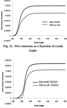
Fig. 21. NOx emission as a function of crank Angle
.
Fig. 22. NOx emission as a function of crank Angle in 75(25)25 injection mode
.
Table 3 Soot, NOx and indicated power value For six studied cases
Case
Soot (mg/ lit)
NOx (ppm)
I ndicat ed power
(Kw)
Base chamber 0.93 1500 21.38
Base chamber and 75 (25) 25 injection
mode
0.81 1410 19.73
Base chamber and 90 (25) 10 injection
mode
0.73 1350 20.32
Modified chamber
0.85 1250 21.09
Modified chamber and 75 (25) 25
injection mode 0.80 1150 19.32
Modified chamber and 90 (25) 10 injection mode
0.66 1200 19.81
6.
H
EATR
ELEASER
ATEAccording to the heat release rate diagrams in Figs.15-17, the amount of heat release rate is dropped slightly due to the reduction of available air in premixed combustion step within modified engine at single injection state in comparison to the base engine. At diffusion combustion step, the combustion rate is intensified due to creating air jet from the secondary cell towards the main combustion chamber. At split injection, 75(25)25 and 90(25)10 injection mode in the base and modified engine, the peak of heat release rate which is in the premixed combustion phase has been decreased as a result of reducing the injected fuel, the mixing of fuel and air got out of its optimal state. At diffusion combustion phase in split injection for the base engine, some fuel is injected at the second injection pulse into combustion chamber and due to highness of combustion chamber’s temperature, the injected fuel has combined and combusted with the remained air. At split injection state with the modified piston in diffusion combustion step, the air jet has entered the combustion chamber earlier than the fuel jet related to the second pulse and provided more turbulence in flow field in comparison to base condition.
Temperature contours
Equivalence ratio contours
Soot
Soot contours
Fig. 23. Temperature(k), Equivalence ratio, NOx mass fraction, soot mass fraction Contour Plots
at 410CA forbase and modified model in 90(25)10 injection mode.
7.
S
OOTHiroyasu and Nagle-Strickland-constable offered the models were used for soot formation and oxidation (1962, 2008) this model predicts the production of soot mass MS, by competition
between the soot mass formation rate, ° and the soot mass oxidation rate, ° according to;
= ° ° (1)
The Arrhenius formation rate is proportional to the fuel vapor mass,Mfv , as given by;
° = °.Mfv (2)
Where °is a function of pressure and temperature according to;
°= . . (3)
Nagle-Strickland-constable model is the Arrhenius oxidation rate is proportional to the soot mass;
° = .MS (4)
And oxidation coefficient is function of molecular weight,M , soot mass, MS , soot diameter, D ,
soot density , ρ , and gas constant, R ;
=
. .MS . (5) Figs.18-19 show the soot emissions diagrams. At the single injection state in the base case, Haynes et al (1981) show that the formation of soot has begun from the onset of combustion and up to maximum of diffusion phase is faster than its oxidation rate due to existence of rich fuel regions. The amount of output soot has been decreased over the base engine due to the increasing of fuel and air mixing and also increasing the rate of oxidation at diffusion combustion phase in the modified engine which is caused by injecting air jet into the combustion chamber by air cell at the expansion stroke. At split injection state in the modified engine, more air has been provided at diffusion combustion state, this fact leads to better soot oxidation in comparison to base chamber, and the net value of this pollutant is decreased at the end of combustion.
8. Nox
NOx formation is modeled by the extended mechanism that present by Zeldovich in(1947):
+ ↔ + (6)
N + O ↔ NO + O (7)
global reaction as follows;
+ ↔ 2 (9) By this reaction can be achieved to the NO concentration variation according to time [1];
[
= 2 [ = 2 [ / O2] (10)
The reaction rate Kfis given as;
K =√Aexp E (11)
Dickey et al(1998)demonstrated that high amount of NOx is formed at the premixed combustion phase due to high temperature of combustion chamber [24]. Applying an air- cell leads to lack of available air at the premixed combustion step and the intensity of heat release has been decreased in this step and the amount of NOx is reduced by reduction of combustion chamber’s temperature. The effect of this phenomenon is observable in both states of single and split injections within the modified engine in comparison with the base engine Figs. 21-23 represent the produced NOx emission at Six studied cases.
Table (3) represents the NOx , soot emissions and indicated power value of single and split injection for the base and modified cases of combustion chamber. IN Fig.24, the comparison of temperature, equivalence ratio, NOx and soot counters has been shown in injection mode of 90(25)10 for two base and modified combustion chamber in a plane passed from the Dupree central axis at 410°CA injection angle. It is worth to note that 410°CA is related to a time when the second pulse of injection has started to inject for mode 90(25)10.At split injection in the modified state, the fuel is injected into a region with lower equivalence ratio and temperature over primary state. As it can be seen in the modified state at the tip of spray over the base state, less fuel rich regions have been formed. Generally, those regions with equivalence ratio less than 1and temperature higher than 1800 K are considered as prone regions to form NOx and in regions with equivalence ratio higher than 3 and temperature between 1500 K and 1800 K are considered as prone regions to form soot.
9.
C
ONCLUDINGR
EMARKSIn the present research, the concurrent effect of split injection and air jet injection on combustion and pollution parameters of a direct injection engine in full load state with AVL Fire fluids dynamic code has been studied.For this purpose, two split injection schemes of 75(25)75 and 95(25)10 have been studied for both base and modified engine accompanied with air jet injection where the obtained results are as following:
a. By increasing of the dead volume in base combustion chamber, equal to air-cell and four throats volume in the modified combustion chamber, compression ratio is same in both cases. The volume of air-cell and throats is 6 percent of the base combustion chamber
volume.
b. In split injection, the amount of NOx emission is decreased over single injection state due to dropping of heat release rate peak and retarding in the second injection. Applying an air cell leads to reduction of available air to form a suitable mixing and it reduces the amount of NOx emission by reducing the intensity of premixed combustion. The amount of NOx emission in single injection at modified combustion chamber is reduced 16% in respect to base combustion chamber and in 75 (25) 25 and 90 (25) 25 mods of split injection, amount of this emission is reduced about 18% and 11% with compression to these mode of injection at base combustion chamber.
c. In split injection, the injective fuel enters into a region with high temperature and diluted fuel at the second injection pulse, so less soot emission is formed and creating an air-cell inside the piston body lead to the soot oxidation rate is increased by providing sufficient oxygen for soot oxidation at the final step of combustion. The amount of this emission in single, 75 (25) 25 and 90 (25) 10 mods of injection at modified combustion chamber is decreased about 8%, 10% and 9% respectively.
d. The amount of indicated power at modified combustion chamber in single, 75 (25) 25 and 90 (25) 25 injection mods is negligibly decreased about 1.3%, 2% and 2.5% with compression to base combustion chamber in similar injection mode.
e. The obtained results from AVL Fire 2008 computational code have well agreement with the experimental results in the single injection state in the base engine.
R
EFERENCESBianchi, G. M., P. Pelloni, F. E.Corcione and F. Luppino (2001). Numerical analysis of passenger car HSDI diesel engines with the 2nd generation of common rail injection systems: the effect of multiple injections on emissions (No. 2001-01-1068). SAE Technical Paper.
CFD AVL fire Software, help of CFD AVL fire Software, Part: Spray, 2008.
Choi, C. Y. and D. E. Foster (1995). In cylinder augmented mixing through controlled gaseous jet injection (No. 952358). SAE Technical Paper.
Dickey, D. W., T. W.Ryan and A. C.Matheaus (1998). NOx control in heavy-duty diesel engines-what is the limit? (No. 980174). SAE Technical Paper.
Gill, K., C. Marriner, K. Sison and H. Zhao (2005). In-Cylinder Studies of Multiple Diesel Fuel Injection in a Single Cylinder Optical Engine (No. 2005-01-0915). SAE Technical Paper.
Halstead, M. P., L. J.Kirsch and C. P.Quinn (1977). The autoignition of hydrocarbon fuels at high temperatures and pressures—fitting of a mathematical model. Combustion and flame 30, 45-60.
Haynes, B. S. and H. G. Wagner (1981). Soot formation. Progress in Energy and Combustion Science 7(4), 229-273.
Heywood, J. B. (1998). Internal Combustion Engine Fundamentals, 2nd edition Mc Graw-Hill, Inc.,
New York.
Jafarmadar, S. (2013). The Effect of Split Injection on the Combustion and Emissions in DI and IDI Diesel Engines, Diesel Engine - Combustion, Emissions and Condition Monitoring InTech.
Jafarmadar, S., R. Barzegar, M. Hoseinzadeh and S. Khalilarya (2011). Paper: A numerical investigation of the effect of creating an air-cell and insulting the piston oncombustion process and emission formation in DI diesel engine.Fuel and combustion 3(2), 17-30
Jafarmadar, S. and M. Mansoury (2015). Exergy analysis of air injection at various loads in a natural aspirated direct injection diesel engine using multidimensional model. Fuel 154, 123-131.
Mansoury, M. and S. Jafarmadar (2013). Experimental Investigation of the Effects of Air Injection and Injection Timing in a Natural Aspirated DI Diesel Engine. International Journal of Engineering (1025-2495) 26.12
Mansoury, M., S.Jafarmadar and N. Kousheshi (2015). Experimental Study of the effects of air-injection, injection timing and cooled EGR on the combustion, emissions and performance of a nature aspirated direct injection diesel engine IJST, Transactions of Mechanical Engineering 39, 147,52.
Mansoury, M., S. Jafarmadar, S. M. Lashkarpour and M.Talei (2015). Effect of air jet at the various rate of fuel injection in a direct injection diesel engine. Iranian Journal of Science and Technology Transactions of Mechanical Engineering 39, 219-231.
Mather, D. K. and R. D. Reitz (1995). Modeling the use of air-injection for emissions reduction in a direct-injected diesel engine (No. 952359).
SAE Technical Paper.
Nagano, S., H. Kawazoe and K. Ohsawa (1991). Reduction of soot emission by air-jet turbulence in a DI diesel engine (No. 912353). SAE Technical Paper.
Nagle, J. and R. F. Strickland-Constable (1962). Oxidation of Carbon between 1000-2000 C. In Proceedings of the fifth carbon conference 1(1), 154. New York: Pergamon.
Nehmer, D. A. and R. D. Reitz (1994). Measurement of the effect of injection rate and split injections on diesel engine soot and NOx emissions (No. 940668). SAE Technical Paper.
Osuka, I., M. Nishimura, Y.Tanaka and M. Miyaki (1994). Benefits of new fuel injection system technology on cold startability of diesel engines-improvement of cold startability and white smoke reduction by means of multi injection with common rail fuel system (ECD-U2) (No. 940586). SAE Technical Paper.
Patterson, M. A., S. C. Kong, G. J. Hampson and R. D.Reitz (1994).Modeling the effects of fuel injection characteristics on diesel engine soot and NOxemissions (No. 940523). SAE Technical Paper.
Poorghasemi, K., F. Ommi, H. Yaghmaei and A. Namaki (2012). An investigation on effect of high pressure post injection on soot and NO emissions in a DI diesel engine. Journal of mechanical science and technology 26(1), 269-281.
Schulte, H., M. Duernholz and K. Wuebbeke. (1990). The contribution of the fuel injection system to meeting future demands on truck diesel engines. No. 900822. SAE Technical Paper,
Shayler, P. J. and H. K. Ng (2004). Simulation studies of the effect of fuel injection pattern on NO and soot formation in diesel engines (No. 2004-01-0116). SAE Technical Paper
Tatschl, R., H. P. Gabriel and P. Priesching (2001). FIRE–A Generic CFD Platform for DI Diesel Engine Mixture Formation and Combustion Simulation. In International Multidimensional Modeling User’s Group Meeting at the SAE Congress, Detroit, Mich., USA.