REAL TIME FUEL INJECTION IN SI
ENGINE USING ELECTRONIC
INSTRUMENTATION
V. VINOTH KUMAR, M.E,
Assistant Professor of Mechanical Engineering, Annamalai University. Tamilnadu, India.
ABSTRACT
To meet the present stringent emission norms. These systems are generally termed as Electronic Fuel Injection (EFI) systems. The fuel is injected into the throttle body or into the inlet manifold through an electronic fuel injector, which is controlled by an Electronic Control Unit (ECU). The quantity of fuel injected by the injector plays a vital role as far as performance and emission characteristics of spark ignition engines are concerned. This paper deals with the static and dynamic fuel injection characteristics of two gasoline fuel injectors. The effect of different injection parameters like fuel injection pressure, injection duration, supply voltage to injector and engine speed on the quantity of fuel injected have been studied for two injectors. The injection dead time and its variation with respect to fuel pressure and supply voltage to injector have been analyzed. Based on the analysis of results, an empirical formula has been obtained to determine the dynamic fuel injection quantity from the static fuel injection characteristics and it was compared with the measured values. It is found that the empirical formula developed in this work gives reasonably good results and therefore, it can be used with confidence for predicting the dynamic characteristics of any given injector from its static injection characteristics.
Key words: Emission, electronic injection, SI engine, fuel efficiency INTRODUCTION
Design of SI engines is characterized by homogeneous mixture and spark ignition. The homogeneous mixture is formed outside the engine cylinder and the combustion is initiated inside the cylinder at a particular time towards the end of the compression stroke. The process of mixing is done in the carburetor and is extremely important in spark ignition engines. Till today even though the carbureted fuel system is widely used in spark ignition engines, it has the following drawbacks:
1. High amount of pollutants like UBHC, CO and NOx due to improper vaporization of fuel and incomplete combustion.
2. Difficulty in accurate metering of fuel.
3. Non-uniform mixture distribution to each cylinder in multi-cylinder engines. 4. Low volumetric efficiency due to restricted fuel flow.
In order to overcome the drawbacks of the carbureted fuel system and to meet the present stringent emission standards, there is a need for an alternate gasoline fuel supply system for spark ignition engines. Some of the recent automotive engines are equipped with the gasoline injection system, instead of a carbureted system for the following reasons:
1. Uniform distribution of fuel in multi-cylinder engine. 2. Improved volumetric efficiency.
CARBUREATION SYSTEM OF SPARK IGNITION ENGINE MIXTURE PREPARATION A ND REQUIREMETS
Mixture requirements are different for idling, low, medium, and high load operations. At idling condition a rich mixture is required to obtain adequate combustion stability. This is due to the internal charge dilution of fresh mixture with residual gasses and poor mixing conditions. At part load operating conditions, for good fuel economy, it is advantageous to use a lean mixture. We can dilute the fuel air mixture either with excess air or with recycled exhaust gas.
This dilution improves the fuel conservation efficiency for three reasons:
(1) The expansions stroke work for a given expansion ratio increases as a result of change in thermodynamic properties of the burned gasses;
(2) For a given mean effective pressure, the intake pressure increases with increasing dilution, so pumping work decreases;
(3) The heat losses to the walls are reduced because the burned gas temperatures are low. In the absence of strict engine NOx emission requirements. excess air is the obvious diluents, and at part throttle, engines have traditionally operated lean.
When tight control of NOx, HC, CO emission is required, operation of engines with a stoichiometeric mixture is advantageous so that a three-way catalytic converter can be used to clean up the exhaust. The appropriate diluents is then recycled exhaust gasses which significantly reduces NOx emissions from the engine itself. As load increases charge dilution with residual gasses decreases and mixture conditions are improved. Increasing the amount of air slows down the combustion process which gives rise to large cycle variations. At full load conditions maximum power is the main issue so the mixture required is slightly rich.
ELECTRONIC FUEL INJECTION (EFI) – OVERVIEW
Electronics has emerged as the necessary science to achieve the art of communication, computation and precision. It is only natural that this all parading science should have influenced the automobile. Many accessories, which were mechanically or electrically operated or controlled, have become electronics. Many provisions, which could not be achieved by mechanical or electrical means or electrical means, have become possible because of electronics. Automobile engineers and electronics engineers have joined together to understand the requirements and evolve solutions.
In the case of carburetor, the entire working depends on the throttle position and all the systems must be tailored so that proper mixture delivery takes place at every throttle position. The fuel delivered cannot easily be adjusted to suit certain important operating conditions of the engine such as water temperature, oil temperature and air temperature etc., to the levels of precision called for with stringent emission control requirements. In the case of fuel injection, this is achieved by means of electronics. It is possible to make the system to recognize and respond to every operating condition of the engine and to deliver the required mixture at all operating conditions. With the increases in demands of precision of air fuel ratio control, electronic fuel injection is resorted to. Today EFI system is universally employed to achieve the desired objective. Relative to carbureted fuel systems, the main mechanisms by which an EFI system has helped to reduce exhaust emissions are as follows:
Reduced wall wetting Improved fuel atomization
Greater flexibility in A/F control, which in turn has facilitated
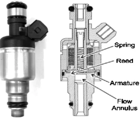
Figure 1. Electronic Fuel Injector
PRESENT WORK
Though MPFI systems are in wide use, they are manufactured by a few companies and supplied to engine manufacturers. Unlike the carburetor these systems cannot be opened and studied under different operating conditions to determine their characteristics and how they influence the performance of an engine. They can be used as black boxes and work only at specified modes as determined by their electronic control unit (ECU). In the laboratory it often becomes necessary to study parameters like injection duration, injection timing etc to ascertain their effects. In such cases the electronic controller has to be redesigned so that these variations can be obtained of engine operating conditions. Thus in such cases the ECU supplied with the injection system cannot be used. The ECU has to be replaced by a flexible control unit.
In this work a fuel injection test bench setup was fabricated which consists of fuel tank, in – tank electric fuel pump, electromagnetic fuel injector, electronic control circuit, injection chamber, and pulse generator. This test bench can be used as a dedicated system for calibrating the given fuel injector under various operating conditions.
EXPERIMENTAL SETUP TEST BENCH SETUP
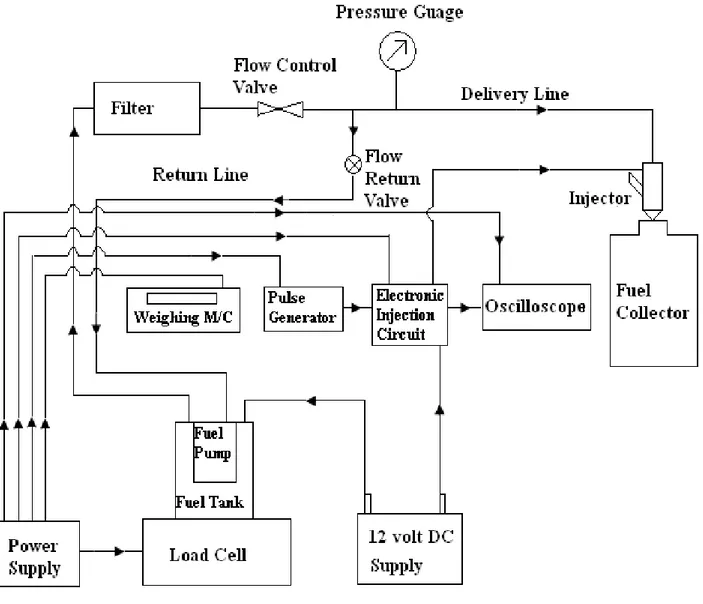
Figure shows the schematic layout of the test bench setup for the injector test, which consists of fuel tank, in-tank electric fuel pump, electronic fuel injector, electronic control circuit, injection chamber and pulse generator. In the injection test, the amount of fuel injected, is determined by measuring the injected fuel quantity at different fuel pressures, injection durations and different speeds. During the test, the fuel pressure was varied from 0.5 to 5 bar in steps of 0.5 bar, injection duration was varied from 2 to 20 ms in steps of 2 ms. and different speeds of 750 rpm, 1500 rpm and 3000 rpm.
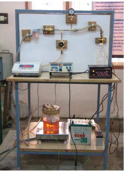
Figure 2. Experimental Setup
Figure 3. Test Bench Layout
RESULTS AND DISCUSSION
The dynamic fuel injection quantity of the injector is influenced by engine speed, fuel pressure, injection duration, injector supply voltage and injection dead time. The amount of fuel injected is obtained by measuring the quantity of fuel injected for a period of 60 seconds at different fuel pressure (0.55 bar to 5 bar), different injection duration (2 msec to 20 msec) and different speeds (750, 1500 and 3000 rpm).
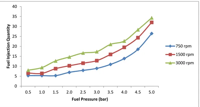
8.1 Effect of Engine Speed
Figure 4. Variation of fuel injection rate at 2.5 bar pressure with various injection uration.
Effect of Fuel Pressure
This test was conducted by varying fuel pressure from 0.5 to 5 bar at different injection durations and constant injector supply voltage of 12 volt DC. Figure 8.2 (a, b, c) shows the effect of fuel pressure on the dynamic fuel injection quantity at different injection durations. As the fuel p r e s s u r e increases, the fuel velocity through the orifices increases, which leads to increase the fuel injection quantity. The fuel injection quantity increases non-linearly with the fuel pressure. The slope of the curve is low at low injection durations but increases with the increase in injection duration due to the effect of injection dead time.
Figure 5. Variation of fuel injection quantity with various pressures at different injection duration at 750 rpm.
0 5 10 15 20 25 30 35 40
0.5 1.0 1.5 2.0 2.5 3.0 3.5 4.0 4.5 5.0
Fuel Injection Quantity
Fuel Pressure (bar)
750 rpm 1500 rpm 3000 rpm
0 5 10 15 20 25 30 35 40 45 50
0.5 1.0 1.5 2.0 2.5 3.0 3.5 4.0 4.5 5.0
Fuel Injection Quantity
Fuel Pressure (bar)
EFFECT OF INJECTION DURATION (750 rpm)
2 m.sec 4 m.sec 6 m.sec 8 m.sec 10 m.sec 12 m.sec 14 m.sec 16 m.sec 18 m. sec
Figure. 6 variation of fuel injection quantity with various pressure at different injection duration at 1500 rpm.
Figure 6. Variation of fuel injection quantity with various pressure at different injection duration at 3000 rpm.
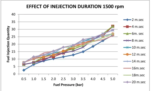
Effect of Injection Duration
The injection duration was increased from 2 to 20 ms at different fuel pressures from 2 to 5 bar and the injector supply voltage was maintained at constant 12 volt DC. The injection duration can’t be reduced below 2 msec as the injection dead time of the injector is 1.4 msec and the orifice of the electromagnetic injector does not operate below 1.4 msec. Injection duration on the dynamic fuel injection quantity is shown in Fig. 8.3 (a,b,c) From the Figure, It was observed that the dynamic fuel injection quantity increases with the injection duration linearly, obviously the high injection duration increases the needle opening time, which increases the fuel injection quantity.
0 5 10 15 20 25 30 35 40
0.5 1.0 1.5 2.0 2.5 3.0 3.5 4.0 4.5 5.0
Fuel Injection Quantity
Fuel Pressure (bar)
EFFECT OF INEJECTION DURATION 1500 rpm
2 m.sec 4 m.sec 6m. sec 8 m.sec 10 m.sec 12 m.sec 14 m.sec 16m.sec 18m.sec 20 m.sec 0 5 10 15 20 25 30 35
0.5 1.0 1.5 2.0 2.5 3.0 3.5 4.0 4.5 5.0
Fuel Injection Quantity
Fuel Pressure (bar)
EFFECT OF INJECTION DURATION 3000 rpm
Figure. 8. Variation of fuel injection quantity with various injection duration at an injection pressures at 750 rpm.
CONCLUSION
There are several reason like complete combustion of fuel due to uniform distribution and accurate metering of fuel, less pollution and improved performance, to use present electronic fuel injection system, as an alternate fuel supply system in modern passenger cars, even though it is having some drawbacks. The main objective of the system is to reduce pollution in order to meet the present stringent emission standards. The injection characteristics of an injector have been studied electronic fuel injection using test bench setup. There many factors that influence the injector performance. These factors are fuel pressure, injection duration, injector supply voltage, and engine speed and injection dead time. This study of injection characteristics of electronic fuel injector will be very much useful for controlling the fuel injection process using the microprocessor and for researches in the performance and emission control of fuel injected spark ignition engines. Also, it will be useful for developing electronic control unit for port fuel injection and gasoline direct injection engines.
• In this work, the effect of fuel pressure, injection duration, engine speed on injection characteristics for single-hole injector has been studied experimentally.
• It was observed that the fuel injection quantity increases non-linearly with the fuel pressure, speed and linearly with the injection duration.
REFERENCES
[1] Bhandari, K et al. (2005): Performance and emissions of natural gas fueled internal combustion engine, A review, JSIR Volume 64; 333-338
[2] Doughty, G E et al. (1992): Natural gas fuelling of a caterpillar 3406 diesel engine. ASME J Engg gas turbine and power. [3] Guowei, L et al. (1999): Optimization study of pilot-ignited natural gas direct-injection in diesel engines, SAE
[4] John Beck. N, Johnson. W.P, Barkhimer. R.L and Patterson. S.H, “Electronic Fuel Injection for Two Stroke Cycle Gasoline Engines”, SAE Paper No. 861242.
[5] Karim, G A (1983): The dual fuel engine of the compression ignition type –prospects, problems and solutions –a review. SAE Paper [6] Roydon, A. Fraser (1991): Auto ignition of methane and natural gas in a simulated diesel engine environment. SAE Paper No. [7] Xianhua, D and Philip, H (1986): Emissions and fuel economy of a pre-chamber diesel engine with natural gas dual fueling, SAE
Paper No. 860069.
[8] Roydon, A. Fraser (1991): Auto ignition of methane and natural gas in a simulated diesel engine environment. SAE
[9] Sungwoo Cho and Kyoungdoug Min, “Injector Control logic for a liquid-Phase liquid petroleum gas injection engine” Instn. Of Mech.Engrs, Journal of Automobile Engg, Vol.218 Part D, 2004.
[10] Archer. M and Bell. G, “Advanced Electronic Fuel Injection Systems – An Emissions Solution for both 2 and 4 Stroke Small Vehicle Engines”, SAE Paper No. 2001-01-0010, 2001.
0 10 20 30 40 50 60
2 4 6 8 10 12 14 16 18 20
Fuel Injeection Quantity
Injection Duration (ms)