SIERPIENSKI & CROWN SQUARE FRACTAL
SHAPES SLOTTED MICROSTRIP PATCH
ANTENNA
Dr. Yogesh Bhomia
1, Dr. S.V.A.V. Prasad
2, Pradeep Kumar
31,2,3Electronics & Communication Department 1UNIVERSAL Technical College, Jaipur, Rajasthan, India
2,3 Lingaya’s University,Faridabad, Haryana, India
Abstract: A new Sierpienski & Crown Square Fractal Shapes Slotted Microstrip Patch Antenna is proposed. A patch antenna is a narrowband, wide-beam antenna
.
These antennas are low profile, conformal to planar and non-planarsurface, simple and inexpensive to manufacture using modern printed circuit technology, mechanically robust when mounted on rigid surface, compatible with MMIC designs and when the particular shape and mode are selected they are very versatile in terms of resonant frequency, polarization, field pattern and impedance. Microstrip patch antenna consist of a very thin metallic strip (patch) placed a small fraction of a wavelength above a ground plane. The patch is generally made of conducting material such as copper or gold and can take any possible shape.
This paper presents a design of Sierpienski & Crown Square Fractal Shapes Slotted Microstrip Patch Antenna and experimentally studied on IE3D software. This design is achieved by cutting Sierpienski & Crown Square Fractal
Shapes Slottes in a patch. With Sierpienski & Crown Square Fractal Shapes patch antenna is designed on a FR4
substrate of thickness 1.524 mm and relative permittivity of 4.4 and mounted above the ground plane at a height of 6 mm. Bandwidth as high as 36.6% are achieved with stable pattern characteristics, such as gain and cross polarization, within its bandwidth. Impedance bandwidth, antenna gain and return loss are observed for the proposed antenna. Details of the measured and simulated results are presented and discussed.
Index Terms - Bandwidth, Sierpienski & Crown Square Fractal Shapes, Return loss, microstrip antenna.
INTRODUCTION
antenna [11]. There are no hard and fast rules to find the width of the patch.
I. ANTENNA DESIGN
In a Wide-band operations of antenna have presented to satisfy various wireless applications. In this section, we demonstrate the validity of our proposed designed antenna through the simulation results. One of the main design features that make the PCB of Sierpienski & Crown Square Fractal Shapes Slotted Microstrip Patch Antenna, simple to use is the feeding with largest element. This configuration allows you to directly attach a coaxial cable feed to the microstrip transmission line on the board without having to use a matching network[13].
The design idea was taken from broadband antennas to make the antenna work in a large band of frequencies of the many broadband antennas [3,8]. Hence the chosen shape of the patch is Sierpienski & Crown Square Fractal Shapes Slotted Microstrip Patch Antenna, with an aim to achieve smaller size antenna. The Sierpienski & Crown Square Fractal Shapes Slotted Microstrip Patch Antenna is presented in fig.1 with front (top) view.
Fig.1 Geometry of proposed Sierpienski & Crown Square Fractal Shapes Slotted Microstrip Patch Antenna
This Sierpienski & Crown Square Fractal Shapes Slotted Microstrip Patch Antenna is fabricated on a FR4 substrate [15] of thickness 1.524 mm and relativepermittivity of 4.4. It is mounted above the ground plane at height of 6 mm. In this work, transmission line feed technique is used as its main advantage is that, the feed can be placed at any place in the patch to match with its input impedance (usually 50 ohm) [17]. The software used to model and simulate the Sierpienski & Crown Square Fractal Shapes Slotted Microstrip Patch Antenna was IE3D, it can be used to calculate and plot return loss, VSWR, radiation pattern, smith chart and various other parameters.
the same, but the resonant frequency decreased as the iteration order increased, thus the electrical length of the ground plane also decreased in their resonant frequency for the proposed patch antenna.
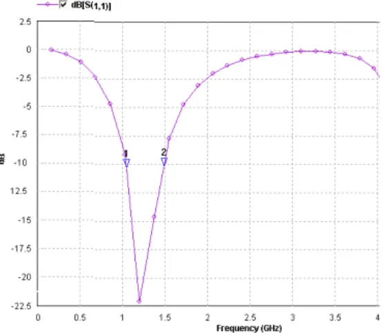
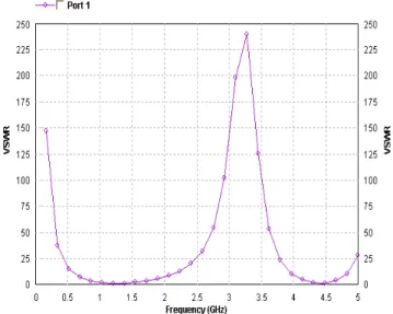
The input characteristics of the fabricated small-size Sierpienski & Crown Square Fractal Shapes Slotted Microstrip Patch Antennas [18] with different parameters are measured through a Vector Network Analyzer. Fig.2 shows the variation of return loss with frequency. Plot result shows resonant frequency 1.2 GHz. And total available impedance band width of 440 MHz that is 36.6% from the proposed antenna. Minimum -22.06 dB return loss is available at resonant frequency which is significant. Fig.3 shows the input impedance loci using smith chart. Input impedance curve passing near to the 1 unit impedance circle that shows the perfect matching of input. Fig.4 shows the VSWR of the proposed antenna that is 1.18 at the resonant frequency 1.2 GHz.
Fig. 2 Return loss vs. Frequency curve for proposed antenna.
In order to have a strong coupling among the element, a microstrip line is introduced between them. Then all the elements are coupled mostly by a guided wave through the microstrip line. Based on the measurement results, we can discuss the property of the proposed Sierpienski & Crown Square Fractal Shapes Slotted Microstrip Patch Antenna. From these results, it is observed that the proposed technique can achieve a maximum size reduction and better results that is good than the results obtained from other shapes.
IV CONCLUSIONS
Fig. 3 Input impedance loci using smith chart.
Fig. 4 VSWR vs. Frequency curve for proposed antenna
This novel design can be adjusted to work in higher frequencies which make it possible to add more slots and thus get higher gains. With the aim to preserve compactness requirements and to maintain the overall layout as simply as possible and keeping the realization cost very low.
[1] Bhattacharyya, A. K., and R. Garg, “Generalized Transmission Line Model for Microstrip Patches,” IEE Proc., Vol. 132, Pt. H, 1985, pp. 93-98.
[2] S. Silver, "Microwave Antenna Theory and Design", McGRAW-HILL BOOK COMPANY, INC, New York 1949. [3] Bhomia Y.,Chaturvedi A., Yadav D.,"Truncated Tip Triangular Microstrip Patch Antenna", Proc. IEEE. Int Symp. Antenna Propag.,vol. 2, pp. 212 -214, 2010.
[4] C. A. Balanis, "Antenna Theory, Analysis and Design", JOHN WILEY & SONS, INC, New York 1997. [5] K. F. Lee, Ed., Advances in Microstrip and Printed Antennas, John Wiley, 1997.
[6] Anzar Khan, Rajesh Nema, “Analysis of Five Different Dielectric Substrates on Microstrip Patch Antenna,” International Journal of Computer Applications ISSN 0975 – 8887, Volume 55, No.18, October 2012.
[7] R. Garg, P. Bhartia, I. Bahl, A. Ittipiboon, "Microstrip Antenna Design Handbook", ARTECH HOUSE, Boston 2001. [8] D. M. Pozar, "Input impedance and mutual coupling of rectangular microstrip antennas," IEEE Trans. Antennas and Propagation, vol. AP-30, pp. 1191-1196, Nov. 1982.
[9] James, J.R. and Hall, P.S.: ‘Handbook of Microstrip Antennas’ (Peter Peregrinus).
[10] Douglas H. Werner, Randy L. Haupt and Pingjuan L. Werner, “Fractal antenna engineering: The theory and design of fractal antenna array”, IEEE antennas and propagation magazine, Vol. 41, No. 5, pp. 37-59, October 1999.
[11] Bhomia, Y., A. Kajla, and D. Yadav, "Slotted right angle triangular microstrip patch antenna," International Journal of Electronic Engineering Research, Vol. 2, No. 3, 393-398, 2010.
[12] IE3D Software Release 9 and developed by M/S Zeland Software, Inc.
[13] Nazish Irfan, Mustapha C. E. Yagoub, and Khelifa Hettak, “Design of a Microstrip-Line-Fed Inset Patch Antenna for RFID Applications,” IACSIT International Journal of Engineering and Technology, Vol. 4, No. 5, October 2012, pp. 558-561.
[14] Indrasen Singh, V.S. Tripathi, “Micro strip Patch Antenna and its Applications: a Survey,” in IJCTA., Sep-Oct, 2011, vol. 2, No. 5, ISSN 2 2 2 9-6 0 93 , pp.1595-1599.
[15] F. E. Gardiol, "Broadband Patch Antennas," Artech House.
[16] D. M. Pozar and D. H. Schaubert, Microstrip Antennas: The Analysis and Design of Microstrip Antennas and Arrays, IEEE Press, 1995.
[17] H. F. Pues and A. R. Van de Capelle, "An Impedance Matching Technique for Increasing the Bandwidth of Microstrip Antennas," IEEE Trans. on Antennas and Propagation., Vol. AP-37, pp. 1345 - 1354, November 1989. [18] Yogesh Bhomia et.al., "V-Slotted Triangular Microstrip Patch Antenna", Int. Journal of Electronics Engineering, vol. 2,no.1, pp. 21- 23,2010.