w w w . a j e r . o r g Page 125
American Journal of Engineering Research (AJER)
e-ISSN: 2320-0847 p-ISSN : 2320-0936
Volume-03, Issue-11, pp-125-130
www.ajer.org Research Paper Open Access
Improving Microstrip Patch Antenna Directivity using EBG
Superstrate
Hayat Errifi
1, Abdennaceur Baghdad
2, Abdelmajid Badri
3, Aicha Sahel
41, 2, 3, 4
(EEA & TI Laboratory, Faculty of sciences and techniques/ Hassan II University Mohammedia-Casablanca, Morocco)
ABSTRACT: Electromagnetic Band-Gap (EBG) structures are popular and efficient techniques for microwave applications. EBG structures have two main configurations, first EBG substrate and second EBG superstrate. In first case, the patch of antenna is surrounded with EBG structure that suppress the propagation of surface wave and in second case, layer of EBG structure that call EBG superstrate set above the patch of antenna to increase the directivity and to reduce the side lobes of the radiation pattern. In this paper, we study the influence of the EBG superstrate on the performances of an aperture coupled rectangular microstrip patch antenna. The return loss, radiation pattern and directivity are studied using HFSS software. The simulation results show that the gain, directivity and S11 parameter of the antenna with EBG cover are increased at X band (8-12GHz). Compared with the patch feed with the same aperture size but without superstrate, the performance of the proposed antenna is significantly improved.
KEYWORDS : Patch antenna; HFSS; EBG Structure; Return Loss; Gain; and Directivity.
I. INTRODUCTION
Microstrip antennas are widely used in various applications because of low profile, low cost, lightweight and conveniently to be integrated with RF devices. However, microstrip antennas have also disadvantages such as the radiation of electromagnetic energy in different directions from radiation source (i.e. patch) witch cause the electromagnetic energy duo to the patch and feed of microstrip antenna, divide in all direction in the space that it results to reduce directivity, gain and wide radiation beam [1].BG structures are periodic structures that are composed of dielectric, metal or metallo-dielectric materials. These structures can prevent or assist wave propagation in special directions and frequencies therefore they can be used as spatial and frequency filters [2].There are several configurations of EBG structures according to their application in antenna. Two main configurations are:
a. EBG structures place on antenna substrate that by creation band gap in certain frequency range Suppress from propagation of surface wave. This configuration is defined as EBG substrate. In this configuration both of mushroom-like EBG and uniplanar EBG is used [3].
b. EBG structure place at certain distance above radiation source of antenna i.e. patch and by creation ultra-refraction phenomenon, concentrate radiation in various direction normal to EBG structure. This configuration is defined as EBG superstrate or Metamaterial superstrate and only the uniplanar EBG is used in this one [4].
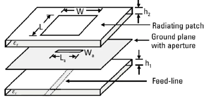
w w w . a j e r . o r g Page 126 Fig. 1: Geometry of the basic aperture coupled microstrip antenna
Fig. 1 represents conventional aperture coupled microstrip patch antenna. The basic microstrip patch antenna consists of three layers. The dielectric substrate is placed between a ground plane (lower layer) and radiating metallic patch (top layer). The proposed microstrip patch antenna is realized on the Roger RT/duroid substrate with permittivity ɛr=2.2 and thickness (h) of substrate is 0.79 mm, the ground plane and radiating patch is made of copper. The operating frequency of antenna (fr), at which we wish to achieve the maximum directivity, is 7 GHz. The dimension of radiating patch is calculated by equations (1), (2), (3) and (4) where L, W is length and width of radiating patch [5].
Effective dielectric constant is calculated from:
ɛ =ɛ�+1
2 +
ɛ�−1
2 1 +
12h
�
−1/2
(1)
Width of metallic patch:
W = c
2 � 2
ɛ�+1
(2)
Length of metallic patch:
L = Leff-2ΔL (3)
Calculation of length extension
��
ℎ = 0.412
ɛ +0.3 �
ℎ+0.264
1
ɛ −0.258 �
ℎ+0.8
1(4)
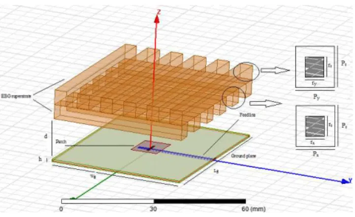
w w w . a j e r . o r g Page 127 Fig. 2: Geometry of the EBG patch antenna
EBG structure places above the patch of antenna for concentrating of radiation energy normal to itself.Fig. 2 shows configuration of microstrip antenna with EBG superstrate. The EBG material iscomposed of two layers, the first layer has a rectangular lattice (Px=12.7 mm, Pz= rZ), and the dielectric rods have a rectangular cross section (rx= 4mm, rz= 5mm), for the second layer it has a rectangular lattice (Py=15.72 mm, Pz= rZ), and the dielectric rods have a rectangular cross section (ry= 5mm, rz= 5mm). The cover has sex layers of rods in the x-direction, and sex layers in the y-direction (see Fig 2). The length of the rods (in the x and y direction)is chosen to be the same as the dimension of the ground plane. The distance between the substrate and the cover is chosen to be d = 14 mm.
The dielectric material is taken to have a dielectric constant ɛr= 9.2 which corresponds to the dielectric
constant of the "Rogers TMM 10 (tm)" in the microwave frequency range. Adjustment of first superstrate layer is the most important stage in antenna design and it is about one third of operation wavelength (λ/3) above ground plane which cause to gain increase. The second layer, improve beam shaping and directivity. The distance of second layer from first layer is taken almost zero.
Below, we will present the simulation results in terms ofthe computed radiation patterns, return loss and directivity of the proposed antenna. We use HFSS, which is 3D High Frequency Structure Simulator software [7].
II. SIMULATION RESULTS AND DISCUSSION
Now-a-days, it is a common practice to evaluate the systemperformances through computer simulation before the realtime implementation. A simulator “Ansoft HFSS” based onfinite element method (FEM) has been used to calculate return loss, radiation pattern and directivity. Thissimulator also helps to reduce the fabrication cost because only the antenna with the best performance would be fabricated [8].
Reflection characteristics : The reflection characteristic of the antenna design for high directivity operation is
shown in Fig. 3. For comparison the results are also presented for the aperture coupled feeding patch antenna without the EBG superstrate.
Fig. 3. Reflection coefficients of the source antenna with and without EBG structure
5.00 6.00 7.00 8.00 9.00 10.00
Freq [GHz] -30.00
-25.00 -20.00 -15.00 -10.00 -5.00 0.00
S1
1
(d
B)
HFSSDesign1
XY Plot 1 ANSOFT
m1
m2
m3
tw o layers EBG structure one layer EBG structure
w ithout EBG structure Name X Y
w w w . a j e r . o r g Page 128 Fig. 4. Results of directivity of an antenna with single layer and double-layer EBG superstrate as well as that of
the source antenna
To obtain an optimum response for directivity the air gap between the superstrate and the ground plane was varied to produce the final characteristic of directivity as shown in Figure4. The corresponding value is 14 mm. A maximum directivity of 11.78 dB is obtained at the frequency of 7GHz. Therefore it is important to control the air gap thickness in order to obtain a better performance from the antenna.
The maximum directivity of an aperture antenna is [10]:
(5)
Where A is the area of the aperture. Since A≈60 × 45 mm2 and λ = 37.5 mm in the present configuration, one has Dmax= 13.8 dB. The directivity of our designed EBG antenna (11.78 dB) is close to the
maximum directivity (13.8dB). That is physically possible for this size of antenna.
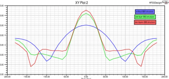
Radiation pattern and 3dB beamwidth : In figures (5 and 6)3-D radiation pattern of the antenna without EBG
superstrate and antenna with two layers EBG superstrate is shown. It is clear from these figures that directivity has been improved by 6.71dB and total efficiency of Antenna increased from 36% to 85%.
Fig. 5. 3D-Radiation pattern of microstrip antenna without EBG superstrate showing directivity of 5.07 dB -200.00 -150.00 -100.00 -50.00 0.00 50.00 100.00 150.00 200.00
Theta [deg] -20.00
-15.00 -10.00 -5.00 0.00 5.00 10.00 15.00
D
ire
ct
ivi
té
(d
B)
HFSSDesign1
XY Plot 2 ANSOFT
one layer EBG structure tw o layers EBG structure w ithout EBG structure
w w w . a j e r . o r g Page 129 Fig. 6.3D-Radiation pattern of microstrip antenna with two layers EBG superstrate showing directivity of 11.78
dB
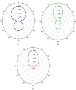
Fig. 7 displays Radiation pattern for the double layer EBG superstratebased antenna, a single layer EBG superstrate based antenna and the feed antenna.
Fig. 7. Radiation pattern of (a) simple microstrip antenna (b) antenna with one layer EBG structure (c) antenna with two layersEBG structure
w w w . a j e r . o r g Page 130
III. CONCLUSION
In this paper, aperture coupled microstrip patch antenna with EBG superstrate has been studied. The main impetus for studying this antenna structure with EBG superstrate was the desire to realize increased directivity without using complex structures such as SRR (Split Ring Resonator) superstrate. The directivity characteristics of the composite structure have been investigated by using HFSS software, which has been found to be a useful tool for designing antennas of this type. Finally, it was found that both the directivity level, beamwith as well as reflection coefficient could be further enhanced by using EBG superstrate with two layers, rather than one. A very important need is to verify more of the simulation results with experimental measurements which will be reported in future work.
REFERENCES
Books:
[1] R. Garg, “Microstrip Antenna Design Handbook”, Artech House, London, 2001
[2] F. Yang, “Electromagnetic Band Gap Structures in Antenna Engineering”, Cambridge Universuty press, 2009
Journal Paper:
[3] sh. zhu, and R. Langley, “Dual band Wearable Textile Antenna on an EBG Substrate “, IEEE transaction on antenna and propagation,
Vol. 57, pages 926-935 (2009)
Proceedings Paper:
[4] Dalin Jin, Bing Li , And Jingsong Hong, “gain improvement of a microstrip patch antenna using metamaterial superstrate with the zero
refractive index”, Microwave and Millimeter Wave Technology conferece (ICMMT), page 1-3 (2012)
Book:
[5] Balanis CA. Antenna theory, analysis and design. New York: John Wiley & Sons, Inc.; 1997.
Journal Paper:
[6] H. Errifi, A. Baghdad, A. Badri, “Design and optimization of aperture coupled microstrip patch antenna using genetic algorithm”,
International Journal of Innovative Research in Science, Engineering and Technology,ISSN: 2319-8753, Vol. 3, Issue 5, May 2014.
Book:
[7] HFSS software user guide.
Journal Paper:
[8] Mst. Nargis Aktar, Muhammad Shahin Uddin, Monir Morshed, Md. Ruhul Amin, and Md. Mortuza Ali, Enhanced gain and bandwidth
of patch antenna using EBG substrates”. International Journal of Wireless & Mobile Networks (IJWMN) Vol. 3, No. 1, February 2011.
Proceedings Paper:
[9] Basit Ali Zeb and Karu P. Esselle “A Simple EBG structure for dual-band circularly polarized antennas with high directivity”, in Proc. IEEE AP-S Int. Symp., 978-1-4673-0462-7/12/$31.00 ©2012 IEEE.
Journal Paper:
[10] Min Qiu and Sailing He “High directivity patch antenna with both photonic bandgap substrate and photonic band gap cover,