Comparison on the Reception Property of Gunn Mounted ASRA
and AMPA
Somnath Chatterjee1*, B. N. Biswas2
(1) Kanailal Vidyamandir (Fr. Section), Chandernagore, Hooghly 712136, West Bengal. India (2) Sir J. C. Bose School of Engineering, SKF Group of Institutions, Mankundu, Hooghly, West Bengal- 712139
Copyright 2013 © Somnath Chatterjee and B. N. Biswas. This is an open access article distributed under the Creative Commons Attribution License, which permits unrestricted use, distribution, and reproduction in any medium, provided the original work is properly cited.
Abstract
A Gunn mounted active microstrip patch antenna (AMPA) and active microstrip slot antenna (ASRA) has been investigated for the reception of FM microwave signal. Current well/valley phenomenon has been successfully utilized to demodulate the modulation information. Reception poperty of the both antennas are studied in multi-channel environment. Because of its simple circuit configuration and similarity in transmitter and receiver architecture, active patch antenna as demonstrated is well suited for commercial and military application as a two-way microwave communication system.
A comparative study on the role of AMPA and ASRA as a receiver shows that ASRA do better performances than AMPA. In case of ASRA the modulating signal are demodulated without any distortion. ASRA also has large locking range (29 MHz) compare to AMPA (5 MHz). So the ASRA has broad band tuning capabilities than AMPA. With ASRA configuration demodulation bandwidth in excess of 14 MHz is realizable which can successfully accommodate a large number of voice or data channels.
Keywords: Active microstrip patch antenna (AMPA), active microstrip slot antenna (ASRA)
1 Introduction
Active microstrip antennas are potentially attractive for realizing large aperture phased array antennas suitable for satellite and space based communication [1]. They also offer an effective alternative to conventional phase and adaptive arrays for a few commercial application [2], short range microwave communication, LAN’s, microwave identification systems [3]. The reasons are quite obvious: they offer savings in size, weight, cost and improved efficiency over conventional designs. Active microstrip antennas function as RF oscillator as well as efficient radiator. A large number of such active antenna elements are integrated to perform the function of both transmission and reception. A huge number of experiments/studies [5, 6] have been made about the radiation performance of an antenna (slot and patch both) though studies on its reception performance are really a few. Some of them are operated in
self-Available online at www.ispacs.com/acte Volume 2013, Year 2013 Article ID acte-00138, 9 Pages
mixing receiving mode and proposed for signal detection. Recently self mixing Gunn mounted active antennas have been reported [3, 4] at L-band for a half duplex communication system and at X-band for transceiver and spatial power combining applications.
An active antenna is basically an oscillator and then a radiator, its device characteristic under injection locked condition shows an interesting modification [5-20]. In this paper, a detailed comparative study in case of reception of a FM signal between active microstrip patch antenna (AMPA) and active microstrip slotted ring antenna (ASRA) has been discussed. Conventional Discriminator output also studied here. Over the lock band AMPA and ASRA exhibits the phenomenon of FM-AM conversion [13, 18, 21-23]. This results in a lock-in FM detector, where both the functions of FM-AM conversion and square law detection are combined.
2 System Equation
A sinusoidal signal of frequency
1 acting on a nearly sinusoidal oscillator of frequency
o affects itsbehavior in many respects depending on the strength and frequency of the forcing signal. A forcing signal when injected into an oscillator modifies its properties in many ways. The analytical equivalent circuit of an oscillator under the influence of a forcing signal is represented in Fig.1. Within the synchronization range the locked oscillator loses its identity and obeys command from the forcing signal, and the oscillator is said to be injection locked (phase locked) to the synchronization signal. The system equations of injection locked Gunn oscillator (ILGO) can be expressed as
2
3
cos
2
4
2
o o
d d
V
dV
V
E
dt
Q
Q
(1)and
sin
2
2
o c o o
o c
d
E
d
dt
Q V
dt
(2)where
m
sin
mt
represents an FM signal at X-band and
d,
d = constants of Gunn diode.R C L Gu nn d iod e In ject ion sig na l - d v- d v 2 + d v 3
Ii I
inj
Figure1: Equivalent circuit of an injection locked oscillator
E
cos
y
cos
t
Q
V
V
Q
dt
dA
o k k o2
4
3
2
2 (3)
dt
d
t
sin
y
sin
V
E
Q
dt
d
o oo
o
2
2
11 , (4)
where
t
sin
m
,
mi
1 .Figure 2: Experimental arrangement for observing, demodulation property by an active antenna
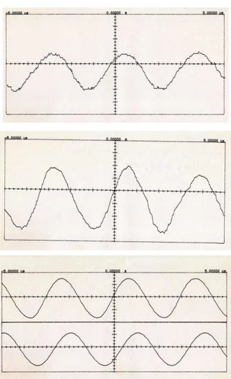
Solutions of the coupled equations are obtained through simulation in MathCAD. We have taken the modulating signal as a sinusoidal one of 1.0 MHz with a modulation index of 0.122. Total Q of the active patch antenna is 150,
40
MHz
. The amplitude and phase responses are plotted in Figs.6(a) and6(b). Effect of interference noise is easily visible in these figures. The same response characteristics were
observed with a low pass filter [
,
s
s
F
1
1
=filter time constant]. Filtered output of the detected
signal is almost free from noise as indicated in Figs.7(a) and 7(b).
3 Active antenna configuration
A rectangular patch and a slotted ring antenna has been designed by etching on a Taconic TLY-5 substrate with a relative dielectric constant r =2.2, thickness h=0.787 mm. The conducting material has
Table 1a: Antenna dimensions for rectangular patch
Design frequency fo GHz
Length l mm
Width w mm
Position of the diode l1 mm
Characteristic impedance Z0 Ohm
9.5 10.202 14.569 4.33 12.951
Table 1b: Antenna dimensions for slotted ring
Mean radius of the ring 4.216 mm
Width of the slot 1 mm
No of section of quarter wave transformer 7
Characteristic impedance 158.057
Position of the diode 13.2 mm from the mouth of the antenna
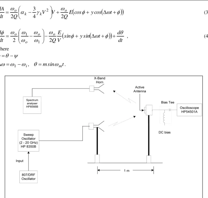
Figure 5: Demodulated output of the same FM signal.
(a)received by a standard horn
(b)received by AMPA
(c)received by ASRA
(d)information signal Figure 3: Injection locking of the active patch antenna.
Lock range
5.3 MHz.The diode is screw mounted onto the patch by drilling a hole through the substrate. Dc bias is applied to the diode through an rf choke realized by means of designing a hi-lo type two section transformer. The Gunn diode used was an M/A COM 49104-111 rated for a minimum continuous wave (CW) power output of 25 mW.
Figure 6(a): Amplitude modulation of an ILGO Figure 7(a): Amplitude modulation of an ILGO locked to locked to an FM signal. FM signal. The FM is accompanyed with an interference. FM signal is accompanyed by an interference signal. Filtered output is shown.
Figure 6(b): Phase modulation of an ILGO Figure 7(b): Phase modulation of an ILGO locked to locked to an FM signal. an FM signal. The FM is accompanyed by an FM signal is accompanyed by an interference signal. interference signal. Filtered signal is shown.
4 Experimental Observation
4.1. Detection performance of the active antenna
microwave carrier. The receiving antenna is placed at a line-of-sight distance of 1.0 metre away from the transmitting one. The modulated signal is transmitted through the horn antenna, which irradiates the active patch. Frequency of the transmitted microwave carrier is suitably tuned so that it gets locked to the (a) patch oscillator (b) slot oscillator. Active patch oscillator shows an approximate capture range of 6.0MHz. Whereas the Active Slot Ring Antenna shows the capture range of the order of 29 MHz. that is very large compared to AMPA. Injection locked oscillator radiation is received by another similar type X-band horn antenna. The details have been observed on a spectrum analyzer (8566B from HP) connected to the horn as shown in Fig.2. Injection locking of the active patch antenna is shown in Fig.3. It shows an approximate Locking range
5.3 MHz. Injection locking of the active slot antenna is shown in Fig.4. It shows an approximate Locking range
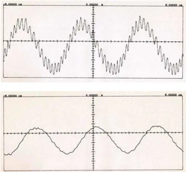
29.2 MHz. From the detected output (Fig. 5) it was clear that for better reception ASRA is much appropriate than AMPA. Fig.5a shows the detected signal demodulated by a conventional discriminator (with the help of microwave counter HP 2590B) of the FM signal received by a standard x band horn antenna.Figure 8: 1 MHz tone signal received by ASRA (In presence of noice) (a) before filtering and (b) after filtering
4.2. Detection performance of the active antenna in presence of interfering signal
The reception capability of active antenna has been tested in multi-channel (two channel in our case) environment. An interference signal is chosen as noise generated from a (Marconi Inst 6158A) source. It has been placed 95 MHz away from the microwave carrier frequency. The interference carrier has been power combined with the microwave FM signal in a 10 dB coupler in order to transmit both the carriers simultaneously. The detected signal has been obtained at the ac port of the bias T. The information signal becomes heavily corrupted by beat frequency noise as shown in Fig 8(a). The beat frequency noise has been removed by using a passive low pass filter. Oscillogram of the filtered signal is shown in Fig 8(b).
5 Conclusion
approximate capture range of 5.0MHz. Whereas the ASRA shows the capture range of the order of 29 MHz. that is very large compared to AMPA. With the present system configuration demodulation bandwidth in excess of 2.0 MHz is realizable which can successfully accommodate quite a large number of voice or data channels. The proposed receiving scheme is unique in the sense that it does not require IF electronics for the purpose of demodulation. It also works well in a multi-channel environment due to the excellent noise-squelching property of an Injection Locked Gunn Oscillator. Because of its simple circuit configuration and similarity in transmitter and receiver architecture, active patch antenna as demonstrated is well suited for commercial and military application as a two-way microwave communication system. A comparative study on the role of AMPA and ASRA as a receiver shows that ASRA do better performances than AMPA. In case of ASRA the modulating signal are demodulated without any distortion. ASRA also has large locking range (29 MHz) compare to AMPA (5 MHz). So the ASRA has broad band tuning capabilities than AMPA. With ASRA configuration demodulation bandwidth in excess of 14 MHz is realizable which can successfully accommodate a large number of voice or data channels. The proposed receiving scheme with ASRA is unique in the sense that it does not require IF electronics for purpose of demodulation and it has a very large locking bandwidth.
References
[1] S. Sanzgire, W. Pottenger, D. Bostrom, D. Demiston, R. Q. Lee, Active Sub-array Module Development for Ku-band Satellite Communication Systems, IEEE AP-Symposium Digest, Seattle, Washington, (1994) 860-863.
[2] R. A. York, T. Itoh, Injection and phase locking technique for beam control, IEEE Trans. Microwave Theory Tech, 46 (11) (1998) 1920-1929.
http://dx.doi.org/10.1109/22.734513
[3] C. M. Montiel, L. Fan, K. Chang, A novel active antenna with self-mixing and wideband varactor-tuning capabilities for communication and vehicle identification applications, IEEE Trans. Microwave Theory Tech, 44 (12) (1996) 2421-2430.
http://dx.doi.org/10.1109/22.554572
[4] C. M. Montiel, L. Fan, K. Chang, An X-band self-mixing oscillator antenna for transeceiver and spatial power combining applications, IEEE Trans. Microwave Theory Tech, 46 (10) (1998) 1546-1551.
http://dx.doi.org/10.1109/22.721163
[5] B. N. Biswas, A. Bhattacharya, D. Mondal, P. Lahiri, A. Bose, S. Pal, Rectangular active microstrip patch antennas revisited, IETE J of Research, 45 (2) (1999) 135-145.
[6] P. A. Ramsdale, T. S. M. Maclean, Active loop-dipole aerials, Proc. of IEE, 118 (12) (1971) 1698-710.
http://dx.doi.org/10.1049/piee.1971.0313
[7] B. M. Armstrong, R. Brown, R. Fix, J. A. C Stewart, Use of microstrip impedance-measurement technique in the design of a BARITT diplex Dopper sensor, IEEE Trans. Microwave theory Tech, 28 (12) (1980) 1437-1442.
[8] K. Chang, K. A. Hummer and G. Gopalakrishnan, Active radiating element using FET source integrated with microstrip patch antenna, Electron. Lett, 24 (21) (1988) 1347-1348.
http://dx.doi.org/10.1049/el:19880916
[9] J. A. Navarro, Y. Shu, K. Chang, Active end fire antenna elements and power combines using notch antennas, IEEE-MTT Microwave Symp. Dig. Technical Papers, (1990) 793-796.
[10] W. A. Fritz, P. E. Mayes, A Frequency –scanning Strip line-fed periodic slot array, IEEE AP-S Int. Symp. Digest, (1974) 278-281.
[11] J. S. Rao, B. N. Das, Impedance of off-centered Strip line Fed Series Slot, IEEE Trans. on Antennas and Propagation, 26 (1978) 893-895.
http://dx.doi.org/10.1109/TAP.1978.1141964
[12] I. J. Bhal, P. Bhartia, Microstrip antennas, Artech House, (1980).
[13] B. N. Biswas, A. Bhattacharya, D. Mondal, P. Lahiri, A novel scheme for reception using an active microstrip antenna, IEEE Trans. Microwave Theory Tech, 48 (10) (2000) 1765-1768.
http://dx.doi.org/10.1109/22.873908
[14] B. N. Biswas, A. Bhattacharya, D. Mondal, A. Bose, S. Pal, Active rectangular microstrip antenna revisited, IETE J. of Research, 45 (2) (1999) 135-145.
[15] N. A. Navarro, K. Chang, Integrated Active Antenna and Spatial Power Combining, John Wiley & Sons, NY (1996).
[16] T. Durga Prasad, K. V. Satya Kumar, M. D. Khwaja Muinuddin, Chisti B.Kanthamma, V.Santosh Kumar, Comparisons of Circular and Rectangular Microstrip Patch Antennas, International Journal of Communication Engineering Applications-IJCEA, 02 (04) (2011).
[17] M. K. Mandal, P. Mondal, S. Sanyal, A. Chakrabarty, An Improved Design Of Harmonic Suppression For Microstrip Patch Antennas, Microwave and Optical Technology Letters, 49 (1) (2007) 103-105.
http://dx.doi.org/10.1002/mop.22049
[18] S. Chatterjee, A. Bhattacharaya and B. N. Biswas, Active Rectangular Patch Antenna - A New Design Philosophy, International Journal of Electronics and Communication Engineering & Technology (IJECET), 3 (1) (2012) 220-228.
[19] S. Chatterjee, B. N. Biswas, Active Slot-Ring Antennas Demodulates while it receives, accepted for publication in International Journal on Communications Antenna and Propagation (IRECAP), (2012).
[21] S. Chatterjee, A. Bhattacharya, B. N. Biswas, Active Rectangular Patch Antenna-A new Design Philosophy, International Journal of Electronics and Communication Engineering & Technology (IJECET), (2012) 220-228.
[22] S. Chatterjee, B. N. Biswas, Simultaneous Oscillation in Gunn Oscillator, Journal of Electron Devices (France), 14 (2012) 1128-1131.