American Journal of Engineering Research (AJER)
e-ISSN : 2320-0847 p-ISSN : 2320-0936
Volume-02, Issue-09, pp-23-30
www.ajer.org
Research Paper Open Access
Enhancing the Bandwidth of a Microstrip Patch Antenna using
Slots Shaped Patch
Atser A. Roy, Joseph M. Môm, Gabriel A. Igwue
Department of Electrical and Electronics Engineering, University of Agriculture, Makurdi, Nigeria
Abstract: - In this work, three different geometry shapes, the U, E and H are developed from a rectangular patch of the width (W) = 32mm and length (L) = 24mm. The proposed antennas are simulated using Sonnet software and the results compared with the conventional rectangular patch antenna. The results obtained clearly show that, bandwidth of conventional rectangular microstrip antenna can be enhanced from 4.81% (100MHz) to 28.71% (610 MHz), 28.89% (630MHz) and 9.13% (110MHz) respectively using U, E and H-patch over the substrate. The E-shaped patch antenna has the highest bandwidth followed by U-shaped patch antenna and H-shaped patch antenna. The substrate material used for the proposed antennas is Alumina 96%, with the dielectric constant of 9.4 and loss tangent of 4.0e-4. The proposed antennas may find applications in Wireless Local Area Network (WLAN).
Keywords: -bandwidth, dielectric constant, microstrip antenna, slot patch, substrate
I. INTRODUCTION
Communication can be broadly defined as the transfer of information from one point to another [1]. Communication between human beings was first done through voice. With the desire to increase the distance of communication, devices such as Drums, signal flags and smoke were used. These optical communication devices of course utilized the light part of the electromagnetic spectrum. It has been of recent in human history that the electromagnetic spectrum, outside the visible region has been employed for communication, through the use of Radio. One of the greatest human scientific evolutions is the emergence of electromagnetic spectrum and antenna has been instrumental in harnessing the resource. Through the years, microstrip antenna structures are most common option used to realize millimeter wave monolithic integrated circuits for microwave, radar and communication purposes. The shape and operating mode of the patch are selected, designs become very versatile in terms of operating frequency, polarization, pattern and impedance [2].
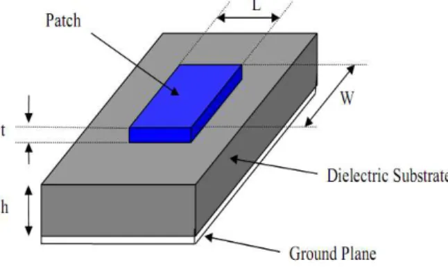
Microstrip patch antenna consists of a radiating patch which is generally made of conducting material such as gold or copper and can take any possible shape. The radiating patch and the feed lines are usually photo etched on the dielectric substrate which have a ground plate as shown in Fig. 1.
In order to simplify analysis and performance prediction, the patch is generally square, rectangular, circular, triangular, and elliptical in shape.
For a rectangular patch, the length L of the patch is usually 0.333λo < L< 0.5λo, where λo is the free
space wavelength. The patch is selected to be very thin such that the patch thickness t<<λo. The height h of the
dielectric constant of the substrate (Ԑr) is typically in the range 2.2 ≤ Ԑ ≤12. The microstrip patch antennas
radiate primarily because of the fringing fields between the patch edge and the ground plane. For good antenna performance, the choice of substrate used is an important factor. There are numerous substrates that can be used for the design of microstrip antennas within the dielectric constants range of 2.2 ≤ Ԑ ≤12. The low dielectric constantԐ is about 2.2 to 3, the medium around 6.15 and the high approximately above 10.5[1].
A thick dielectric substrate having a low dielectric constant is desirable since this provides better efficiency, larger bandwidth and better radiation. However, such a configuration leads to a larger antenna size. In order to design a compact microstrip patch antenna, substrate with higher dielectric constants must be used which are less efficient and result in narrower bandwidth. Hence a trade-off must be realized between the antenna dimensions and antenna performance [3].
II. DESIGN METHODOLOGY
2.1 Design Equations
The effective dielectric constant � is given as
� =Ԑ + 1
2 +
Ԑ −1
2 1 +
12 �
−1/2
(1)
Where, Ԑr = Dielectric constant, h = height of dielectric substrate, w = width of the patch. The Hammerstad formula for the fringing extension is [4]
∆�
= 0.412 Ԑ
+ 0.3 + 0.264
Ԑ −0.258)( + 0.8) (2)
The effective length of the patch Le now becomes
Le = L + 2∆� (3)
The resonance frequency for the (1, 0) mode is given by
0=
2� √Ԑ (4)
Where C is the speed of light.
2.2 Feeding Techniques
Microstrip patch antennas can be fed by a variety of methods. These methods can be classified into two categories-contacting and non-contacting methods. The RF power is fed directly to the radiating patch using a connecting element such as a microstrip line. In the non-contacting scheme, electromagnetic field coupling is done to transfer power between the microstrip line and the radiating patch [2]. The four most popular feed techniques used are the microstrip line, coaxial probe (both contacting schemes), aperture coupling and proximity coupling (both non-contacting schemes).
2.3 Method of Analysis
There are many methods of analysis for microstrip antenna. The most popular models are the transmission-line, cavity and full-wave. The transmission-line model is the easiest of all, it gives good insight and it is adequate for most engineering purposes and requires less computation. However, it is less accurate. The cavity model is more accurate and gives good physical insight but is complex [5]. The full-wave models are very accurate, very versatile, and can treat single elements, finite and infinite arrays, stacked elements, arbitrary shaped elements and coupling. However, they are the most complex models and usually give less physical insight.
2.4 Bandwidth
interval for determining the bandwidth of the antenna. Bandwidth is presented more concisely as a percent where
% =∆ × 100 (5)
Where ∆f is the width of the range of acceptable frequencies, and fo is the resonant frequency of the
antenna [6]. The expressions for approximately calculating the percentage BW of the (RMSA) antenna in terms of patch dimensions and substrate parameters is given by [7].
% = ×
� √� � (6)
Where A is constant, and can take the values 180, 200 and 220. for A = 180
� √� ≤0.045
for A = 200
0.045≤
� √� ≤0.075
for A = 220
� √� ≤0.07
With an increase in W, bandwidth increases. However, W should be taken less than λ to avoid excitation of higher order modes. The BW of the MSA can also inversely proportional to its quality factor Q and is given by [3].
= −1
√ (7)
The BW is usually specified as frequency range over which VSWR ≤ 2. However, in recent years considerable effort has been spent to improve the bandwidth of the microstrip antenna, in part by using alternative feeding schemes [8].
2.5 Return Loss
The return loss is another way of expressing mismatch. It is a logarithmic ratio measured in dB that compares the power reflected by the antenna to the power that is fed into the antenna from the transmission line. The relationship between VSWR and return loss is as follows [9].
� = 20� 10
−1 8
III. ANTENNA DESIGN AND ANALYSIS
The designed parameters for the proposed patch antenna were calculated using (1) – (4) and presented Table 1.
TABLE 1: Antenna Parameters Frequency of operation fo 2GHz
Height of Substrate (h) 2mm Dielectric constant (εr) 9.4
Width of the Patch (W) 32mm Length of the Patch (L) 24mm
The proposed antenna is to be used for the wireless local area network (WLAN). The antenna is to operate in the frequency range from 1GHz to 3GHz. The dielectric material selected is Alumina 96% which has a dielectric constant of 9.4. The dielectric constant is kept high in order to get a reduced antenna size. The objective is to get an improve bandwidth from the conventional rectangular patch since the higher dielectric substrate results in size reduction at the expense of bandwidth reduction.
In this design, we have proposed three different geometry shapes the U, H and E from a patch of width (W) = 32mm and length (L) =24mm. The three proposed antennas are simulated using Sonnet software, under the same conditions and results compared with the conventional rectangular patch antenna, and the shape with improve bandwidth is adopted, and implemented. The bandwidth was obtained where return loss is less than -10dB which is an acceptable level to describe the loss of the power which reflects back from the antenna without being radiated.
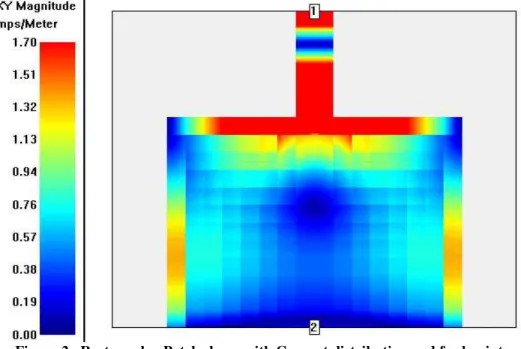
Fig. 2, shows the geometry of conventional rectangular microstrip antenna (RMSA). The antenna is designed for the resonance frequency of 2GHz. It consists of radiating patch of length L and width W.
Figure 2. Rectangular Patch shape with Current distribution and feed points
Fig. 3, shows the geometry of E-shaped radiating patch fabricated from the rectangular patch.
U and H are also fabricated from the same patch size as shown in Fig. 4 and Fig. 5 respectively.
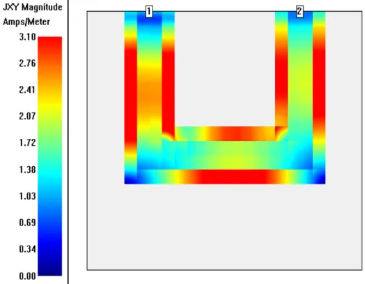
Figure 4. U- Patch shape Antenna with Current distribution and feed points
Figure 5. H-Patch shape Antenna with Current distribution and feed points
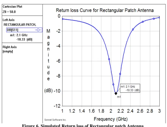
Figure 6. Simulated Return loss of Rectangular patch Antenna
From the graph, the experimental bandwidth is calculated using the formula
% = − � × 100 (9)
Where, and � are upper and lower cut-off frequencies of the bandwidth respectively when its return loss reaches -10dB and is the center frequency between and � .
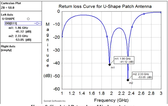
Figure 8. Simulated Return loss of U- shape Antenna
Figure 9. Simulated Return loss of H-shaped patch Antenna
The percentage bandwidth of the conventional RMSA is found to be 4.81% with bandwidth of 100MHz.The expressions for approximately calculating the percentage bandwidth of the RMSA in terms of patch dimensions and substrate parameters is given by [7].
% = ×
� √� � (7)
Where, A is constant, which is found to be 180 [7]. The BW calculated using equation (6) is 4.52% which is not too far from experimental result.
Figure 6, shows the variation of return loss versus frequency of E- shape patch antenna. The antenna resonates at two bands of frequencies 1.74GHz and 2.49GHz. This development is as a result of the slots. The overall bandwidth at (1.74GHz and 2.49GHz) is found to be 28.89% (that is 630MHz).
Figure 7, shows the variation of return loss versus frequency of U-shaped patch antenna. The antenna resonates at two bands of frequencies at 1.96GHz and 2.33GHz, due to the U-slots. The overall bandwidth is 28.71 (that 610MHz).
This clearly shows that slot can be either resonant or non-resonant. If it is resonant, the current along the edges of the slot introduces additional resonances near the patch resonance, adding them together causes enhancement in the bandwidth.
Figure 6 and figure 7 give the highest bandwidth of 28.89% (630MHz) and 28.71% (610MHz) which is more than bandwidth of conventional RMSA. This further enhancement in bandwidth when compare to RMSA is as a result of insertion of slots used for the construction of E and U-shaped patches. The current along the edges of the slot induces an additional resonance, which adds to the fundamental resonance of the radiating element that helps to increase bandwidth [10].
IV. CONCLUSION
In this work, the aim was targeted at improving the bandwidth of microstrip antennas constructed with dielectric material with higher dielectric constant. We have selected three different patch antennas and the simulated results compare with the conventional microstrip patch antenna. The results obtained clearly show that bandwidth of conventional RMSA made with dielectric substrates having higher dielectric constants can be improved using U and E-shaped patch antenna. We have observed that E-shaped patch antenna has the highest bandwidth follow by U-shaped patch antenna and H-shaped antenna.
REFERENCES
[1] K.T Ahmed, M. B Hossain and M.J Hossain, “Designing a high bandwidth patch Antenna comparison with the former patch Antenna” Canadian journal on multimedia and wireless network Vol.2, No. 2 April,2011.
[2] S.K Behera, “Novel Tuned Rectangular Patch Antenna as a load for phase power combining” Ph.D Thesis, Jadavpur University, Kolkata, India.
[3] C. A Balanis, “Antenna Theory Analysis and Design” Wiley, 2nd edition, chapter 14. 1997
[4] J. R James and P. S Hall, “Handbook of microstrip Antennas” Volume 2. Peter Peregrinus Ltd, London,
1989.
[5] H. Pues and A. V Capelle, “Accurate transmission-line model for the rectangular microstrip antenna, “Proc. IEEE, vol. 131, no.6, pp. 334-340, December 1984.
[6] I. J. Bahl and P. Bhartia, “Microstrip Antenna” Artech House, 1980.
[7] K. P Ray, “Broadband, dual-frequency and compact microstrip Antennas” Ph.D Thesis, Indian Institute
of Technology, Bombay, India, 1999.
[8] D. R Jackson and J .T Williams, “A comparison of CAD models for radiation from rectangular microstrip
patch,” Intl. Journal of microwave and millimeter-wave computer Aided Design, vol 1, no.2 pp.236-248,
April 1991.
[9] http://wireless.ictp.it/handbook/C4.pdf
[10] G. Z Rafi and L. Shafai, “wider band V-slotted diamond-Shaped microstrip patch antenna, “Electronics
letters, vol. 40, no. 19, 1166-1167, 2004.