Journal of Engineering Science and Technology Review 6 (2) (2013) 164-167
Research Article
Research on Cylindrical Surface Wave Plasma Fluorescent Lamps
Kun WANG 1, 2, Jian LI 1, 2* and Jing Xiao3
1Southwestern Institute of Physics, Chengdu, 610041, China
2Engineering and Technical College of Chengdu University of Technology, Leshan, 614007, China
3Air force Logistic College,XuZhou 221000,China
Received 15 May 2013; Accepted 25 July 2013
___________________________________________________________________________________________
Abstract
This paper presents an application of the well known SPWM technique on a voltage stabilizer, using a microcontroller. The stabilizer is AC/DC/AC type. So, the system rectifies the input AC voltage to a suitable DC level and the intelligent control of an embedded microcontroller regulates the pulse width of the output voltage in order to produce through a filter a perfect sinusoidal AC voltage. The control program on the microcontroller has the ability to change the FET transistor firing in order to compensate any input voltage variation. The applied software using the microcontroller’s interrupts managed to achieve concurrency on the running program.
Keywords:Microcontroller Embedded Control, Power Systems Applications, Power Electronics, SPWM
__________________________________________________________________________________________
1. Introduction
Microwave and RF plasmas are finding increasing use in many fields [1-3]. A plasma column can be constructed in a glass tube filled with low pressure gases with a SWP source. This discharge style has many merits in plasma antennas and lighting [4]. The principal properties of the plasma, ion density and electron temperature have much influence on the application of lighting [3, 4]. The related diagnosis system is seldom referred. Gas discharge lamps give out 70% light of artificial lamps with only 30% illumination electricity energy in the earth. The gas discharge lamps are usually driven by two pole electrodes power supply. The one-pole fluorescent lamps driven by a SWP system is also seldom referred.
A SWP generator and a Langmuir double probe system are designed in our lab. A cylindrical quartz tube and a commercial cylindrical fluorescent lamp with the same diameter 26 mm are selected for test. Principal properties of the plasma, ion density and electron temperature and the luminance of the fluorescent lamps are tested and researched. Factors influencing the plasma and the luminance, such as the microwave power and the gas pressure, were studied. The radial and axial distribution of plasma and luminance were researched.
2. Experimental Setup
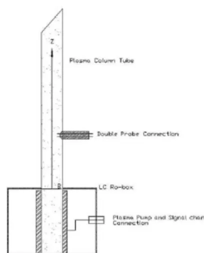
Fig. 1 shows the schematic diagram of the SWP generator. The SWP generator can be connected to a cylindrical quartz tube or a commercial cylindrical fluorescent lamp. LC-box
[5] is taken as the pump method. The input power of the wave generator is tested by the power meter. The power is 20~80W. 100 MHz microwave is generated by a generator designed in our lab. A quartz cylindrical tube with 26 mm in diameter and 1200 mm in length has several Langmuir double probes every 200 mm from the base along the tube. A vacuum system with base vacuum 4×10⁻³ Pa is used to obtain the needed pressure. High purity gases act as the working gases. A commercial cylindrical fluorescent lamp is driven by the SWP generator and tested. The luminance distribution is tested by a luminance meter. The Langmuir double probe made of tungsten and glass locates at every 200 mm from the base. The naked part length of the probe is 1 mm. The data can be attained from the V-I figures in different conditions [6]. A curve called the double probe characteristic of the plasma will be obtained and the electron temperature and ion density in the plasma can be calculated from the double probe characteristic [1-6].
Fig. 1. Schematic diagram of the SWP generator.
J
estr
JOURNAL OF Engineering Science andTechnology Review
www.jestr.org
______________
* E-mail address:[email protected]
Kun WANG, Jian LI and Jing Xiao/Journal of Engineering Science and Technology Review 6 (2) (2013) 164-167
165
3. Results and discussion
3.1 Electron temperature and Ion density
3.1.1 Electron temperature and Ion density vs. Gas pressure or Power
The electron temperature and ion density which are decided by the gas pressure and the power are the main properties of the plasma in the lamp. A cylindrical quartz tube is used to test the luminance distribution. The mixture of 0.5% argon and 99.5% neon acts as the working gas. The pressure ranges from 0.5 Pa to 50 Pa and the power is fixed at 60 W. Keep the pressure 2 Pa and the power changed at 20-80 W. Fig. 2 shows the relationships between electron temperature, ion density and the gas pressure or power of the fluorescent lamps. With the pressure increasing, the electron temperature and ion density decreased. The ion density decreases firstly and increases a bit subsequently. The electron temperature and ion density both increase with the power.
The frequency of elastic and inelastic bumping increased with the pressure increasing. The electrons can’t acquire enough paths to accelerate to a higher speed. The electrons with lower energy can’t ionize more neutral atoms [2-4, 7], which caused the electron temperature and the ion density decreased. Frequently bumps at higher pressure leads to higher ionization rate and plasma density. The luminance depended on the ion density. The electron temperature and ion density both increased with the power. The microwave power increment leads to the electric field increasing at the vacuum room edge, which caused the increase of the hot electrons and more neutral gas molecules were ionized.
0 10 20 30 40 50
1.3 1.4 1.5 1.6 1.7 1.8 2 4 6 8 ni Te (e V) ni (1 0 17m -3) Pressure (Pa) Te
30 40 50 60 70 80
0 1 2 3 4 5 6 7 8 0.0 0.5 1.0 1.5 2.0 2.5 3.0 3.5 4.0 4.5 5.0 Te (eV) ni (10 17m -3) Power (W)
ni(Z=1000mm)
ni(Z=20cm)
Te(Z=1000mm)
Te(Z=200mm)
Fig. 2. Ion density and Electron temperature vs. Pressure or Power at 200 mm at P=60 W.
3.1.2 The radial and axial distribution of electron temperature and ion density
The SWP plasma process decides the distribution of the electron density and the ion temperature. In the application of antennas and lamps, the radial and axial distribution of plasma is of great importance. The radial and axial distribution of the cross section average electron temperature and ion density is sketched in Fig. 3. The electron temperature and the ion temperature may decrease with the length and increase with the radius.
The electron temperature is the function of the pressure and the radius. When the power is fixed, electron temperature will increase with radius. The plasma is produced along the surface of the quartz tube. As the frequency of the driven source is much lower than that of the plasma, the plasma is like a metal and the microwave can only propagate along the inner surface of the tube [12]. Higher microwave power density caused higher ion density and higher electron temperature. This is why this kind of plasma is called surface wave sustained plasma.
0 20 40 60 80 100 120
1 2 3 4 5 6 7 2.0 2.2 2.4 2.6 2.8 3.0 0 0 0 0 0 0 ni Te (e V) ni (1 0 17m -3) Length (mm) Te
0 3 6 9 12
2.5 3.0 3.5 4.0 4.5 5.0 5.5 6.0 6.5 7.0
0 3 6 9 12
1.0 1.2 1.4 1.6 1.8 2.0 2.2 2.4 2.6 2.8 3.0 ni Te (eV ) ni (10 17m -3) Radius (mm) Te
Fig. 3. Radial and axial distribution of Ion density and Electron temperature at 200 mm. P=2 Pa and Power=60 W.
3.2 Luminance
3.2.1 Luminance vs. Microwave Power or Illumination Length
Kun WANG, Jian LI and Jing Xiao/Journal of Engineering Science and Technology Review 6 (2) (2013) 164-167
166
is found that the luminance increased with the input microwave power.
The microwave power increasing leads to the electric field increasing at the edge of the vacuum room, which causes more neutral molecules ionized. The higher plasma density will lead to higher recovery rate, which causes the higher luminance. Keep the generator power be 60 W, the luminance is tested every 200 mm above the base. In Fig. 4, the luminance decreases with the length increasing. The plasma density decreases with the length increases until the plasma density is low enough not to sustain the surface wave to propagate [13,14]. The lower plasma density causes the lower luminance.
30 40 50 60 70 80
4500 5000 5500 6000 6500 7000 7500 8000 8500
Lu
mi
na
nce
(C
d/m
2)
Power (W)
20 40 60 80 100
3000 4000 5000 6000 7000 8000 9000
0 0
0
0 0
Lu
mi
na
nce
(C
d/m
2)
Length (mm)
Fig. 4. Luminance vs. Power or Illumination Length at Z=200 mm at P=60 W.
3.2.2 Illumination length and Microwave power
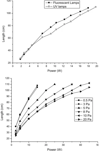
A commercial cylindrical fluorescent lamp and a commercial cylindrical ultraviolet lamp with the same length and radius 1200 mm and 26 mm are chosen for the experiment. They were driven by the SWP generator shown in Fig. 1. The illumination length is tested with a ruler. The lamps may be turned on when the power is only about 2 W and the length of the illumination part is about 200 mm. The length may increase when the power grows. The relationships between the illumination length and the microwave power in the fluorescent lamp and ultraviolet lamp are shown in Fig. 5. The power of the SWP generator changes from 2 to 20 W. The length of the illumination increases with the power [13].
0 2 4 6 8 10 12 14 16 18 20
20 40 60 80 100 120
L
e
n
g
th
(c
m)
Power (W)
Fluorescent Lamps UV lamps
0 10 20 30 40 50
20 30 40 50 60 70 80 90 100 110 120
L
e
n
g
th
(c
m)
Power (W)
0.5 Pa 3 Pa 5 Pa 8 Pa 10 Pa 20 Pa
Fig. 5. Illumination length vs. Microwave Power in commercial cylindrical fluorescent and ultraviolet lamps; Illumination length vs. Microwave Power at different Pressure.
Fig. 5 shows the relationship between the illumination length and the power in the quartz tube at different pressures. The mixture of 0.5% argon and 99.5% neon acts as the working gas. The pressure ranges from 0.5 Pa to 20 Pa. The length increases with the power at any pressure. At lower pressure, the length increases more significantly. The bumping rate between molecules enhances with the pressure increasing. The power is wasted, which lead to not enough power to excite more gases at longer position [12-14].
4. Conclusions
Kun WANG, Jian LI and Jing Xiao/Journal of Engineering Science and Technology Review 6 (2) (2013) 164-167
167
lamp driven by the SWP generator is a one-pole driven lamp. It is suit for both plasma antennas and fluorescent
lamps.
______________________________ References
1. Wang Kun, Li Jian. Design of Surface-wave Sustained plasma Flat Panel Lamps [C], Advanced Materials Research 2013; Vols. 756-759:188-191.
2. Wang Kun, Li Jian, Wang Shiqing. Research on the luminous efficiency of gas discharge flat panel lamps [J], Vacuum 2012;.49(6):83-86.
3. Li Jian, Wang Kun. Research in Surface-wave Sustained plasma Fluorescent Lamps [C], Advanced Materials Research 2013; Vols. 756-759:184-187.
4. Wang kun, Li jian, Wang Shiqing, Optimization of Xenon Gas Discharge Flat Panel Lamps [C], Advanced Materials Research 2012; vol. 571:256-260.
5. Li Jian, Wang Kun, Wang Shiqing, Research in luminous efficacy of the mercury free plasma flat panel lamps [J], Nuclear Fusion and Plasma Physics 2012;32(1):92-96.
6. Li Jian, Wang kun, Wang Shiqing, Flat Panel Ultrovilet Lamps by vehicle of Porous Alumina and ITO glass [C], 2nd International Conference on Electronic & Mechanical Engineering and Information Technology(EMEIT-2012) 2012;1026-1029.
7. Wang Kun, Li Jian, Wang Shiqing. Penning Effects on Characteristics of Surface Wave Sustained Plasma [J], Chinese Journal of Vacuum Science and Technology 2009;29(3):264-267.
8. Li Jian, Wang kun, Wang Shiqing, Double Probe Diagnosis of Surface-Wave Sustained Plasma Column [C], 2nd International Conference on Electronic & Mechanical Engineering and Information Technology(EMEIT-2012) 2012;1030-1033.
9. Li Jian, Wang Kun, Wang Shiqing, Influence of He-Ar Penning process on the power SWP column [J], Vacuum 2012; 48( 5):25-28. 10. Moisan and Z Zakrzewski, Plasma Sources based on the propagation of electromagnetic surface waves [J], J. Phys. D 1991;24:1025-1034.
11. Jhon Phillip Rayner, Adrian Philip Whichllo, and Andrew Desmond Cheetham, Physical characteristics of plasma antennas [J], IEEE Transaction on Plasma 2004;32(1):269-281.
12. Liu, J., W.-Y. Yin, and S. He, A new defected ground structure and its application for miniaturized switchable antenna [J], Progress In Electromagnetics Research 2010;107:115-128.
13. Wang shiqing, Yan zelin, Li Wenzhong, Liu Jian, Li Jian, Xu Lingfei, Study of Propagation Characteristics of Plasma Surface Wave in the Medium Tube[J], Plasma Science and Technology 2008; 10(6):671-675.