A Framework for Modelling Software Requirements
Dhirendra Pandey1, Ugrasen Suman.2, A.K. Ramani2
1
Member IEEE, Department of Information Technology, Babasaheb Bhimrao Ambedkar University,
Lucknow-226025, India
2 Schools of Computer Science & IT,
Devi AhilyaVishwavidyalaya, Indore, MP, India
,
Abstract
Requirement engineering plays an important role in producing quality software products. In recent past years, some approaches of requirement framework have been designed to provide an end-to-end solution for system development life cycle. Textual requirements specifications are difficult to learn, design, understand, review, and maintain whereas pictorial modelling is widely recognized as an effective requirement analysis tool. In this paper, we will present a requirement modelling framework with the analysis of modern requirements modelling techniques. Also, we will discuss various domains of requirement engineering with the help of modelling elements such as semantic map of business concepts, lifecycles of business objects, business processes, business rules, system context diagram, use cases and their scenarios, constraints, and user interface prototypes. The proposed framework will be illustrated with the case study of inventory management system.
Keywords: Requirement Modelling, Inventory Control and Management System, Requirement Engineering (RE).
1. Introduction
Requirement Engineering (RE) is the process of collecting, analyzing and modelling software requirements in a systematic manner [1, 2, 3]. Requirement modelling is the major challenge of automotive software development [4]. One of the main problems of RE is to describe the requirements in terms of concise and manageable formal models and to integrate models to form a consistent and complete understanding of the software to be developed. Requirements modelling and analysis are the most important and difficult activities in the software development. Software development is becoming more mature by advancing development processes, methods, and tools. The famous Christ Honour and Other Served (CHAOS) has reported the statistics published by Standish Group show that still only about one third of software projects can be called successful, i.e. they reach their goals within planned budget and time [5]. Research on
post-mortem projects’ analysis shows that the major problems comes when the requirements elicitation, analysis, specification, and management is not performed regularly. Deploying successful requirements process in a concrete organization is an important issue for software practitioners [6, 7]. While companies continue to use text-based documents as major means for specifying and analyzing requirements, the graphical requirements modelling are getting increasingly more attention in industry. This trend has increased after Object Management Group (OMG) standardized Unified Modelling Language (UML) [8]. As we know, that a picture is worth a thousand words. It is also applies in requirements analysis, where business people have to communicate with software developers, who do not know their domain and speak a different technical language. Additionally, UML tools support refining requirements models with design and implementation details for enabling traceability, validation, prototyping, code generation and other benefits. In large software development projects, these features are very important for evolving and managing requirement models.
community was not satisfied by UML, and created a new Business Process Modelling Notation (BPMN), which has become OMG standard as well. In many cases, they also apply Integration Definition for Function Modeling (IDEF) notations [12, 13]. In domain analysis, analysts continue to apply old-style Entity Relationship (ER) notation, which was popular in database design since 70s [141]. A significant attention is paid to business goals, business rules, business object lifecycles, business roles and processes in organization, which also can be done using UML [15, 16].
Real-time and embedded system developers have also come up with a different flavour of UML – System Modelling Language (SysML). It defines requirements diagram and enables capturing various non-functional and detailed functional requirements [17]. Also, it establishes specific links between requirements and other elements. Most popular requirements text books introduce various diagrams based on both UML and other informal notations, e.g. system context diagram, and hand-drawn user interface prototypes [11, 18]. The mentioned requirements artefacts can be modelled using UML. Since UML is a general purpose modelling language with more than 100 modelling elements (UML meta classes) and without standardized method, practitioners apply it only fragmentally, and at the same time, they do not make use of its powerful capabilities to define consistent, integrated, and reusable requirements models. Various researches have already been performed to produce framework for creating UML models for MDD (Model-Driven Development) [12, 15]. This paper extends it with more focus on the details of a specific part of the framework by applying UML concepts for requirements modelling.
Most requirement documents are written in natural languages and represented in less structured and imprecise formats. Including requirement phase, artifacts created in phases of software life cycle are required to be modelled and integrated, so the traceability, consistency, and completeness can be ensured [19, 20]. The Organisation of paper as follows. We propose an effective framework for requirement modelling using some demonstrated examples, which is discussed in detail with various phases in Section 2. Future scope of this research is discusses in section 3. Finally, Section 4 describes the concluding remarks.
2. Requirements modelling framework
Most requirement documents are written in ambiguous natural languages which are less formal and imprecise. Without modelling the requirement documents, the
knowledge of the requirement is hard to understand [17, 18]. The lack of framework for guiding requirements models is one of the main issues. In academic community, researchers propose many detailed and focused requirements development methods [20, 21]. However, most of these methods resulting from academic research are too complex for practical application and solve just specific specialized issues. A simple and adaptable framework for requirements modelling with demonstrated examples are created using available tools on a realistic case study gives much more value for practitioners.
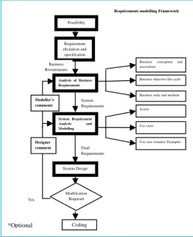
We have proposed requirements modelling framework using UML concepts for model-driven software development, which is shown in Figure 1. This framework consists of five major phases, namely; feasibility study, requirement collection and specification, analysis of business requirements, system requirement modelling and system design. Further, analysis of business requirements includes business conception and association, business object life cycle and business tasks and methods and system requirement modelling incorporates actors, use cases and their scenario. The following subsections will discussed each phases of the proposed framework with the help of UML diagram and using examples.
Figure 1: Requirement Modelling Process
2.1 Feasibility Study
Feasibility study starts when the developer faces the problem in existing system and hence recognizes a need for developing/ improving the system. It aims to
Analysis of Business Requirements
System Requirement Analysis and Modelling
Business conception and association
Business objective life cycle
Business tasks and methods
Use cases
Use case scenario/ Examples Actors
Requirements modelling Framework
Requirement elicitation and specification
System Design Designer
comment Modeller’s comments
Feasibility
System Requirements Business
Requirements
Draft Requirements
Modification Required Yes
Coding
objectively and rationally uncover the strengths and weaknesses of the existing business or proposed venture, opportunities and threats as presented by the environment, the resources required to carry through, and ultimately the prospects for success. In its simplest term, the two criteria to judge feasibility are cost required and value to be attained. As such, a well-designed feasibility study should provide a historical background of the business or project, description of the product or service, accounting statements, details of the operations and management, marketing research and policies, financial data, legal requirements and tax obligations. Generally, feasibility studies precede technical development and project implementation.
2.2 Requirement elicitation, collection and specification
Requirement elicitation and development phase mainly focuses on examining and gathering desired requirements and objectives for the system from different viewpoints (e.g., customer, users, constraints, system's operating environment, trade, marketing and standard etc.). Requirements elicitation phase begins with identifying stakeholders of the system and collecting raw requirements from various viewpoints. Raw requirements are requirements that have not been analysed and have not yet been written down in a well-formed requirement notation. The elicitation phase aims to collect various viewpoints such as business requirements, customer requirements, user requirements, constraints, security requirements, information requirements, standards etc.
Typically, the specification of system requirements starts with observing and interviewing people [1, 2, 3]. Furthermore, user requirements are often misunderstood because the system analyst may misinterpret the user’s needs. In addition to requirements gathering, standards and constraints are also play an important role in systems development. The development of requirements may be contextual. It is observed that requirement engineering is a process of collecting requirements from customer and environment in a systematic manner. The system analyst collects raw requirements and then performs detailed analysis and receives feedbacks. Thereafter, these outcomes are compared with the technicality of the system and produce the good and necessary requirements for software development [3].
Requirements requirement specification (SRS) document is produced after the successful identification of requirements. It describes the product to be delivered rather than the process of its development. Also, it includes a set of use cases that describe all the interactions
that users will have with the system/software [2]. In addition to use cases, the SRS also contains non-functional requirements. Non-functional requirements are requirements which impose constraints on the design or implementation. SRS is a comprehensive description of the intended purpose and environment for software under development. The SRS fully describes what the software will do and how it will be expected to perform. An SRS minimizes the time and effort required by developers to achieve desired goals and also minimizes the development cost. A good SRS defines how an application will interact with system hardware, other programs and users in a wide variety of real-world situations. Parameters such as operating speed, response time, availability, portability, maintainability, footprint, security and speed of recovery from adverse events are evaluated in SRS.
2.3 Analysis of business requirements
Many organizations already have established their procedures and methodologies for conducting business requirements analysis, which may have been optimized specifically for the business organization. However, the main activities for analysing business requirements are identifying business conception and association, determining business object life cycle, and identifying business tasks and methods. If these exist, we can use them. However, we must follow the following factors to create requirement models:
(A) Identification of key stakeholders- The first step toward
the requirement analysis and collection is Identification of the key people who will be affected by the project. Such as, project's sponsor responsible users and clients. This may be an internal or external client. Then, identify the end users, who will use the solution, product, or service. Our project is intended to meet their needs, so we must consider their inputs.
(B) Capture stakeholder requirements- Another approach
towards analysis of business requirement is capturing the requirement from stakeholders. In this approach, the requirement engineer requests stakeholders or groups of stakeholders for their requirements from various sources for the new product or service.
(C) Categorize requirements- Requirements can be
classified into four categorized to make analysis easier for software design:
Functional requirements (FR) – FR defines how a
Operational requirements (OR) – OR operations
that must be carried out in the background to keep the product or process functioning over a period of time.
Technical requirements (TCR) – TCR defines the
technical issues that must be considered to successfully implement the process or create the product.
Transitional requirements (TSR) – TSRs are the
steps needed to implement the new product or process smoothly. TSR is indicates that how the requirements are behave as the consequence of external requirements
(D) Interpret and record requirements- Once we have
gathered and categorized all requirements determine which requirements are achievable, and how the system or product can deliver them. The following steps should be taken to interpret the requirements:
Define requirements precisely – Ensure that the
requirements are not ambiguous or vague, clearly worded, sufficiently detailed, related to the business needs and listed in sufficient detail to create a working system or product design.
Prioritize requirements – Although many
requirements are important, some are more important than others, and budgets are usually limited. Therefore, identify which requirements are the most critical, and which are less.
Analyze the impact of change – carry out an impact
analysis to make sure that we understand fully the consequences our project will have for existing processes, products and people.
Resolve conflicting issues – Sit down with the key
stakeholders and resolve any conflicting requirements issues. We may find scenario analysis helpful in doing this, as it will allow all those involved to explore how the proposed project would work in different possible futures.
Analyze feasibility – Determine reliability and
easy-to-use the new product or system. A detailed analysis can help identify any major problems.
Business conception and association: Different
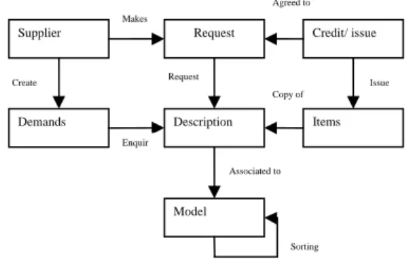
methodologists have been proposed by various researchers for business conception and association techniques but still disagree on beginning of business information systems development [10]. In our proposed research, the starting point should be business concept analysis and analysis and their relationships which are shown in Figure 2. For this purpose we can apply simple organisational working model using only classes with names and without more
detailed information, associations with names and role multiplicities. Such models are discussed by business analysts and domain experts who are usually not familiar with object-oriented analysis and design.
Therefore, it is very important that all the other elements of the model, such as aggregations, compositions, generalizations, interfaces, enumerations, etc., should not be used for conceptual analysis. Keeping it simple enables even UML novices to understanding it after getting a little explanation. Additionally, we can provide textual descriptions for each of these concepts and generate printable or navigable domain vocabularies. We believe this should be the first artifact since it sets up the vocabulary, which should be used for defining other requirement model elements, cases, etc.
Figure 2: Analysis model for business conception and association
Business object life cycle: Requirements models are used
when gathering requirements, and during systems analysis. Whether we consider eliciting requirements to be a separate activity, or a part of systems analysis, the importance of correct requirements must be a high priority for us. Building accurate models means that we can guarantee the correctness of our requirements. All engineering disciplines use models to develop the products they intend to build. Requirements models are used to discover and clarify the functional and data requirements for software and business systems. Additionally, the requirements models are used as specifications for the designers and builders of the system.
Organizations have business rules for managing business objects. In many cases, business rules regulate how important business objects change states and are applicable only when object is in a particular state. Requirement modelling is one of the important tools to understand these changes. The states also serve as a part of terminology, which will be used in other business and requirements models. State machine diagrams should be created only for those business concepts that have dynamic
Supplier Request Credit/ issue
Demands
Model
Description Items
Sorting Enquir
Create
Agreed to
Issue Copy of
Associated to Makes
states. Business modellers should define triggers on all transitions in state diagram.
In business modelling for transition triggers, most people use informal signals that in most cases correspond to actions of business roles. Also, time and property change triggers are used to express various states changes according to time or data based business rules. It is possible to define inner triggers that happen inside one state and doesn’t fire a transition. In inventory management system, register (data store) is checking for availability of reservation for supplier. If available, supplier is assigned by a unique id to them and after that issue the item. Manufacturer notifies the overdue of product item and after one year the identified item will be notified as lost or damaged. Example of this concept is shown in Figure 3.
Figure 3: Business object lifecycle in Inventory Control and Management System
Business tasks and methods: After learning domain
terminology and business rules concerning lifecycles of business objects, we can identify business tasks and methods, and associate roles to processes in which they are involved.
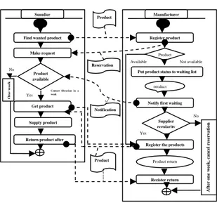
Figure 4: Inventory system process (tasks and methods)
We recommend to model business roles with actors, and business processes, if modellers need to visually separate it from system actors and use cases. The business roles association to business processes is best done within specialized use case diagram or editable relationship matrix.
In Figure 4, we are showing inventory processes with the supplier and manufacturer role perspectives. The role of supplier and manufacturer are different. Supplier starts the work with finding the wanted product at manufacturer site. Supplier makes reservation for the product; if the reservation is available he gets the item. After supplying the product he can be return the product due to damage or complaining by the customer with in prescribed date.
The first step in moving from domain analysis to requirements definition is use case analysis. We propose to do use case analysis using different steps such as identify the actors and group them into primary (main users), secondary (administration, maintenance, and support), external systems, and pseudo (e.g. time). We have defined main system use cases in a sketch use case diagram using pictorial form in figure 4.
The manufacturer registers the reservation of product, which is requested by the supplier. If the product is available, he may issue it to the supplier. If not, manufacturer put the reservation to the waiting list until the product is not available. On availability, manufacturer notify to the first waiting supplier (Supplier is too many). Otherwise he may cancel the reservation after prescribed date. The business processes are usually modelled in two forms, i.e. “as is”, represents current situation, and “to be”, represents target situation that should be reached after
Supplier Manufacturer
Find wanted product
Make request
Get product
Return product after Supply product
Product available
O
n
e
w
eek
Contact librarian in a week
Put product status to waiting list
Notify first waiting
Register the products Register product
Register return Product Available Not available
product
Supplier regularity
No
Yes No
Yes
After o
n
e week
, ca
n
cel
reserv
a
ti
o
n
Product return Product
Reservation
Notification
Product
Available
Entry / checking for any demands
Assigned
Entry/ notify about availability
Issued
Issue at timely return/ Notify about overdue Register
Lost
After 1 Year
Damaged Lost
After maximum pending time
Issue
Waiting order Cancel/ Notify
In progress
Re
tur
n
Re
tur
automation or refactoring [10]. For software developers it is important to know which parts in target business processes the software system should implement or support.
2.4 System requirements modelling using case study
Requirement modelling is an important activity in the process of designing and managing enterprise architectures. Requirements modelling helps to understand, structure and analyse the way business requirements are related to Information Technology requirements, and vice versa, thereby facilitating the business-IT alignment. It includes actors, use cases and use case scenario. Each of these is further describe in following subsection:
Actors: An actor is a user or external system with which a
system being modelled interacts. For example, in our inventory management system involves various types of users, including supplier, inventory management system, human resources, and manufacturer. These all users are actors. At the same time, an actor is external to a system that interacts with the system. An actor may be a human user or another system, and has some goals and responsibilities to satisfy in interacting with the system.
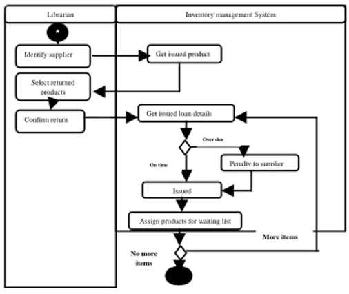
It is also necessary to generate actor who giving compact overview of the whole model. We have to prepare requirement specification model that incorporates the package details diagram, showing package use cases, their associations with actors and relationships between use cases including uses cases. For making good requirement modelling system engineer prepares activity diagrams visualizing scenarios of complex use cases. In model, the activities should be nested within appropriate use cases and assigned as their behaviours. And finally we describe use cases according to pre-defined templates, e.g. rational unified process use case document, actors in Figure 5.
Figure 5: Issueing the product for supplier
Use case and Use case scenario: A use case in software
engineering and systems engineering is a description of a potential series of interactions between a software module and an external agent, which lead the agent towards something useful. A use case diagram in the UML is a type of behavioral diagram defined by and created from a Use-case analysis. The purpose of use case is to present a graphical overview of the functionality provided by a system in terms of actors, their goals and any dependencies between those use cases. Also, it is useful to show what system functions are performed for which actor.
Requirement models are used to captures only functionality that the end-user needs from the system. The other requirements such as non-functional requirements or detailed functional requirements are not captured in standard requirement modelling diagrams. The simplest way is to describe those in simple textual format and include references to use cases, their scenarios, etc. Another approach is to create specific requirements modelling.
Figure 6: Register product return
For example, introduce stereotypes for each important requirement type with tags consisting requirement specific information and define types of links for tracing requirements, such as derive, satisfy, support. Another aspect on which system analyst’s work in some projects is definition of data structure. It can be done using conventional requirement modelling diagrams. If necessary, object diagrams can also be used for defining samples for explanation or testing of data structure defined in class diagrams. Since the focus here is on data structure, class operations compartments can be hidden in the diagram (Figure 6).
Identify supplier
Select returned products
Confirm return
Librarian Inventory management System
Get issued product
Get issued loan details
Penalty to supplier
Issued
Assign products for waiting list
Over due
On time
More items No more
items
Find product
Make request
Make the reservation
Review supplier profile
Register issued product
Register product return
Penalize supplier
Notify about availability
Include
Product info system Supplier
Time Inventory System
Manufacturer
Extend (Waiting reservation)
Extend (Waiting reservation)
Extend Due to Overdue
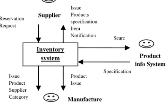
Comparing to conceptual analysis, more elements are used here, such as attributes and association end specifications, enumerations, and generalization. Although such model is considered to be part of design, in practice quite often it is created and maintained by system analysts. For data-centric applications, it is very important to do data-flow diagrams showing information flows between different classifiers, e.g. system-context diagram indicates information flows from system to outside world entities, i.e. actors or external systems that need to be integrated.
Figure 7: Information flow model
The previous requirements modelling artifact for which system analyst might be responsible is user interface prototypes. The prototype itself can theoretically be mapped to UML Composite Structure diagram. However, when focusing on separate screen prototypes, people sometimes loose the screens which can be used by each actor, and the possibilities to navigate from each screen to the other screens. For capturing this information, we can create GUI navigation map, which is shown in Figure 7. In Figure 7, we use state diagram, where each state represents a screen, in which user is at the moment, and transition triggers represent GUI events, such as mouse double-click or clicking on some button, Using this requirement model, system developers create an effective software on inventory control and management system. The user interface diagram model is shown in Figure 8.
Figure 8: User interface diagram model
Finally, we emphasize that the requirements analysis work should be iterative and incremental. Also, the ordering of modelling tasks might be different based on taken approach, or some steps might be omitted.
2.5 System design
After the successful completion of system requirement and modelling phase, the draft (raw) requirement may be provided to the design team. Design team check the validity of these draft requirements and starts to design the system or software model. Basically, system design is the process of designing developing and implementation of the proposed system as per the requirement obtained during the analysis of existing system. The main objective of the system design is to develop the best possible design as per the requirements from users and working environment for operating the information system. It is the process of defining the architecture, components, modules, interfaces, and data for a system to satisfy specified requirements. Systems design is therefore the process of defining and developing systems to satisfy specified requirements of the user. Object-oriented analysis and design methods are becoming the most widely used methods for computer systems design. The UML has become the standard language in object-oriented analysis and design. It is widely used for modelling software systems and is increasingly used for high designing non-software systems and organizations.
After the designing of the system model, designer evaluates the efficiency of the design model. If any modification is remaining in the model, designer again checks the validity of requirements and asks for correction with comments. The process will stopped until the clear cut clarification is not received by the design team. This section is very important because according to the software engineering approach the design is the bridge the gap between requirement analysis and coding of the final software development
3. Discussion and future scope
The paper discusses implementation of requirement modelling for various requirements analysis purposes and mapping of conventional requirements artifacts into system elements. We have also presented some modelling aspects, which are necessary for ensuring that the requirements elements that are mapped to the same UML element can be differentiated. We can also find critics on using UML as requirements specification language, most of the issues can be solved using UML tool with rich
Entry the Supplier information Supplier Profile
Login
Issuing detail Home
Issue details
Reservation details Reservation detail
Home
Product Browse
Browse Browse
Select category/ Refresh Titles
Product Detail
Search
On - match
Multiple Matches
Get detail Browse
Make reservation Cancel reservation
Supplier
Inventory
system Product
info System
Manufacture
Issue Product Supplier Category
Product Issue
Searc
Specification Issue
Products specification Item Notification Reservation
possibilities for modelling environment customization and extensions [18]. On the other hand, there are also suggestions to use more UML for requirements analysis and visualizations [20]. Multiple authors provide numerous papers on more detailed approaches to customizing unified modelling language for specific requirements modelling needs, such as analyzing scenarios, modelling user interface prototypes, refining requirements [21, 22]. Some researchers also suggest that UML can be specialized for early phase requirements gathering process but the proposed framework emphasizes that early phase modelling should focus on same types of artifacts with less detail.
4. Conclusions
In this paper, we have discussed the major requirements artifacts described in requirements engineering literature can easily be mapped to elements of UML. Also, we have depicted a conceptual framework for requirements modelling with illustrated examples for inventory control and management system. Our future research work will focus on more detailed management for requirements modelling framework and development of different demo version for different management system.
References
[1] D. Pandey, U. Suman, A. K. Ramani, Social-Organizational Participation difficulties in Requirement Engineering Process- A Study, National Conference on ETSE & IT, Gwalior Engineering College, Gwalior,2009.
[2] Dhirendra Pandey, U. Suman, A.K. Ramani, Design and Development of Requirements Specification Documents for Making Quality Software Products, National Conference on ICIS, D.P. Vipra College, Bilaspur, 2009.
[3] Dhirendra Pandey, U. Suman, A.K. Ramani , An Effective Requirement Engineering Process Model for Software Development and Requirements Management, IEEE Xplore, 2010, Pp 287-291
[4] M. Broy, I. Kruger, A. Pretschner and C. Salzmann. Engineering Automotive Software. Proceedings of THE IEEE. 95(2): 356-373, Febrary 2007.
[5] D. Rubinstein Standish Group Report: There’s Less Development Chaos Today. SD Times, March 1, 2007.
[6] J. Aranda , S. Easterbrook , G. Wilson Requirements in the wild: How small companies do it. 15th IEEE International Requirements Engineering Conference (RE 2007), pp. 39-48.
[7] M. Panis, B. Pokrzywa, Deploying a System-wide Requirements Process within a Commercial Engineering Organization. 15th IEEE International Requirements Engineering Conference (RE 2007), pp. 295- 300.
[8] Object Management Group. Unified Modelling Language: Superstructure. Formal Specification, 15th IEEE International Requirements Engineering Conference (RE 2007), 2007.
[9] G. Engels., R. Heckel, and S. Sauer, UML – A Universal Modelling Language? In M. Nielsen, D. Simpson (Eds.): ICATPN2000, LNCS 1825, pp. 24-38, 2000.
[10] I. Jacobson, Object-Oriented Software Engineering. Addison Wesley Professional, 1992.
[11] K. Wiegers. Software Requirements. 2nd edition, Microsoft Press, 2005.
[12] Object Management Group. Business Process Modelling Notation Specification. Final Adopted Specification, version 1.0, 2006. [13] O. Noran. UML vs. IDEF: An Ontology-oriented Comparative
Study in View of Business Modelling. Proceedings of International Conference on Enterprise Information Systems, ICEIS 2004, Porto, 2004.
[14] P. Chen, P.-S. The entity-relationship model – toward a unified view of data. ACM Transactions on Database Systems (TODS), vol. 1 (1), 1976.
[15] Van Lamsweerde, A. Goal-Oriented Requirements Engineering: A Guided Tour. RE'01 – International Joint Conference on Requirements Engineering, Toronto, 2001, pp.249-263.
[16] M. Penker , H. Eriksson, E. Business Modelling With UML: Business Patterns at Work. Wiley, 2000.
[17] Object Management Group. Systems Modelling Language. Formal Specification, version 1.0, 2007.
[18] E. Gottesdiener, The Software Requirements Memory Jogger: A Pocket Guide to Help Software and Business Teams Develop and Manage Requirements. GOAL/QPC, 2005.
[19] M. Glinz, Problems and Deficiencies of UML as a Requirements Specification Language. 10th International Workshop on Software Specification and Design, 2000, p.11 - 22
[20] S. Konrad, H. Goldsby, K. Lopez, Visualizing Requirements in UML Models. International Workshop REV’06: Requirements Engineering Visualization, 2006.
[21] H. Behrens, Requirements Analysis and Prototyping using Scenarios and Statecharts. Proceedings of ICSE 2002 Workshop: Scenarios and State Machines: Models, Algorithms, and Tools, 2002.
[22] Da Pinheiro, P. Silva, The Unified Modelling Language for Interactive Applications. Evans A.; Kent S.; Selic B. (Eds.): UML 2000 – The Unified Modelling Language. Advancing the Standard, pp. 117-132, Springer Verlag, 2000.
Dhirendra Pandey is a member of IEEE and IEEE Computer
Society. He is working in Babasaheb Bimrao Ambedkar University, Lucknow as Assistant Professor in the Department of Information Technology. He has received his MPhil Degree in Computer Science from Madurai Kamraj University, Madurai, Tamilnadu, India. Presently, he is perusing PhD in Computer Science from School of Computer Science & Information Technology, Devi Ahilya University, Indore (MP).
Dr. Ugrasen Suman has received his PhD degree from School of
Computer Science & Information Technology (SCSIT), DAVV, Indore. Presently, he is a Reader in SCSIT, Devi Ahilya University, Indore (MP). Dr. Suman is engaged in executing different research project in SCSIT. He has authored more than 30 research papers.
Professor (Dr.) A. K. Ramani has received his ME and PhD