!"#$ !% &
' (!" !) !"#* ( !) !"#
! " # $ %& ' $(% ) * " $ %
(A)
Research Scholar, Department of Mechanical Engineering, Anna University, Coimbatore 641047, Tamil Nadu, India.
(B)
Director of Research, Mechanical Engineering, Karpagam University, Coimbatore 641021, Tamil Nadu, India.
(C)
Associate Professor, Department of Mechanical Engineering, P.S.G.college of Technology, Coimbatore 641004, Tamil Nadu, India.
Corresponding Author E mail: [email protected], TEL: 09894479240, 09710266805
+We present the performance of dry sliding metal metal wear performance of AISI SS410 and Ti C N coated specimens at room temperature. In this investigation, the ball cratering abrasive wear testing method was used with a various loads of 2N, 3N and 4N, with total sliding distance of 353.43 m and at a constant sliding speed of 0.3927 ms1. In this testing machine the abrasive ball of high carbon steel with 750 HV at 100 g load is rotated against the Ti C N composite coated and uncoated AISI SS410. The worn surfaces were examined with scanning electron microscopy (SEM) (with EDAX attachment). The more grooving region, pits, ploughing ridge were found on the worn surface of the high carbon steel.
, # +Friction and wear resistant; TiCN-SEM EDAX; PVD coating
. +
In modern internal combustion engines mechanical losses increases due to friction 4 and 15% of the total energy consumed /.0. Mechanical losses of about 40% 55% occur in the power cylinder /10, and the piston ring generated half of the power cylinder friction losses /.& 2& 30. Recent studies show that 80% of the total cost for the protection of metals is related to coating application /40. Deposition of coatings provide a way of extending the limits of the use of the materials and their performance capabilities, by allowing the mechanical properties of the substrate materials to be maintained while protecting against wear, oxidation and corrosion
/50. Tribological failure like scuffing failure occurs which is characterized by a sudden rise in friction, contact temperature, vibration and noise, resulting in a surface roughening through severe
plastic flow and loss of surface integrity /6& 70. The physical vapour deposition (PVD) techniques are widely used nowadays for improvement of the mechanical, corrosion protection capability and other properties, of a broad range of engineering materials /8& .90. The TiN coating was developed in the early 1970s /..0 and this hard coating is an important role in surface engineering parts for two decades because of high hardness over 20 GPa
/.10. As one of the major milestones in the advances of hard coating development, TiAlN has been commercially very successful due to significantly improved oxidation resistance and hardness over TiN /.2 .70. Use of real engine tests for the evaluation of tribological performance is very costly and time consuming. One way to speed up the process, while maintaining accuracy of the prediction, is to
'' 9863 : 9435
!"#$ !% & develop mathematical models for each wear
mechanism. In this work investigates to determine the tribological characteristics of the piston ring and cylinder block surfaces was evaluated. The worn surfaces were investigated with scanning electron microscopy (SEM) with EDAX /.8 140. The present work is undertaken to understand the effect of the sputtering conditions on the micro tribological behavior of Ti C N composite coated and to compare the results with the uncoated substrate.
1 < +
1 . + The AISI SS410 steel
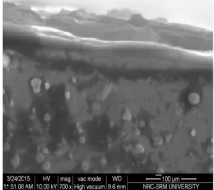
(Ø25mm x 15mm) was used as the substrate material. Their working faces were polished using a series of coarser to fine grade of silicon carbide emery papers and ultrasonically cleaned in acetone and ethanol, respectively. The coatings were prepared using a PVD techniques with argon (Ar) and pure nitrogen atmospheres. The composition coating TiCN with a thickness around 3.8 ±1Gm is as shown in the Figure (1). Coatings were deposited on the surface of AISI SS410 steel and the process parameters are shown in the Table (1).
Table (1): PVD coating deposition parameters. A machine used Standard Balzers (RCS)
machine
Make Oerlikon Balzers, Swiss
Targets power 3.5KW
Reactive gas Nitrogen
Nitrogen deposition
Pressure 3.5 Pa
Substrate bias voltage 40 V to 170 V Substrate temperature 450 °C ±10°C Coating thickness 3.8 ± 1 Gm
1 1 = + The coating surface was polished using a series of coarse to fine grade of silicon carbide emery papers. The image analyzer software of Dewinter Materials plus 1.01 based on ASTM B276 was used for calculating the porosity and PMP3 inverted metallurgical microscope used to obtain the images. As per the standard procedure, the porosity was observed to be less than 2% of the different area of the coated surface. After this wear test was followed. Figure (2) shows the chemical composition of Ti C N
coating, were observed by energy dispersive X ray analysis (EDAX). Table (2) shows the presence of Ti (50 at.%) as the main phase along with C (25 at.%) and N (25 at.%). A small amount of Cr, Mo, Fe and C is observed due to the pores present in the coating.
Figure (1) : SEM micrograph of cross‐section of worn TiCN coated die segment.
!"#$ !% & Table (2): Chemical composition of the substrate
and coating.
Composition
(at. %) P Mn C Cr S Si Ti N
Material (SS410) 1.0 % 1.0 % 0.15 % 11.5 13.5 % 0.03 % 1.0 %
Ti C N
Coated 25% 50%
25 %
1 2 + Figure (3) shows the
schematic line drawing of the ball cratering wear. The coated substrate was clamped on to a platform and fixed to the arm. This arm was rotated, around its hinge until the coated substrate were pressed against a high carbon steel ball (diameter 25 mm) rotating at 150 revs/minute. The tester has an accurate control of both the normal load and ball sliding speed. In this testing standard ASTM G77 is used as shown in Table (3). The dry sliding abrasive wear test was conducted on the AISI SS410 and Ti C N coated against high carbon steel ball. After testing to observe the worn surface by SEM. Before the experiment, the surfaces of coated and uncoated were thoroughly cleaned with ethanol. All the wear test was performed at the room temperature having relative humidity 60%. These tests were carried out at different load, constant sliding distance and sliding speed conditions. Here we varied the load at 2N (0.203 Kgf), 3N (0.305 Kgf) and 4N (0.407 Kgf) through a total sliding distance 353.43 m with a constant sliding speed of 0.3927 ms1. The weight loss measuring instrument precision value is 0.0001. Wear rate can be determined by using this equation (1).
> ? $@. : @1%;@. $.%
where M1 – Total Mass wt. Of before the test. M2 – Total Mass wt. Of after the test.
Figure (3): Schematic diagram of micro –scale abrasion tester.
Table (3): Micro‐scale abrasion test parameters.
Substrate
1.Uncoated specimen, roughness Ra=0.67 Gm,
2. Ti C N coated specimen, Surface roughness Ra= 0.785 Gm,
Sphere Ball Material
High Carbon steel, Ball diameter
25 mm, Surface roughness
Ra=0.068 Gm, Hardness 750 VHN at 100 g load
Sliding
Speed 150 rev/minute
Load 2N (0.203 Kgf), 3N(0.305 Kgf) and 4N(0.407 Kgf)
Total sliding distance
353.43 m
Condition Metal to Metal Point contact, No slurry
2 A +
2 . @ + The Vickers hardness
indenture (HV 10 Kg) was used to determine the hardness of the different location of the coated substrate and uncoated substrate. After examination, the average hardness value (337 HV) was observed in Ti C N coating and minimum hardness value (183 HV) was found in uncoated specimen is as shown in the Figure (4). The higher hardness and possibly harder wear debris. The coating has lower porosity and very dense structure. In this coated substrate has good wear resistance because of the absence of grain boundaries. Elastic modulus and hardness were determined using the procedure described in /.5 .60.
!"#$ !% &
2 1 B + The co efficient of
friction for the uncoated and coated substrate at the different loads is illustrated in Figure (5). It can be noted that the coefficient of friction initially decreases and then increases with the increase in the number of cycles. At applied load 2N, the co efficient of friction does not show the asymptotic behavior by increasing the number of cycles within the test duration is as shown in the Figure (5a). For the applied 3N load the friction co efficient increases with the applied load exhibits from Figure (5b), where for the 4N load the co efficient of friction decreases with increase in load as shown in Figure (5c). Finally the lowest coefficient of friction is observed from the 2N and 4N load. In contrast, the Ti C N film has the lowest friction co efficient at the lowest applied 2N.
Figure (5): The co efficient of friction of uncoated and coated films at different applied loads : (a) applied load = 2N, (b) applied load = 3N and (c) applied load = 4N.
2 2 > : Figure (6a) shows the
mass loss for the uncoated and coated substrate. In the different load condition, the coating shows comparatively less wear than the uncoated specimen. The mass loss volume gradually increases with increase the load. The wear performance is nearly 80% 90% greater than that of the uncoated substrate of a 2N and 4N applied load. But in 3N applied load shows 25% 30%, respectively than the wear performance of the uncoated substrate. Thus, above this 2N and 4N applied load gives the best performance and wear resistance than the uncoated substrate.
!"#$ !% &
Figure (6b): Total wear of High carbon steel ball and Ti C N coated at different loads. When Ti C N coated substrate sliding against high carbon steel balls, the behavior of the material was highly prejudiced by the differences in hardness between the ball and the coating. Against Ti C N the wear rate was computed at the various loads of 2N, 3N and 4N for the total sliding distance 353.43 m at a constant sliding speed of 0.3927 m/s is as shown in the Figure (6b). In this stage the high carbon steel ball was severely worn by coatings with high hardness.
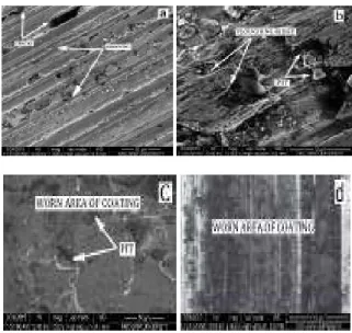
2 3 ' @ + Figure (7) shows the
microscope image of the uncoated and coated substrate after ball cratering wear test. In Figure (7a and b) shows the abrasive marks, pits, cracks and wear tracks on the uncoated substrate. A few deep grooving and ploughing was observed during the test. The material loss is based on the hardness of the substrate. The SEM image of the Ti C N coating with different load with a sliding distance of 353.43 m is as shown in the Figure (7c and d). The more grooving region, pits and cavities with Ti C N particles were observed on the worn surface of the high carbon steel ball. Final result shows hard Ti C N coated particles viewing of the worn surface. The occurrence of wear is attributed to the four wear mechanisms adhesion, abrasion, surface fatigue and tribochemical reaction /.70.
Figure (7): SEM images of the worn surface produced by ball cratering abrasive wear testing machine of (a) (b) are uncoated and (c) (d) are Ti C N coated
3 +
1. The co efficient of friction at maximum load is governed by the roughness of the coated surface.
2. The total wear decreased with the hardness of investigating film in the present work. Total wear increases with applied load of the abrasive wear test in the Newton load range.
3. Coating thickness is an important character in the tribological behavior because of the coating has very lower porosity and very dense structure.
4. The more grooving region, pits, ploughing ridge and cavities with Ti C N composite particles were found on the worn surface of the stainless steel AISI 410. This result shows off hard Ti C N coated particles viewing of the worn surface.
!"#$ !% &
* + The authors would like to thank Oerlikon coating service, Chennai, India to provide the Ti C N coating. The authors would like to thank Mr. Vetrivel and Mr. Rajesh, Professional Lab Assistants in Anna University, Chennai to support for the Micro Abrasive wear test. The authors are thankful to the reviewer for providing their useful comments, suggestions and guidelines during the course of revision to improve the technical quality of the present paper.
+
. K. Nakayama, Y. Yasutake, M. Takiguchi, S. Furuhamas, Effect of piston skirt fricition of a gasoline engine, SAE paper (1997) 970839.
1 A. Gangopadhyay, Development of Piston Ring Cylinder Bore Wear Model (2000), SAE technical paper No.2000 01 1788.
2 L. L. Ting, “A Review of present information on piston ring tribology’’, (1985), SAE Paper 852355.
3 S. B. Hill and B. A. Newman, “Piston rings designs for reduced friction’’, (1984), SAE Paper 841222.
4 L. Fedrizzi, S. Rossi, R. Cristel, P. L. Bonora, Elect. Chem. Acta, 49 (2004) 2803 – 2814.
5 Harpreet Singh, D. Puri and S. Prakash, Anti. Corros. Method Mater. 52/2 (2005) 84 – 95.
6 O. O. Ajayi, J. G. Hersgerger, J. Zhang, H. Yoon, G. Fenske, Microstructural evolution during scuffing of hardened 4340 steel Implication for scuffing mechanism, Tribology International, 38 (2005) 277 282.
7 Y. Z. Lee, K. C. Ludema, The shared load wear model in lubricated sliding: Scuffing criteria and wear coefficients, Wear 138 (1990) 13 22.
8 L. A. Dobrzanski, K. Lukaszkowiez, A. Zarychta, L. Cunha, J. Mater. Processing Technol. 164 165 (2005) 816 821.
.9 L. Cunha, M. Andritschky, L. Rebouta , K. Pischow, Surf. Coat. Technol. 116 119 (1999) 1152 – 1160.
.. W. Schintlmeister, O. Pacher, J. Vac. Sci. Technol. 12 (1975) 743.
.1 Yun Ha Yoo, Diem Phong Le, Jung Gu Kim, Sun Kyu Kim, Pham Van Vinh. Thin Solid Films 516 (2008) 3544 3548.
.2 Xing zhao Ding, A. L. K. Tan, X. T. Zeng, C. Wang, T. Yue, C. Q. Sun. Thin Solid Films 516 (2008) 5716 5720.
.3 J. E. Kelley, J. J. Stiglich Jr., G. L. Sheldon, “Methods of characterization of tribological properties of coatings”, Surf. Mod. Tech.(1988) 169 187
.4 J. A. Williams, A. M. Hyncica, “Mechanisms of abrasive wear in lubricated contacts”, Wear 152/1 (1992) 57 ‐ 74.
.5 W. C. Oliver and G. M. Pharr, “Improved technique for determining hardness and elastic modulus using load and displacement sensing indentation experiments”, J. Mater. Res.7/6 (1992) 1564 1580.
.6 L. Shan, Y. Wang, J. Li, H. Li, L. X. Wu, J. Chen, “Tribological behaviours of PVD TiN and TiCN coatings in artificial seawater”, Surface & Coatings Technology 226 (2013) 40 – 50.
.7 M. A. Chowdhury, D. M. Nuruzzaman, A. H. Mia, M. L. Rahaman, “Friction coefficient of different material pairs under different normal loads and sliding velocities”, Tribology in Industry 34/1 (2012) 18 ‐ 23.
.8 M. S. Priyan, P. Hariharan, “Abrasive Wear Modes in Ball‐Cratering Test Conducted on Fe73Si15 Ni10Cr2 Alloy Deposited Specimen”, Tribology in Industry 36/1 (2014) 97 ‐ 106.
19 B. Podgornik, J. Vižintin, O. Wänstrand, M. Larsson, S. Hogmark, “Wear and friction behaviour of duplex treated AISI 4140 steel”, Surface & Coatings Technology 120 121(1999) 502 – 508.
!"#$ !% &
11 J. C. A. Batista, C. Godoy, G. Pintaúde, A. Sinatora, A. Matthews, “An Approach to elucidate the different response of PVD coatings in different tribological tests”, Surface & Coatings Technology 174 175 (2003) 891 898.
12 C. Donnet, A. Erdemir, “Historical developments and new trends in tribological and solid lubricant coatings”, Surface & Coatings Technology 180 181 (2004) 76 – 84.
13 M. Wieland, M. Merklein, “Wear behavior of uncoated and coated tools under complex loading conditions”, Tribology in Industry 34/1 (2012) 11 ‐ 17.
14 L. Shan, Y. Wang, J. Li, H. Li, L. X. Wu, J. Chen, “Tribological behaviours of PVD TiN and TiCN coatings in artificial seawater”, Surface & Coatings Technology 226 (2013) 40 – 50.
*****