ISSN 1517-7076 artigo 11734, pp.656-665, 2016
Corresponding Author: Stephen Bernard S Received on: 25/09/2015 Accepted on: 17/05/2016
10.1590/S1517-707620160003.0063
Effect of Rockwool and Steel fiber on
the Friction Performance of
Brake Lining Materials
Stephen Bernard S1, Jayakumari L S 1
1
Department of Rubber and Plastics Technology, Madras Institute of Technology, Chennai, TamilNadu, India, +91-9444643685, e-mail: [email protected]
ABSTRACT
Wear resistance and Frictional stability are key performance requirements for brake lining. Automotive brake linings are usually made of various ingredients such as binder, filler, friction modifiers and reinforcement. Rockwool is a mineral fiber and steel fiber is a metallic fiber. In this work reinforcement fibers used are both the mineral and metallic fibers with six different composition prepared and tested. The result shows that me-tallic fibers should be high compared to mineral fiber for best frictional performance and wear resistance. Friction-wear properties of the reinforced samples were investigated on the cast iron disc as a counterpart using a pin on disc wear tester. The investigation confirmed that the sample with increase in steel fiber (4%, 8% and 12%) improves the wear resistance. On the other hand specimen with high content of Rockwool fiber forms an improper ratio among the other ingredients. The SEM images of the sample indicated that an in-crease in steel fiber higher than 12% content resulted in adhesive wear.Analysis of the experimental result shows that the sample with 12% steel fiber and 8% Rockwool fiber exhibited the optimum friction-wear be-havior. Finally the effect of environment on the composites was investigated in water, salt water and oil. Keywords: Brakes, rolling friction, steel fibre, rockwool fibre, EDS, SEM
1. INTRODUCTION
The essential component in a braking system are brake drum (rotating part) and brake lining which is the stationary part to press against the brake drum to slow or stop the rotation [1]. Brake linings are designed to withstand stable, humidity, wear and reliable friction force [2]. Brake friction materials have evolved signifi-cantly over the years. They have gone from asbestos to organic to semi-metallic formulations. Each of these materials has proven to have advantages and disadvantages regarding environmental friendliness, wear, noise and stopping capability.
Reinforcing fibers are included in the brake lining to maintain the strength, thermal stability and fric-tion properties [3,4]. Fibers in brake lining determine wear stabilizafric-tion, wear minimizafric-tion and fricfric-tion op-timization under a dynamic set of operating variables such as braking force, sliding speed, braking duration and braking temperature [5,6]. (commercial brake lining contains 16-20% of reinforcing fibers [6]).
Along with fibers, binders, fillers, lubricants and abrasive particles are added to improve the friction properties. Among many ingredients, the fiber plays a crucial role in determining the friction properties. Usu-ally brake lining consists of 5–25 vol% of reinforcing fibrous ingredient which influences the brake achievement [7]. While braking, pads are in direct contact with the braking drum and transfer the pressure of 1.2 MPa during soft braking and 10 MPa in extreme condition. steel and copper fibers have a higher strength to withstand the function of direct and sliding contact of the brake drum. The main drawback is that copper decreases the coefficient of friction [8-10].
materi-657 al due to their inherent thermal stability. Cashew friction dust is used to improve friction stability at elevated temperature and it is the organic ingredient which helps to remove the pyrolyzed friction film at the friction interface [10]. Graphite is extremely resistant to heat and highly chemically inert in contact with almost any other material. It is used in brake lining with the need to substitute for asbestos. Antimony trisulfide will ignite at higher temperature and does not react with water at room temperature [13].
Designing friction brake material is often based on experience or a trial and error method to make a new formulation. It has long been claimed as a problem of multistage optimization right from selection of ingredients to processing till reaching at appropriate set of performance criteria [13-17]. In our previous work, there was clear and substantial studied were carried on the effect of Cardanol in phenolic resin binder [18].
A limited number of studies investigating the effect of reinforcement fibers in brake pad materials are available in the literature and complete analysis of the keyrole of reinforcement fiber is seldom found. In this experiment steel and rockwool fiber increased up to 20% by increasing 4, 8 ,12, 16 and 20%.
2. EXPERIMENTAL WORK
2.1 Materials
Rock wool fiber (B M marketing and trading pvt. ltd., Chennai), Steel fiber (Ryan international, Mumbai), Cardanol and cashew dust (Satya Cashew chemicals pvt. ltd., Chennai), Phenol formaldehyde (Esterkote pvt. ltd., chennai) and Calcium carbonate, antimony trisulfide, graphite, calcium silicate, alumina and silicon (All from metro scientific company, chennai) were used during investigation.
2.2 Sample Preparation
All the ingredients were weighed using an analytical balance instrument and mixed using a blender (electron EBR 100) for 6 min at 10000 rpm in room temperature (300 C). Fibers (Steel fibers and Rock wool fiber) were added initially followed by the required quantity of filler (calcium carbonate), abrassive (alumina), lubricants (antimony trisulfide and graphite) and friction modifiers (vermiculate, calcium silicate and cashew dust) added simultaneously. Finally binder material was added [10]. Table 1 shows the ingredients of the friction material investigated in this work. For analyzing hardness, bulk density, compressibility, porosity and wear properties of the specimen, two different molds (size: 150 x 150 x 3 mm and φ5 x 32 mm) were used for pressing.
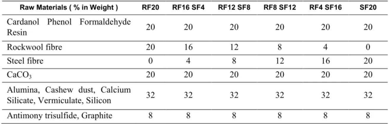
Table 1: The ingredients of the friction material investigated in this work
Raw Materials ( % in Weight ) RF20 RF16 SF4 RF12 SF8 RF8 SF12 RF4 SF16 SF20
Cardanol Phenol Formaldehyde
Resin 20 20 20 20 20 20
Rockwool fibre 20 16 12 8 4 0
Steel fibre 0 4 8 12 16 20
CaCO3 20 20 20 20 20 20
Alumina, Cashew dust, Calcium
Silicate, Vermiculate, Silicon 32 32 32 32 32 32
Antimony trisulfide, Graphite 8 8 8 8 8 8
The die was preheated to 180 °C and pressure of 160 kg/cm2 was applied over a mixture for a molding time of 6 min. Molding involves several stages: initial molding, elastic–plastic deformation and particle fracture or fragmentation [14]. During the initial stage, rearrangement of powder particles, which leads to the filling of large voids and the break up of particle bridges. In the elastic–plastic stage, the applied pressure is further increased and plastic deformation occurs locally at the inter particle contact points. In the final stage of molding, plastic deformation becomes widespread, accompanied by shearing, generation of new oxide-free surfaces, cold welding of contacting surfaces and accompanied by reduction in porosity.
658 (Dimension: 150 x 150 x 3 mm and φ5 x 32 mm) in a preheated furnace for 4 hrs. Because the particles of a material are joined together and gradually reducing the volume of pore space among them, enhances curing uniformity, reduces thermal expansion
2.3 Test and analysis
Specimens were sectioned and examined using scanning electron microscope (SEM) model EVO MA15 to determine mixing of friction materials. Prior to SEM evaluation, the specimens are coated with gold using plasma sputtering apparatus Edwards sputter coater model S150B. For the energy dispersive X-ray analysis of the specimen, an Oxford instruments Nanoanalysis INCA Energy 250 Microanalysis system (EDS) was used. The environmental effect of the friction material were determined at room temperature and measured by ASTM D 570-77 standard with water, salt water and SAE 20w-40. Using Rockwell hardness tester hardness of friction material specimen was measured. Bulk density was measured by the water dis-placement technique using the standard SAE J380. Compressibility measurement was performed using a compression tester and it is obtained from the slope of the height change as a function of applied pressure. The crosshead speed of the machine was kept at 0.5 mm/min [18].
A material is tested using pin on disc apparatus which provides automatic acquisition of friction coef-ficient and wear measurements. It gives stable coefcoef-ficient of friction once running in phase is achieved. Wear test was conducted using DUCOM wear and friction monitor - TR 20 with grey cast iron as the counter part with a diameter of 120 mm. All the testing procedures were operated by a WinDucom data acquisi-tion system on a computer using the ASTM G-99 standard. The size of a single composite material is 8 mm diameter and a length of 32 mm. The disc was ground to a smooth surface finish and renewed for each test. The samples were placed on the wear disc and the sliding wear tests were carried out at various time and speed. The test was conducted in a load range of 20 N at a sliding velocity of 2 - 4 m/s and at sliding distance of 6.3 km. For each specimen the testing time is 2100 s by varying the speed (300, 500, 700 RPM) with re-spect to 700 s. After each test, the specimens were removed, cleaned in acetone and weighed with an elec-tronic balance within an accuracy of 0.1 mg. The friction force (F) was continuously monitored during the wear test for determining the coefficient of friction (μ). The friction force was measured for each pass and then averaged over the total number of passes for each wear test.
3. RESULTS AND DICUSSIONS
3.1 Properties of Composites
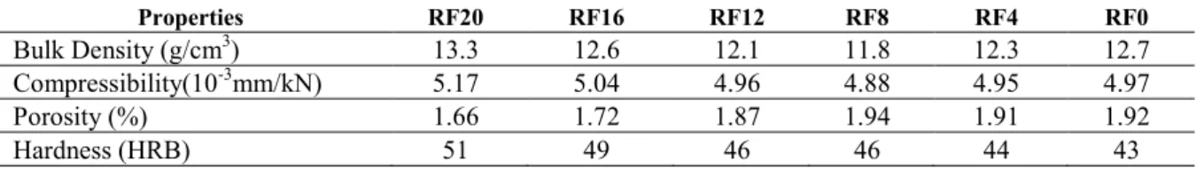
Table 2: Properties of the specimen
Properties RF20 RF16 RF12 RF8 RF4 RF0
Bulk Density (g/cm3) 13.3 12.6 12.1 11.8 12.3 12.7
Compressibility(10-3mm/kN) 5.17 5.04 4.96 4.88 4.95 4.97
Porosity (%) 1.66 1.72 1.87 1.94 1.91 1.92
Hardness (HRB) 51 49 46 46 44 43
As seen from the table 2 most of the property such as bulk density, compressibility and porosity (RF20 > RF16 > RF12 > RF0 > RF4 > RF8) decreased slightly and then increased, which is in tune to the literature range [24]. This is due to the reduction of rockwool fiber and increase of metallic fibers. Brake roughness is dependent on porosity [22]. In RF4 and RF0 due to lower content of rockwool fiber porosity decreases. Higher volume of metallic fiber decreases the hardness of the specimen.
3.2 Wear
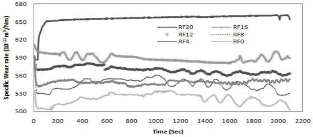
The specific wear rate of the composite as a function of time is shown in figure 1. It was observed that with the progressive increase in the steel fiber content consistently reduces the weight loss and thickness loss of the composite indicating that presence of steel fiber is responsible for wear in the friction material. For in-stant, highest wear rates were observed for RF20. It indicates that the surplus rockwool fiber appears which form a improper ratios among the other ingredients. Wear is dependent [19] on hardness, thermal stability of the ingredient and integrity of the composite that is mainly determined by the effectiveness of the reinforce-ment.
659 drum along the sliding direction [20] and also a portion of compressed layer of lining material is eventually established on the cast iron counterface, forming a film of glaze and some wear particle are produced during the initial bedding in process [21]. Meanwhile RF12 SF8 and RF8 SF12 showed the best wear performance suggesting this type of reinforced sample has longer life. This may be due to metal chips is nearly equal to the mineral fibre which supresses the wear and enhances frictional performances. The improved wear re-sistance of the friction material is attributed to the inherent wear rere-sistance of steel with rockwool fibre.
Figure 1: Effect of varying fiber content on Wear properties
Figure 2: Average specific wear rate as a function of varying fiber content
The average specific wear rate of the specimen with different composition of steel and rockwool fibre is shown in figure 2. From the result it is clear that the highest wear resistance was obtained for SF20 but the friction coefficient decreases for the same specimen. In particular the average specific wear rate of the RF20 specimen was about 10.3% higher than the RF16 SF4, which indicates that the fade resistance of the material decreased [19]. The specimen with steel fibre 12% produced a wear resistance high with a good friction co-efficient values. This is certainly an interesting result and further investigation is in progress to understand the interaction with other ingredients.
3.3. Friction stability
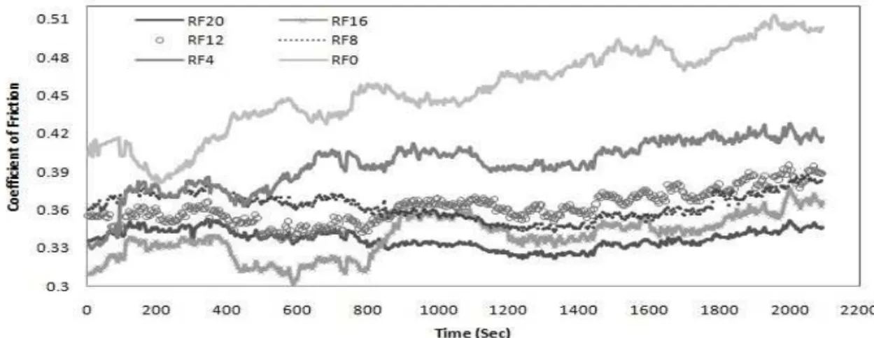
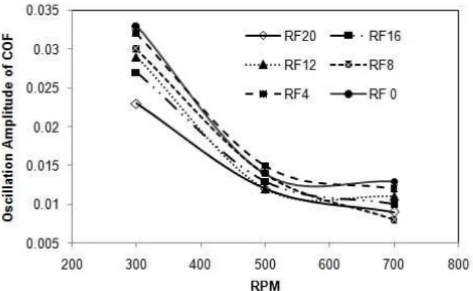
660 SF20 RF0 showed a continous increase in the friction coefficient between 900 and 1600s [20] is often associated with the adhesion of metal chips in the brake lining to the friction surface of the cast iron disc. Except RF4 SF16 and SF20, the COF decreased approximately 8% during the rotational speed of the counter disc increased by 200 rpm. This suggests that the increase in rotational speed of the counterpart affect the friction level for the same composition of the reinforcement [23].
RF16 SF4 showed the sudden loss of friction coefficient in the rotational speed range of 1000-1300 rpm. The drastic decrease of friction coefficient indicates that the rockwool fibre are detached from the bind-er resin during sliding at highbind-er rotational speed [24]. COF decreased at 300 rpm by increasing steel fibbind-er content 8%; however, in the later stage i.e., at 500 rpm and 700rpm COF increased. From the figure 4 it is clear that friction coefficient decreases with an increase of rockwool fibre content. This cause a lowering of brake force in the case of higher braking force, therefore,it is undesirable result. In beginning sudden de-crease of COF is observed for SF20 due to test conducted before a stable friction layer was developed [25]. The oscillation of COF was higher in this time period.
Figure 3: Effect of varying fiber content on Coefficient of Friction
Figure 4: [COF]avg and [COF]max - [COF]min as a function of varying fiber content
661 Figure 5: Effect of oscillation amplitude of COF as a function of RPM
3.4 Microstructural Characteristics
662 The wear surface of the sample after the friction test were observed using an SEM with energy dispersive X-ray analysis is shown in figure 6 (a-f). The SEM images show when the steel fibre particles were less in con-tent, they were easily released from the lining surface. On the other hand when the steel fibre content is in-creased, the fibres were firmly bound in the resin and tended to abrade the disc, resulting in less wear amount in lining surface. Interesting aspect for RF8 SF12 and RF12 SF8 lining surface were not tending to damage even though the rotational speed of the disc is increased.
The thick friction layer is developed on the surface of RF8 SF12. It indicates that the friction layer covering the friction surface diminishes the abrasive effect of the glassy phase by eliminating the sharp edges of the composite and smoothening the friction surface [24].
The figure shows larger contact plateaus in the case of specimen RF12 SF8 while transient patches are observed in RF8 SF12. The contact plateaus form the real contact area in developing friction forces. The primary contact plateaus are formed due to the low removal rate of wear resistant RF12 specimen. The con-tact plateaus are formed due to wear debris and a gap between the specimen and the cast iron disc. The di-mensions and composition of those plateaus includes a vital influence on the frictional stability of the speci-men [26]. These imperfect contact areas enable smaller particles to pass between plateaus. In RF12, second-ary contact plateaus are formed by thin solid film generated as a consequence of sliding contact that is ad-hered on its parent worn surface with sintered debris. When the applied pressure is reduced large portions of these solid film areas peel off in flakes [28]. It is seen that the smaller micro voids occurred in the sample having larger rockwool fibre. The larger size micro voids are observed in the increase of steel fibre particles after the friction test. This is due to the loosening of the metallic particles during the friction and it indicates that metal-component coherent surface is larger, friction and wear will be increased [27].
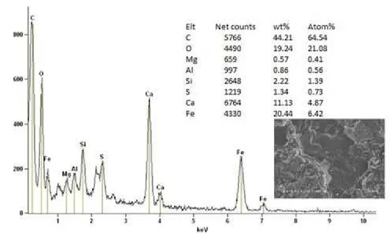
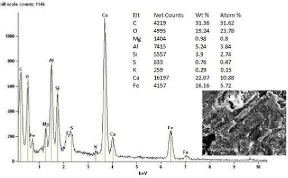
Figure 7 shows the EDS analysis result taken from the black areas of the RF8 SF12 specimen while figure 8 shows the EDS analysis result taken from white areas of the same specimen. From both analyses it is observed that all the chemical elements are present in black and white areas except potassium which is not related to steel and rockwool fibres. It indicates that steel and rockwool fibres are homogeneously mixed throughout the specimen.
663 Figure 8: EDS analysis result taken from the white areas of the R8 specimen
3.5 Environmental effect
Table 3: The Variation of weight for each sample in water, salt water and oil
Specimen Water
wt (%)
Salt Water wt (%)
Oil wt (%)
RF20 3.284 5.371 6.197
RF16 2.943 4.176 7.231
RF12 3.782 4.97 5.316
RF8 3.146 5.138 5.684
RF4 2.374 4.376 6.236
RF0 2.828 4.241 6.197
It is seen that variation of mass for each sample has been obtained for different environmental conditions after the wear test is tabulated in table 3. COF value is higher for the specimen SF20, though there is smaller absorption of water in this specimen compared to other specimen. It is clearly noted that when the quantity of rockwool fibre is high, it increases the absorption of water, salt water and oil. It is mostly related to the per-meability of fibre and a lower degree of resistance to all naturally occurring chemical, biological and envi-ronmental factors. For all specimen absorption of oil is high compared to water and salt water. RF8 SF12 with absorption of oil has only 9% increase compared to salt water. Environmental test reveals some more interesting phenomenon that reinforcing fibres were not influenced absorption of oil much higher as like oth-er ingredients.
4. CONCLUSION
The effect of reinforcement on the friction characteristics, mechanical properties and its morphology were investigated using six friction materials. Friction characteristic such as wear resistance, coefficient of friction, oscillation amplitude of COF were measured by using win ducom friction tester. The conclusion from this work can be summarized as follows.
1. The friction coefficient is dependent on both steel and rock wool fiber. More than 12% of steel fiber increases the value of COF higher than 0.45 which affects the performance of braking.
664 RF0 due to large content of steel fiber. Hardness decreases consistently when a rockwool fiber is smaller in content.
3. On the other hand wear resistance has been observed to decrease consistently with an increase in rock wool fiber. The specimen with steel fiber 12% produced a high wear resistance with a good friction co-efficient values.
4. Addition of rock wool fiber may lead to smaller size microvoids, however larger size microvoid strongly depend on increase of steel fiber. Larger contact plateaus are formed in RF12 while transient patches are observed in RF8.
The result summarized above suggest steel and rockwool fibre combination for the best tribological properties used for brake lining application are 12% steel fibre and 8% rockwool fibre which could potential-ly lead to an optmized overall performance.
5. ACKNOWLEDGEMENTS
Author gratefully acknowledge the support of machine design section, IIT Madras for allowed to use DU-COM wear and friction monitor - TR 20 instrument and Madras Institute of Technology for their help in making friction materials and conduct testing.
6. BIBLIOGRAFIA
[1] HEE, K.W., FILIP P. “Performance of ceramic enhanced phenolic matrix brake lining materials for au-tomotive brake linings”, Wear, v. 259, pp. 1088–1096, 2005.
[2] ARNAB, GANGULY, RAJI, GEORGE, “Asbestos free friction composition for brake linings”, Bulletin material science, v. 31, pp. 19-22, 2008.
[3] MORSHED, M.M., HASEEB, A.S.M.A., “Physical and chemical characteristics of commercially availa-ble brake shoe lining materials: a comparative study”, Journal of Materials Processing Technology, v.156-156, pp. 1422–1427, 2004.
[4] SHARIFAH, H. A., MARTIN, P. A., “The effect of alkalization and fibre alignment on the mechanical and thermal properties of kenaf and hemp bast fibre composites: part 2 – cashew nut shell liquid matrix”,
Composites Science and Technology, v.64, pp. 1231-1238, 2004.
[5] ARCHANA, D., DEEPAK , S., “Studies on the blends of cardanol-based epoxidized navolac resin and CTPB”, European Polymer Journal, v.43, pp. 2422-2432, 2007.
[6] PAPADOPOULOU, E., CHRISSAFIS, K., “Thermal study of phenol formaldehyde resin modified with cashew nut shell liquid”, Thermochimica Acta, v. 512, pp. 105-109, 2011.
[7] MWAIKAMBO, L.Y., ANSELL, M.P., “Hemp fibre reinforced cashew nut shell liquid composites”,
Composites Science and Technology, v.63, pp. 1297-1305, 2003.
[8] RYOHEI, I., HOZUMI, T., HIROSHI, U., et al, “Synthesis and curing behaviors of a crosslinkable
poly-mer from cashew nut shell liquid”, Polymer, v. 43, pp. 3475-3481, 2002.
[9] MINAKSHI, S., RAI, JSP., DEEPAK, S. “Process modeling,optimization and analysis of esterification reaction of cashew nut shell liquid (cnsl)-derived epoxy resin using response surface methodology”, Journal of Hazardous Materials, v. 185, pp. 1198-1204, 2011.
[10] UEXKULL , O.V., SKERFVING, S., DOYLE, R. “Antimony in brake pads-a carcinogenic component? ”, Journal of Cleaner Production, v. 13, pp. 19-31, 2005.
[11] AMAR, PATNAIK., MUKESH, K., BHABANI, K.S., et al, “Performance sensitivity of hybrid phenolic composites in friction braking: Effect of ceramic and aramid fibre combination”, Wear, v. 269, pp. 891-899, 2010.
[12] JANG, H., LEE, J.S., FASH, J.W., “Compositional effects of the brake friction material on creep groan phenomena”, Wear, v. 251, pp. 1477-1483, 2001.
[13] CHO, M.H., KIM, S.J., BASCH, R.H., et al., “Tribological study of gray cast iron with automotive brake linings: The effect of rotor microstructure”, Tribology International, v. 36, pp. 537–545, 2003.
[14] GURUNATH, P.V., BIJWE, J., “Friction and wear studies on brake-pad materials based on newly de-veloped resin”, Wear, v. 263, pp. 1212–1219, 2007.
665 [16] CHO, M.H., KIM, SEONG, J., KIM, D. “Effects of ingredients on tribological characteristics of a brake lining: an experimental case study”, Wear, v. 258, pp. 1682–1687, 2005.
[17] BIJWE, J., ARANGANATHAN, N., SHARMA, S. “Nano-abrasives in friction materials-influence on tribologicalproperties”, Wear, v. 296, pp. 693–701, 2012.
[18] STEPHEN BERNARD, S., JAYAKUMARI, L.S., “Effect of the Properties of Natural Resin Binder in a High Friction Composite Material”, Polímeros, v. 24, pp. 149-152, 2014.
[19] KIM, Y. C., CHO, M. H., KIM, S. J. et al, “The effect of phenolic resin, potassium titanate, and CNSL
on the tribological properties of brake friction materials", Wear, v.264, pp. 204–210, 2008.
[20] EL-TAYEB, N.S.M., LIEW, K.W., “Effect of water spray on friction and wear behaviour of noncom-mercial and comnoncom-mercial brake pad maerials”, Journal of Materials Processing Technology, v. 208, pp. 135-144, 2008.
[21] CHO, K.H., CHO, M.H., KIM, S.J., et al, “Tribological properties of Potassium Titanate in the brake
friction materials; Morphological effects”, Tribology Letters, v.32, pp. 59-66, 2008.
[22] MATEJKA, V., LU, Y., MATEJKOVA, P., et al., “Possible stibnite transformation at the friction sur-face of the semi-metallic friction composites designed for brake linings”, Applied Surface Science, v. 258, pp. 1862-1868, 2011.
[23] MUTLU O. E., FINDIK, F., “Tribological properties of some phenolic composites suggested for auto-motive brakes”, Tribology International, v. 39, pp. 317–325, 2006.
[24] BLAU, P.J., BRIAN, C. J., “Wear of truck brake lining materials using three different test methods”,
Wear, v. 259, pp. 1022–1030, 2005.
[25] BOZ, M., KURT, A. “The effect of Al2O3 on the friction performance of automotive brake friction ma-terials”, Tribology International, v. 40, pp. 1161–1169, 2007.
[26] DAVIM J. P., CARDOSO, R. “Tribological Behaviour of the Composite PEEK-Cf30 at dry Sliding against steel using statistical techniques”, Material And Design, v. 27, pp. 338-342, 2006.
[27] CHO, K.H., JANG, H., HONG, Y.S., et al., “The size effect of zircon particles on the friction character-istics of brake lining materials”, Wear, v. 264, pp. 291-297, 2008.