Efects of Diferent Plasma Nitrided Layers on the Tribological Performance of DLC
Coatings
Pedro Henrique Teshima Shiogaa*, Cristiano Bindera, Gisele Hammesa, Aloisio Nelmo Kleina, Jose
Daniel Biasoli de Melloa
Received: August 10, 2015; Revised: July 19, 2016; Accepted: August 11, 2016
When multifunctional surface engineering processes that combine purpose-oriented phases are
applied to soft substrates, a combination of high wear resistance, high load support and low coeicients of friction can be achieved. In this study, the efects of diferent nitrided layers on the tribological behaviour of a diamond-like carbon (DLC) ilm deposited on a SAE 1040 steel were investigated. The nitriding was carried out under diferent temperatures and gas mixtures to create three distinct nitrided layers: two compound layers with predominant ε and γ’ phases and a difusion layer. All of the surfaces were then coated with DLC deposited via plasma-enhanced chemical vapour deposition (PECVD). The tribological tests indicated that the best performance was achieved for a speciic combination of hardness, surface roughness and nitride type. The best load-bearing capacity between the DLC coating and the soft substrate was achieved when the nitrided layer was primarily a difusion layer.
Keywords: DLC, Nitriding, Roughness, Friction, Adhesion
* e-mail: [email protected]
1. Introduction
Diamond-like carbon (DLC) encompasses a family of coatings with widespread use in tribological applications
due to their low coeicients of friction in metal-DLC pairs
(usually 0.1<µ<0.2, but values as low as 0.01 have been reported)1–3, which are associated with extremely low wear
rates (10-9-10-10 mm3/Nm)3,4.
Hard solid lubricant coatings have found success in many applications, particularly those involving pure elements such as silicon and advanced materials5–8. Other systems have used
relatively hard substrates, such as hardened steels9; however
large-volume production industries utilise soft, simple and
inexpensive materials as substrates for DLC coatings, which
require multifunctional surfaces for mechanical support and chemical adhesion.
One solution involves progressively increasing the surface hardness and creating a mechanical support by
plasma nitriding, a difusive thermochemical treatment
that increases the surface hardness of steels and metallic alloys10,11. In contrast to other surface treatments such
as gas nitriding, salt bath nitriding, carbonitriding, and nitrocarburising12–15, in plasma nitriding temperature is not
dependent of a conventional heat source. Plasma energy is the heat source and process temperature can be adjusted with
plasma voltage and pressure in addition to an external heat source. Thus, producing minimum dimensional distortions
in the treated parts, which are normally caused by stress
relief if temperatures of up to 600°C are used10. Therefore,
plasma nitriding is an interesting technique used to produce multi-layered coatings for components employed in high-precision applications. Moreover, this process generates little waste, requires few consumables, is easy to control and compatible with the levels required by industry10,16 but
mostly the same equipment can be used to carry out nitriding and DLC-coating17–19
The resulting coating is composed of two main layers: an external compound layer with the highest hardness values and a difusion layer with a hardness that decreases toward
the core of the material. During plasma nitriding, this nitrided layer structure is achieved by accelerating nitrogen ions against the sample surface, cleaning the surface, heating
the workpiece, and providing active nitrogen that difuses into the matrix20,21. Unfortunately, this bombardment also
modiies the topographical characteristics of the specimen10,
increasing the roughness to the micrometre range22,23 and
directly afecting the mechanical support of DLC8,24. Depending on the control variables applied in this
process, particularly the temperature and gas mixture, diferent nitride phases with distinct characteristics can be
stabilised21. Previous studies have reported surfaces with
diferent hardness proiles and case depths for diferent gas mixtures23. Another study showed that nitriding signiicantly
changes the surface roughness relying on processing
parameters. The initial roughness can also afect the case
depths of the nitrided layers25.
aLaboratório de Materiais – Labmat, Departamento de Engenharia Mecânica, Universidade Federal de
Due to the multifunctional nature of the surface, all of
these factors can signiicantly afect the adhesion of DLC, which in turn afects tribological performance.
Techniques based on indentation tests, which are
used to assess adhesion, particularly the German standard
VDI319826,27, are popular due to their simplicity and ease
of use. In these methods, the surface is indented under
standardised parameters, resulting in ilm failure. The failure is characterised through six qualitative patterns: HF1 to HF6. However, four important issues have been identiied when
using this method:
• There is a strong dependence on user interpretation,
afecting the characterisation process when the failure characteristics are similar or when diferent people are performing the classiication;
• Because only six patterns are available, the standard
categorises diferent forms and intensities of
delamination equally;
• Beyond the maximum classiication HF6, every indentation with a large delamination area is
classiied as the same pattern;
• The results of ilm cracking and delamination vary over time after introducing the indentation,
but the standard does not deine when to perform
the analysis.
Therefore, we developed this technique further, yielding an enhanced method based on the VDI3198
standard, and image analysis was proposed for assessing delamination.
In this study, the relationship between the nitriding parameters, surface roughness, coating adhesion and tribological performance were assessed. In particular, multipurpose coatings (different nitrided layers coated with DLC) were characterised by 3D surface topography analysis, indentation tests and reciprocating sliding tests.
2. Materials and methods
Three nitrided layers with diferent characteristics were
produced: one compound layer with a predominant ε phase,
one compound layer with a predominant γ’ phase and one difusion layer. These surfaces were then coated with the same DLC material. These multifunctional surfaces are referred
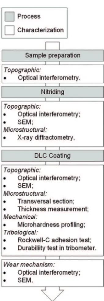
to as ε, γ’ and difusion. Figure 1 shows the processes and characterisation techniques used in this work.
The multipurpose coatings were deposited on SAE1040
carbon steel, which is a class of material commonly used in the
mechanical industry. The samples were obtained by cutting a bar of SAE1040 carbon steel; one of the lat faces was ground and mirror polished to an Sq value < 0.05 µm. The samples were subsequently nitrided in a hot wall plasma reactor under
three diferent processing conditions. These conditions were
developed based on a previous study11 and are presented in
Table 1. A plasma was produced using electrical discharge in the
Figure 1: Experimental organogram containing processing and
characterization techniques organized in chronological sequencing..
luminescent abnormal regime with a voltage of -500 V applied to the samples via a square-wave signal with a frequency of 4
kHz and a duty cycle of 62,5%.
The DLC layers were obtained via PECVD in two steps:
one involving a high silicon content for adhesion28,29and one
involving only a hydrocarbon precursor.
The nitride phases were characterised using an X-ray difractometer with Cu Kα (λ=1.5418 Å) radiation and a Bragg-Bretano geometry (40 kV - 30 mA).
The evolution of the samples’ surface topography
was monitored using optical white-light interferometry.
3D images were obtained using sample sizes of 640x480
points with a lateral resolution of 0.28 µm and a vertical
resolution of 0.1 nm. The surfaces were analysed using
the Mountains Map® software. After form removal, the
waviness was subtracted using a 25 µm cut-off, and
the surface roughness parameters were obtained. To complement the surface analysis, SEM images of the
surfaces were obtained.
The adhesion of the coatings was determined using an enhanced technique based on the German standard VDI3198, causing the ilms to fail when using a standardised Rockwell-C
indenter (diamond cone; 120o; tip radius of 0.2 mm) and a
Table 1: Nitriding parameters
Temperature (°C) Pressure (Torr) Time (h) Gas mixture (%) Expected phase
550 2 1.5 90N2-9H2-1CH4 ε
570 2 4.0 20N2-80H2 γ’
480 2 1.5 5N2-95H2 Difusion layer
Figure 2: Transversal sections of: (a) ε-phase compound layer; (b) γ’-phase compound layer; and (c) difusion layer, indicating layers
and thicknesses.
The tribological behaviour of the multipurpose coatings
(DLC+nitrided layer) was evaluated through a durability test using the method presented by de Mello and Binder30 In
this method, the sample surface is subjected to reciprocating movement under an increasing normal load until failure and with a consequent increase in friction. A tribometer with reciprocating movement (2 Hz) was used, and the initial normal load (7 N) was increased in intervals of 7
N; a counter body, speciically a sphere measuring 3 mm in diameter made of Si3N4, in an atmosphere composed of
ambient air (25°C and 60% relative humidity) were used.
3. Results and Discussion
The processing parameters presented in Table 1 produced
three types of surfaces, as demonstrated by the transversal
sections of the layers depicted in Figure 2, where layer thickness was measured. Under the irst two conditions, a homogeneous compound layer was formed. The depth of the compound on
the ε layer was approximately 6.5 µm, whereas that on the γ’
layer was approximately 4.5 µm. Noly, the growth rate of the
ε layer was considerably higher than that of the γ’ layer; even after increasing the treatment time for the γ’ layer by more
than 2.5 times the original treatment time, the formed layer was 30% thinner than the ε layer. On the difusion layer, small
non-continuous compound phase formed on the surface. The
DLC thickness was also assessed under all three conditions, which all produced 1.8 µm thick DLC.
Each of the surfaces was assessed in an X-ray difractometer,
revealing that the desired nitride phases were obtained, as
shown in the difractograms presented in Figure 3. Layer (a) of the igure exhibited a combination of the ε and γ’ phases,
with a predominance of the former. Layer (b) contained only
the γ’ phase. Layer (c) presented α-ferrite and γ’ peaks due to
the presence of small non-continuous γ’ nitride formations on the surface.
The surface hardening caused by nitriding was analysed using the proiles created via Vickers micro-indentation at 50g load, irst indentation was measured from the plan view
and further measured from the cross section with 10µm
space in between. The two compound layers presented the highest hardness (880 HV), which rapidly decayed within
20 µm to match the core hardness (300 HV). The difusion
layer had a surface hardness of 380 HV, also matching the
core hardness within 20 µm.
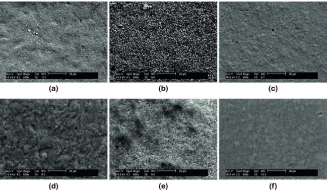
The surface development was assessed through optical interferometry and SEM images shown in Figure 4. At irst
glance, it appears that the ε and γ’ conditions generated
larger modiications, particularly the γ’ conditions. The
formation of peaks over a plateau can be observed on top
of the surface generated by the difusion conditions. When
comparing the surfaces before and after DLC coating, the
DLC appears to mimic the previous topography, except for that of the γ’ layer; the roughness over the γ’ layer appears
to have increased primarily through the formation of valleys.
These SEM images show that the gas mixture ratios clearly afected the resulting surface characteristics directly. The conditions for growing only a difusion layer are the ones that produced the smallest modiications, followed by
the conditions for the ε layer and then the γ’ layer. Under
the γ’ conditions, several electronic charging dots can be
observed, in contrast to the observations made for the
other two sets of conditions. This diference is primarily
attributed to the longer treatment time; according to Mason31,
90% of pulverised atoms return to the cathode after being
backscattered, creating the structures revealed by SEM.
Figure 3: X-ray difractograms of: (a) ε-phase predominant surface; (b) γ’-phase surface; and (c) difusion surface with small non-continuous γ’ nitride formations.
Figure 4: Top-down SEM images of nitrided and coated surfaces: (a) ε-phase surface; (b) γ’-phase surface; (c) difusion surface; (d) coated ε-phase surface; (e) coated γ’-phase surface; (f) coated difusion surface.
the previous surface under the ε and difusion conditions. In
the SEM image of the ilm produced under the γ’ conditions,
the heterogeneous formation of the coating can be observed;
regions with densiied ilm and bad formation where the previous surface occurred are apparent. Therefore, the topography and composition of the γ’ layer signiicantly
altered the deposition conditions of the DLC.
The surface root mean square roughness parameter (Sq) proves the validity of these initial observations of the development of the surfaces, as shown in Figure 5. The data
are organised based on the conditions and processing steps:
polished surface; nitrided surface; DLC-coated surface. The
nitriding process increased the roughness by at least one order of magnitude under all conditions. As observed in the projections, the ε and γ’ conditions increased the roughness
by a factor of approximately two relative to that achieved
under the difusion conditions. After coating with DLC, the
roughness of the ε and difusion layers remained unmodiied,
unlike that achieved under the γ’ conditions. Under the γ’ conditions, the mean Sq values increased.
The adhesion of the DLC ilm over the nitrided layers was characterised using a more reined version of the German standard VDI 3198. This method was developed
as a routine in an image analysis software program and
was used to quantify the area covered by ilm delamination and, subsequently, to compare the surfaces directly. The colours of the ilm and the substrate where the ilm detached could be diferentiated using a contrast tool; afterwards, the delamination area could be calculated based on the pixel
area before being converted to mm2 after subtracting the
indentation area. To assess how the delamination varied over time, the same indentation was analysed at diferent times, as shown in Figure 6. The delaminated area varied dramatically over the irst hour after indentation, growing slowly over the hours that followed. The minimum period was deined as 24 hours after indentation to measure the failure area when the variation did not exceed 1%. Samples
within this period were stored in medium vacuum and room temperature, around 20°C.
Figure 7 presents the results of the adhesion tests under
all three conditions; most of the delamination occurred on the indentation perimeter where the stress was higher32.
Figure 8 shows the delamination areas. The DLC layers on
top of the compound ε and γ’ layers exhibited the lowest
extent of delamination, whereas the extent of delamination on the difusion layer was almost twice that observed for
Figure 5: Sq roughness parameter evolution along processing steps:
polished surface; nitrided surface; and DLC-coated surface, for each
surface condition: ε-phase; γ’-phase ; and difusion.
Figure 6: Coating delamination measured by spalled area versus time after Rockwell-C indentation.
Figure 7: Top-down micrographs of Rockwell-C indentation assessing delaminated area of: (a) coated ε-phase surface; (b) coated γ’-phase surface; (c) Coated difusion surface.
remaining surrounded by uncoated areas, revealing the distinct
propagation of the delamination. On the indented coated difusion
layer, no cracks were observed, and the border was clear due to the higher deformation sustained under these conditions.
Consequently, adhesion was strongly related to the
surface conditions of the ilms, and the following factors exerted the greatest inluence:
• Roughness: Rougher surfaces were rich in peaks and valleys; stress tended to concentrate among these
variations in amplitude, and the ilm tended to crack irst34. • Layer morphology: Characteristics of the formed
layers, including thickness, yield modulus, yield
and ultimate tensile strength, afected the stress ield during and after indentation. Therefore, diferent
types of cracks and deformed regions caused distinct delamination behaviours.
• Coating homogeneity: The quality of the DLC coating was related to the topography of the nitrided surface. Depending on the characteristics, a homogeneous or heterogeneous coating could be formed, generating
diferent failure patterns.
The behaviour of the coated surfaces during durability testing is shown in Figure 10. The coeicient of friction was followed under each condition until each ilm ruptured; at
that point, an abrupt increase in the measured value was
observed. In Figure 10, the coeicient of friction is drawn
in black, whereas the stepped force is drawn in light grey; both parameters are plotted versus distance travelled.
The evolution of the coeicient of friction (COF) in the graph clearly shows that each set of conditions exhibited distinct tribological behaviours. The best tribological performance was achieved by the DLC coating over the difusion layer, exhibiting a durability of 13,000 Nm and the lowest COF (approximately 0.05). The coated ε layer was the second
best, exhibiting a durability of approximately 6,000 Nm and an initial COF of 0.125 that smoothly decreased to 0.1. The worst performance was demonstrated by the coated ’ layer; this system failed at the beginning of the test, exhibiting a durability of 600 Nm and the highest COF (0.2).
The durability results and their relationships to the adhesion
test results revealed antagonistic behaviour, as shown in
To verify that the delamination behaviour was caused by indentation, backscattered SEM images were collected for each type of layer (Figure 9). On the indented ε layer, circumferential and radial cracks can be observed on the compound layer, which tend to appear during loading and unloading, respectively33. Similarly to that on the ε layer, the
delamination on the γ’ layer occurred along the perimeter of
Figure 9: Top-down SEM images of Rockwell-C indentations on: (a) coated ε-phase surface; (b) coated γ’-phase surface; and (c) coated difusion surface, evidencing failure patterns.
Figure 8: DLC spalled area caused by Rockwell-C indentation
on: coated ε-phase, coated γ’-phase, and coated difusion surfaces.
Figure 11; both variables are presented in the same graphic. Adhesion is expressed as the inverse of the delaminated area.
Consequently, the best response for both tests is the upper
limit of the graph area; speciically, the durability should be maximised, and the delaminated area should be minimised. However, these attributes are not presented in the igure. Although the difusion layer exhibited the worst adhesion
during the indentation test, it demonstrated the highest
durability and the smallest coeicient of friction. However, the DLC over the γ’ layer showed the worst tribological
behaviour but did not show accentuated delamination, as observed under the ε conditions.
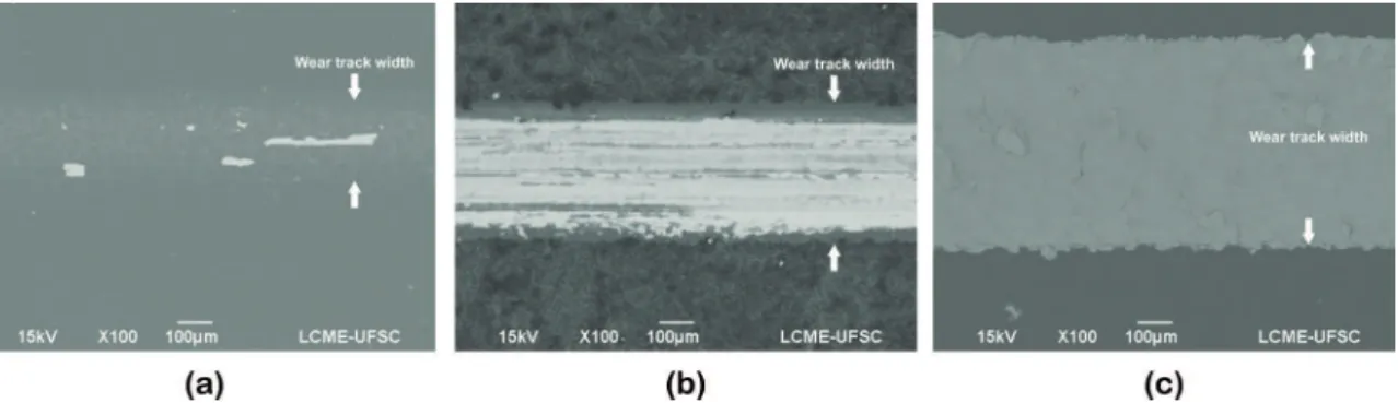
To understand these results, the wear tracks were analysed; the corresponding SEM images are shown in Figure 12.As
demonstrated by the development of the coeicient of friction, the wear tracks were very diferent. At the end of the tests, when the coeicient of friction rapidly increased, a tribolayer
persisted on the ε layer, with small regions containing the
apparent substrate. On the γ’ layer, a tribolayer had developed before being removed, revealing the substrate. The visible bands of this layer could be observed at the end of the test. For the difusion layer, which achieved the longest sliding distance, the ilm was completely removed, and the interface between the wear track and the coating edge was deined. Small portions
under the DLC were also removed due to the higher stresses. In addition, the track width was larger due to the larger normal load. An analysis of these images and results revealed that
the heterogeneous formation of DLC on top of the γ’
nitrided layer was quickly removed during the sliding test
even though little delamination was produced next to the Rockwell-C indentation. This phenomenon occurred because
the indentation was restricted to one point, whereas the sliding tests involved lateral movement. As the counter body slides
along the track, the deformation moves, causing the ilm to
fail. A tribolayer is formed but is quickly removed, ending the low friction regime prematurely. In addition, the same delamination mechanism observed at the indentation border was observed along the side marks of the track, as shown
in Figures 9 and 12.
The coated ε layer, which also exhibited a high roughness with the formation of homogeneous DLC, demonstrated a higher durability; at the end of the test, the tribolayer remained in place even though some pieces
were removed. Therefore, even when the delamination areas were equivalent, the responses of the ε and γ’
conditions were distinct.
Nevertheless, the behaviour of the coated difusion layer was special; under these conditions, the greatest extent of
delamination occurred when the surface presented the highest
durability. To understand this behaviour, the test parameters
must be considered. Whereas the indentation test used a
1474 N load, the load used during the sliding test did not exceed 70 N, meaning that the results were obtained under diferent stress and deformation regimes.
Clearly, a direct correlation between the adhesion tests using Rockwell-C indentation and the durability tests using the sliding movement of the tribometer cannot be attained
because the failure mechanisms may be diferent, resulting
in the distinct crack patterns that could be observed on the ε and γ’ surfaces or in the antagonistic efect on the
difusion surface.
Figure 10: Coating durability of: coated ε-phase surface; coated γ’-phase surface; and coated difusion surface, assessed with incremental
loading reciprocating sliding test performed in tribometer.
Figure 11: Coating durability and adhesion measured by tribometer durability test and Rockwell-C indentation caused by delamination
area of: coated ε-phase surface; coated γ’-phase surface; and coated difusion surface.
Figure 12: Top-down SEM micrographs showing wear tracks of: (a) coated ε-phase surface; (b) coated γ’-phase surface; (c) and coated difusion surface, produced in tribometer durability test.
of the test. To analyse this efect, two additional wear tracks were produced on the coated difusion layer: one interrupted the test at point A in Figure 10 when the friction
was still high, and the other occurred at point B when the friction stabilised to a lower level. Consequently, all
three conditions, speciically the intact coated surface,
the high-friction regime and the low-friction regime,
could be assessed together. The Sq value reveals that the
roughness decreased signiicantly at the beginning of the test (Figure 13).
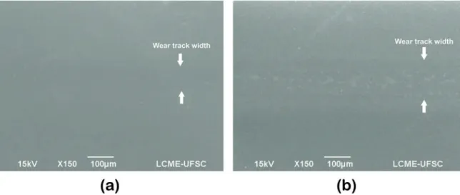
SEM images were collected for the two friction regimes, and they are presented in Figure 14, with the wear tracks marked by arrows. During the irst stopping point of the
test, the friction was high; the roughness was only reduced through surface smoothing, which was almost imperceptible. However, when the test was stopped during the low-friction regime, a tribolayer was observed; although, the roughness level of the tribolayer did not vary, the formation of the layer
was the primary reason that the coeicients of friction were reduced. Therefore, from a tribological perspective, the DLC
coating produced over these nitrided surfaces required an initial smoothing period before the best operation conditions were reached.
The results show that the topography and the type of nitrided layer used directly afected the performance of the DLC-coating. Topographic and morphologic control proved to be extremely important because the conditions
to generate mechanical support also improve roughness
and negatively afect the tribological performance of the
multifunctional system.
4. Conclusions
Roughness was observed to afect the tribological performance of DLC ilms deposited over nitrided layers.
Depending on the processing conditions and resulting nitrided
layers, the durability could be enhanced and the coeicient
of friction could be reduced.
The best conditions for this system involved depositing the DLC over the nitrided difusion layer that, after an initial
smoothing period, demonstrated the best tribological performance. A direct comparison between the results of the adhesion tests performed using Rockwell-C indentation and those obtained from durability tests performed in a tribometer is
not possible unless stress and deformation ields, as well as
other characteristics of the surfaces, are assessed.
Figure 13: Sq roughness parameter of difusion layer wear track
measured on: the initial intact surface; high-friction regime; and low-friction regime.
Figure 14: Top-down SEM micrographs of coated difusion surface showing wear tracks on: (a) High friction regime; and (b) Low friction
regime, indicated by tribometer durability test.
The processing conditions used to grow the ε and γ’
compound layers increased the roughness of the surface
by a factor of approximately two relative to that achieved under the conditions used to grow only the difusion layer.
5. Acknowledgements
The authors acknowledge the following Brazilian agencies for funding this research: CNPq, BNDES, CAPES-PROEX and Whirlpool/Embraco.
6. References
1. Donnet C, Erdemir A, eds. Tribology of Diamond-Like Carbon Films - Fundamentals and Applications. New York: Springer;
2008. 664 p. doi:10.1007/978-0-387-49891-1.
2. Erdemir A, Eryilmaz OL, Nilufer IB, Fenske GR. Efect of source
gas chemistry on tribological performance of diamond-like carbon
ilms. Diamond and Related Materials. 2000;9(3-6):632-637.
doi:10.1016/S0925-9635(99)00361-1.
3. Erdemir A, Eryilmaz OL, Fenske G. Synthesis of diamondlike carbon ilms with superlow friction and wear properties. Journal of Vacuum Science & Technology A. 2000;18(4):1987-1992. doi:10.1116/1.582459.
4. Grill A. Tribology of diamondlike carbon and related materials:
an updated review. Surface and Coatings Technology.
1997;94-95:507-513. doi:10.1016/S0257-8972(97)00458-1.
5. Buršíková V, Navrátil V, Zajíčková L, Janča J. Temperature dependence of mechanical properties of DLC/Si protective coatings prepared by PECVD. Materials Science and Engineering: A.
2002;324(1-2):251-254. doi:10.1016/S0921-5093(01)01320-X.
6. Dorner A, Schürer C, Reisel G, Irmer G, Seidel O, Müller E. Diamond-like carbon-coated Ti6Al4V: inluence of the coating
thickness on the structure and the abrasive wear resistance. Wear.
2001;249(5-6):489-497. doi:10.1016/S0043-1648(01)00587-7.
7. Horiuchi T, Yoshida K, Okuda T, Kano M, Kumagai M, Suzuki T. Session 01: DLC coatings OA 01 P2009-245 evaluation of adhesion strength and wear resistance of DLC ilms. Surface and Coatings Technology. 2010;205(Suppl 1):S188-S195.
doi:10.1016/j.surfcoat.2010.07.068.
8. Dalibon EL, Charadia R, Cabo A, Trava-Airoldi V, Brühl SP. Evaluation of the mechanical behaviour of a DLC ilm on plasma nitrided AISI 420 with diferent surface inishing. Surface and Coatings Technology. 2013;235:735-740. doi:10.1016/j.surfcoat.2013.08.059.
9. Rechberger J, Brunner P, Dubach R. High performance cutting tools with a solid lubricant physically vapour- deposited coating.
Surface and Coatings Technology. 1993;62(1-3):393-398.
10. Pye D. Practical nitriding and ferritic nitrocarburizing. Materials
Park: ASM International; 2003.
11. De Mello JDB, Binder C, Binder R, Klein AN. Efect of nature of
nitride phases on microabrasion of plasma nitrided sintered iron.
Tribology - Materials, Surfaces & Interfaces.
2010;4(4):191-196. doi:10.1179/1751584X10Y.0000000001.
12. Campagna V, Bowers R, Northwood DO, Sun XC, Bauerle
P. Comparison of carbonitriding and nitrocarburising on size
and shape distortion of plain carbon SAE 1010 steel. Surface Engineering. 2010;27(2):86-91. doi:10.1179/02670841
13. Christiansen T, Somers MAJ. Controlled dissolution of colossal
quantities of nitrogen in stainless steel. Metallurgical and Materials Transactions A. 2006;37(3):675-682. doi:10.1007/ s11661-006-0039-5.
14. Funatani K. Low-temperature salt bath nitriding of steels.
Metal Science and Heat Treatment. 2004;46(7):277-281.
doi:10.1023/B:MSAT.0000048834.48163.2e.
15. Wu D, Kahn H, Dalton JC, Michal GM, Ernst F, Heuer AH.
Orientation dependence of nitrogen supersaturation in austenitic stainless steel during low-temperature gas-phase nitriding. Acta Materialia. 2014;79:339-350. doi:10.1016/j.actamat.2014.07.007.
16. Pinedo CE, Monteiro WA. Surface hardening by plasma nitriding
on high chromium alloy steel. Journal of Materials Science Letters. 2001;20(2):147-150.
17. Meletis EI, Erdemir A, Fenske GR. Tribological characteristics of DLC ilms and duplex plasma nitriding/DLC coating
treatments. Surface and Coatings Technology.
1995;73(1-2):39-45. doi:10.1016/0257-8972(94)02375-1.
18. Michler T, Grischke M, Traus I, Bewilogua K, Dimigen H. DLC Films deposited by bipolar pulsed DC PACVD. Diamond and Related Materials. 1998;7(2-5):459-462. doi:10.1016/S0925-9635(97)00236-7.
19. Dalibon EL, Trava-Airoldi V, Pereira LA, Cabo A, Brühl SP.
Wear resistance of nitrided and DLC coated PH stainless steel.
Surface and Coatings Technology. 2013;255:22-27. doi:10.1016/j.
surfcoat.2013.11.004.
20. ASM International. ASM Handbook Vol 4: Heat-treating.
Materials Park: ASM International; 1991.
21. Klein AN, Cardoso RP, Pavanati HC, Binder C, Maliska AM, Hammes G, et al. DC Plasma Technology Applied to Powder
Metallurgy: an Overview. Plasma Science and Technology. 2013;15(1):70-81. doi:10.1088/1009-0630/15/1/12.
22. Jeong BY, Kim MH. Efects of pulse frequency and temperature
on the nitride layer and surface characteristics of plasma nitrided stainless steel. Surface and Coatings Technology.
2001;137(2-3):249-254. doi:10.1016/S0257-8972(00)01095-1.
23. Karakan M, Alsaran A, ̧elik A. Efects of various gas mixtures on plasma nitriding behavior of AISI 5140 steel. Materials
Characterization. 2002;49(3):241-246.
24. Masuko M, Kudo T, Suzuki A. Efect of surface roughening of
substrate steel on the improvement of delamination strength and tribological behavior of hydrogenated amorphous carbon coating under lubricated conditions. Tribology Letters.
2013;51(2):181-190. doi:10.1007/s11249-013-0106-1.
25. Singh GP, Alphonsa J, Barhai PK, Rayjada PA, Raole PM, Mukherjee S. Efect of surface roughness on the properties of the layer formed on AISI 304 stainless steel after plasma nitriding.
Surface and Coatings Technology. 2006;200(20-21):5807-5811.
doi:10.1016/j.surfcoat.2005.08.149.
26. Vidakis N, Antoniadis A, Bilalis N. The VDI 3198 indentation
test evaluation of a reliable qualitative control for layered compounds. Journal of Materials Processing Technology.
2003;143-144:481-485. doi:10.1016/S0924-0136(03)00300-5.
27. Heinke W, Leyland A, Matthews A, Berg G, Friedrich C, Broszeit E. Evaluation of PVD nitride coatings, using impact, scratch
and Rockwell-C adhesion tests. Thin Solid Films.
1995;270(1-2):431-438. doi:10.1016/0040-6090(95)06934-8.
28. Ikeyama M, Nakao S, Miyagawa Y, Miyagawa S. Efects of Si content in DLC ilms on their friction and wear properties. Surface and Coatings Technology. 2005;191(1):38-42. doi:10.1016/j.
surfcoat.2004.08.075.
29. Nakanishi K, Mori H, Tachikawa H, Itou K, Fujioka M, Funaki Y. Investigation of DLC-Si coatings in large-scale production using DC-PACVD equipment. Surface & Coatings Technology.
2006;200(14-15):4277-4281. doi:10.1016/j.surfcoat.2005.02.167.
30. De Mello JDB, Binder R. A methodology to determine surface durability in multifunctional coatings applied to soft substrates.
Tribology International. 2006;39(8):769-773. doi:10.1016/j. triboint.2005.07.015.
31. Mason RS, Pichilingi M. Sputtering in a glow discharge ion source-pressure dependence: theory and experiment. Journal of Physics D: Applied Physics. 1999;27(11):2363-2371. doi:10.1088/0022-3727/27/11/017.
32. Pérez R EA, Souza RM. Numerical and experimental
analyses on the contact stresses developed during single and successive indentations of coated systems. Surface and Coatings Technology. 2004;188-189:572-580. doi:10.1016/j.
surfcoat.2004.07.014.
33. Pachler T, Souza RM, Tschiptschin AP. Finite element analysis
of peak stresses developed during indentation of ceramic coated steels. Surface and Coatings Technology.
2007;202(4-7):1098-1102. doi:10.1016/j.surfcoat.2007.07.041.
34. Straford KN, Subramanian C, Wilks TP. Properties and characteristics
of advanced tribological surface coatings and the assessment of
quality-for-performance for enhanced manufacturing eiciency.
Journal of Materials Processing Technology.