*e-mail: [email protected]
Wear Mechanisms of Dental Composite Restorative Materials
by Two Different in-vitro Methods
Juliana Antonino de Souza, Liliane Canuto Dolavale, Sergio Alvaro de Souza Camargo*
Metallurgical and Materials Engineering Department,
Alberto Luiz Coimbra Institute for Graduate Studies and Research in Engineering – COPPE, Federal University of Rio de Janeiro – UFRJ, CP 68505, CEP 21941-972, Rio de Janeiro, RJ, Brazil
Received: April 11, 2012; Revised: October 6, 2012
In this work two very simple apparatuses, namely the ball crater (or ball-on-plate) and the linear reciprocating (or pin-on-plate) tests, were used in order to investigate the wear mechanisms of TPH Spectrum and Resilab Master dental composite resins. Loads in the range of 100 g to 1 kg and a total number of up to 24000 cycles were employed. During some of these tests, aqueous aluminum oxide suspensions were used as abrasive agent either diluted or not in distilled water. In case of the ball-on-plate test wear is dominated by abrasive and/or adhesive mechanisms, and is characterized by scratches which are composed of wear defects comprising particle detachment, wear of the polymer matrix and ceramic particle abrasion. However, the relative contributions of the two wear mechanisms could not be determined separately. In case of the pin-on-plate test wear is governed by the fatigue mechanism, although abrasive and adhesive wear mechanism are also present. After a certain number of cycles fatigue wear dominates the wear behavior and results in severe material loss. This mechanism seems to be more important in case of more brittle materials and when higher loads are employed. Qualitative analysis of the results suggests that the combination of these two very simple methods under appropriate conditions can yield sound results which may be representative of a number of clinical situations.
Keywords: wear, dental composites, abrasive wear
1. Introduction
Wear in the oral cavity is a complex phenomenon which depends on numerous factors. From a strictly tribological point of view, the term wear applies to the loss of material that result from the mechanical contact and relative movement of two bodies in the presence or not of a third body or medium. In addition to that, other effects caused solely from the chemical attack of aggressive liquids or fluids eventually present in the mouth may also result in wear, although they do not include friction between materials. There are several (tribological) wear mechanisms described in the literature: abrasive, adhesive, fatigue, impact, corrosive and so on1,2. Abrasive wear occurs when a hard surface slides over a softer surface and damage it by plastic deformation or fracture. The same type of mechanism occurs when the hard surface is replaced for a soft surface containing or in the presence of hard particles. In the last case one has a three-body type of wear, whereas the two previous ones are simply two-body3. Adhesive wear occurs between two materials when the surfaces adhere and the shear action results in detachment of fragments of one material and attachment to the other one. Fatigue wear results from the repeated sliding or rolling of one surface over the other. Impact wear takes place when two surfaces collide with each other while having large
relative velocities in the direction normal to their interface. When the impacting body is in the form of solid particles, or others, wear is named erosive. When the tribological action takes place in a corrosive environment, corrosive wear arises and may increase wear rates dramatically. In principle, all of these wear mechanisms can take place in the oral cavity, either isolated or in association to each other. This is basically the reason why it is so complex to simulate wear of dental materials.
In spite of great development of dental materials in the last decades, wear of restorative materials is still a major concern especially when one deals with composite resins. Several aspects of the composition and structure of composite resins directly affect and limit their wear resistance. Size, shape and amount of fillers, as well as their mechanical properties, interface adhesion between matrix and filler particles, the characteristics of the polymer matrix itself and its curing process, are some of the main factors that affect the wear properties of dental composites4.
several others. Although many of these equipment are commercially available, wear simulators may be expensive and are not readily available at most laboratories involved in the evaluation of properties and materials development. Therefore, a widely used alternative is to employ for this purpose much simpler standard wear tests, such as: pin-on-disk14, ball-crater15, reciprocating16, abrasive disk17, taber abraser18 and many others19,20.
It is nowadays well accepted that no test can provide an undisputable evaluation when one has in mind the wear performance of dental materials, as different methods involve different wear mechanisms resulting in different wear rates. Indeed, when performing a carefully controlled round-robin wear test using five different wear simulators, other authors obtained a great variation of results among the different test centers or test methods21. As a consequence, when the general wear resistance of a material has to be evaluated it is advised to use at least two different wear methods making, from a practical point of view, this evaluation even more difficult. In addition to that, as the different wear testing methods emphasize different wear mechanisms it would be desirable to have a clear picture of the correlation between wear tests conditions and clinical prescription of restorative materials so as to obtain more significant figures.
Many models developed for the different wear mechanisms of metallic or ceramic materials can be found in literature, but not for the more complex case of composite resins. Some attempts were made in order to draw a correlation of wear rates and composite materials properties under some specific condition of certain wear mechanisms. For instance, when studying dimetacrylate-based composites submitted to abrasive wear Heintze et al.4 obtained a good correlation between wear index and some of the physical characteristics of the materials. However, a more general comprehension of this problem is still lacking.
In the present work, two very simple apparatuses are used in order to investigate the wear mechanisms of dental composite resins. These are the ball crater (or ball-on-plate) and the linear reciprocating (or pin-on-plate) wear tests. The two tests were employed on two different composites and the wear mechanisms under certain specific conditions are observed and discussed. The results show that under certain conditions the ball-on-plate (BoP) wear test can be very useful for the study of wear governed by abrasive and/or adhesive mechanisms, while the pin-on-plate (PoP) wear test can be successfully employed in the study of wear governed by the fatigue mechanism. Qualitative analysis of the results suggests that the combination of these two very simple tests under carefully chosen conditions can yield sound results which may be representative of a large number of clinical situations.
2. Experimental
2.1.
Samples preparation
2.1.1. Composite resins
For the present study two different resin-based composites were investigated, namely TPH Spectrum and Resilab Master. TPH Spectrum is a light activated material of direct use for anterior and posterior restorations, while Resilab Master is a light activated restorative material for indirect use. Table 1 shows the chemical compositions and manufacturers of both materials. Rectangular shape specimens of each composite with 30 mm length, 8 mm wide and 2 mm thick were obtained using a silicon mold (Stern Tek, Sterngold, USA). The mold was placed on a transparent polyester film resting on a glass plate and manually filled with one single layer of composite resin and covered with a film in the similar way as the bottom. TPH Spectrum composites were photocured using a Ultrablue
Is LED according to the manufacturer specifications. As the length of the specimen exceeds the window diameter of the handheld light probe tip the irradiation was done in four windows with a 8 mm diameter light guide, each of them with a curing time of 20 seconds. Resilab Master was photocured according to the manufacturer specifications during 3 minutes in a photo-polymerization unit equipped with a strobe light source. After 24 hours of polymerization, excess material around the samples was removed by gentle abrasion with 600 and 1200 sandpaper (3 M ESPE, USA). The samples surface were also submitted to paper sanding (600, 800 and 1200 grit) and metallographic polishing with 2 µm and 1 µm aqueous aluminum oxide suspensions (White/Blue alumina, QM Brazil, 120 g/L). With this
process the oxidized surface layer that may be present on the sample surface is completely removed. The samples were then ultrasonically cleaned during 10 minutes in deionized water.
Surface morphologies of the samples before and after the wear tests were observed by scanning electron microscopy (SEM) with a JEOL 6460LV microscope working at 20 kV.
2.1.2. Ceramic pins
Ceramic pins were made from a wax sprue, measuring 2 mm diameter and 7 mm in length. The lost wax casting technique was used to obtain the dental ceramic pins. The wax sprue was imbedded in plaster or clay and burned out leaving a space where the wax was originally placed, then filled with pre-sintered ceramic through a hole with the aid of pneumatic pressure and then densely sintered at 830 °C in a high temperature and high pressure furnace (Inceramat, Dentsply). After preparation, the pins were finished and
Table 1. Composition and manufacturers of the composite resin materials.
Material Composition Manufacturer
TPH Spectrum Matrix: BisGMA, BisEMA and TEGDMA.
Filler: barium alumino boro silicate and colloidal silica. Dentsply – USA
Resilab Master Matrix: BisGMA, BisGEMA, UDMA and TEGMA.
polished with sandpapers of different grit sizes (400, 600 and 1200) in order to make their surfaces flat. In a second step the pins were polished as described in previous section with aqueous aluminum oxide suspensions, resulting in smooth and shiny surfaces.
2.2.
Wear tests
2.2.1. Ball-on-plate (BoP)
Ball-on-plate wear tests were carried out in a ball-cratering machine (Gentest, Gencoa, UK). A detailed description of the BoP wear test has been given by Gee et al.22. In this work the samples rested over a 15 mm radius chromium steel ball continuously rotating at 50 rpm (which corresponds to a linear velocity of 0.078 m/s at the point of contact) while a dead-weight load in the range of 0.1 to 1 kg was applied as normal load to the sample. The tests were carried with a total number of up to 24000 cycles. During some of these tests, an aqueous aluminum oxide suspension (White/Blue alumina,
QM Brazil) dropped continuously by a peristaltic pump feed with a flow of 1 mL/min was used as abrasive agent. The alumina suspensions were used either at the original 120 g/L concentration or diluted in distilled water. The slurry was dropped over the sphere onto a spot just before the sphere/sample contact region. Each test was repeated six times on randomly chosen samples. The obtained result for a certain material under a certain condition is the average value (and corresponding standard deviation) of the six tests. The locations of the impressions on each the samples were also randomly chosen.
After the tests, the samples were gently rinsed with deionized water and dried in ambient air. An Olympus BX60M (Japan) optical microscope was used to measure the diameter of the circular wear craters in two orthogonal directions, i.e. the sliding direction and the direction perpendicular to it. The average value of crater diameter, d,
was then used to obtain the volume, V, of removed material as follows: π = + 2 2 . 3 6 4 h d
V h (1)
where h is the depth of the wear crater and is given by:
= − − 1/2 2 2 4 d
h R R (2)
where R is the sphere radius (15 mm). Therefore, after N turns the wear rate, W, can be obtained using the equation:
=
. V W
P L (3)
where P is the load used in the tests and L = 2π.R.N is the sliding distance. The test conditions employed in this work were based on those of Antunes and Ramalho15.
2.2.2. Pin-on-plate (PoP)
The equipment used in this test was developed in our laboratory. In this equipment the sample rests on a
micrometric positioned table that can be controlled by a step motor. Over the sample a counter-body in the form of a pin is positioned, upon which a dead-weight load can be placed. The pin is attached to a lever-arm and on its opposite side there is a counter-weight. A computer controls the step motor and therefore the movement of the sample at a desired scan length and speed. Similarly to the BoP tests, the PoP tests also can be performed under dry, wet or abrasive conditions. In this equipment a load in the range of 0.1 to 1 kg can be applied to the pin while the scan amplitude and speed can be varied up to 10 mm and 10 mm/s, respectively. In this work, the PoP tests were carried out with amplitude of 0.5 mm, speed of 0.5 mm/s and a total number of wear cycles of up to 24000 (one wear cycle is counted every time the sample passes through the middle position). For each wear test, the pin was replaced by a new one. After the tests, the samples were gently rinsed with deionized water and dried in ambient air. The profiles of the wear scars were measured by stylus profilometry (Dektak IIA, Sloan Technology, USA) in the two directions parallel and perpendicular to the sliding direction. A total of six measurements were performed for each wear scar. From the obtained profiles the wear volume was estimated. The wear rate can be then calculated by Equation 3, where in this case L is the total sliding distance of the test. Number of samples and repetitions were the same as in the previous case. The test conditions employed in this work were based on those of Ramalho and Antunes16.
3. Results and Discussion
The main goal of the present work is to investigate the main wear mechanisms occurring during the wear tests performed with ball-on-plate and pin-on-plate apparatuses. Therefore, from the various experimental conditions employed only some results which are thought to be significant for this purpose will be presented here.
In case of ball-on-plate wear tests, wear of the material is observed in the form of scratches parallel to the ball sliding direction that result from the abrasive action of the metal sphere and/or alumina particles of the abrasive suspension. The scratches present on the samples surface are isolated from each other and their number clearly increases as the number of wear cycles of the test is increased. Basically the same wear process continues without changes up to 24000 wear cycles.
Apart from a difference on their number, similar scratches are formed irrespective to the lubricating conditions of the test, either dry, wet or with alumina abrasive slurry. Figure 1 shows a SEM micrograph of the wear scratches in the case of Resilab Master sample
after performing 1500 cycles under dry conditions, while Figure 2 shows a TPH Spectrum sample after performing 8000 cycles with the use of alumina abrasive slurry. In these figures, the wear scars appear as brighter regions parallel to the sliding direction that result from the removal of the polymeric matrix and ceramic particles. In spite of the obvious differences of the microstructure of the two different composite resins the morphology of the wear scars appear to be quite similar in the two cases.
in a linear fashion, comprising different mass loss processes. Figure 3 shows these mechanisms in the case of TPH Spectrum samples. Particle detachment, wear of the polymer matrix and ceramic particle abrasion are some wear mechanisms that can be clearly identified in these figures. Figure 4 shows ceramic particle pull-out and polymer matrix removal in the case of Resilab Master sample.
In principle, two different wear mechanisms may be responsible for such effects, namely, abrasive and adhesive wear mechanisms. Abrasion may result from the action of the metal ball surface imperfections which have a high hardness and, therefore, can plough out the polymer matrix and/or ceramic particles from the sample surface, resulting on the scratches shown. Likewise, when using alumina abrasive suspension similar mechanisms can occur in an even more effective way due to the action of the hard alumina particles. Obviously, in this last case wear rates are larger than under dry conditions and a decreasing wear rate was observed when the alumina suspension is diluted in de-ionized water.
An important point to be mentioned is that particle removal occurs even when alumina suspension is not used at all (dry tests). As clearly shown in Figure 4 (for the case of Resilab Master) particles may be removed together
with a substantial amount of polymer matrix. No qualitative differences could be observed for BoP tests under different conditions (dry, wet or abrasive slurry) so that the wear mechanisms involved seem to be essentially the same under the conditions employed.
Based on these results one can undoubtedly conclude that abrasive wear takes place during BoP wear tests, under all the conditions used. However, one cannot discard the contribution of adhesive wear for such processes, as it is in fact very difficult to separate the two mechanisms on the present results. Although the specific conditions of the tests in principle define the contributions of the abrasive and adhesive wear to the total wear rate, at the present stage it is not possible to obtain those individual contributions separately. For instance, the use of an alumina abrasive
Figure 3. SEM micrograph of the inside of the wear crater of a TPH Spectrum sample after performing 8000 cycles with the ball-on-plate wear test with blue alumina abrasive slurry diluted 1:10 in distilled water.
Figure 2. SEM micrograph of the inside of the wear crater of a TPH Spectrum sample after performing 8000 cycles with the ball-on-plate wear test with blue alumina abrasive slurry diluted 1:10 in distilled water. The arrow indicates the approximate sliding direction.
Figure 1. SEM micrograph of the inside of the wear crater of a Resilab Master sample after performing 1500 cycles with the ball-on-plate wear test under dry conditions. The arrow indicates the approximate sliding direction.
increase, the microcracks propagate forming a network of interconnected cracks (Figure 8). As this process continues, severe material loss is observed as shown in Figures 9 to 11. As it is apparent from these figures subsurface cracks seem to be formed as well, which result in spalling of relatively large portions of material, as shown in Figure 9 and 10. Figure 11 shows the Resilab Master sample surface after
severe material loss. The described behavior is less clear in case of TPH Spectrum.
The observed behavior is typical of a fatigue wear mechanism and is related to the cyclic nature of this test23. The fatigue wear mechanism, which is particularly strong in case of brittle materials, occurs under rolling and sliding conditions and is revealed when the formation of surface and subsurface microcracks initiates after a certain number of cycles is achieved. Before that, such mechanism is quite difficult to be detected or identified. The formation of surface microcracks can be understood based on the fact that as the pin slides over the sample, the point of maximum shear stress is located at some point near or below the surface. This leads to the formation of microcracks and severe wear. This is particularly important in case of brittle materials. slurry allows the control of the abrasive wear by ceramic
particles but also affects the contributions of the (two-body) abrasive and adhesive wear mechanisms by the metal ball. Further work is still needed in order to clarify this matter.
It is noteworthy to mention that EDS analysis (not shown here) has shown signs of iron on the surface of abraded ceramic particles of both materials indicating that not only the composite resin is worn out but also the filler particles wear some material out of the steel ball. The use of a ceramic ball, like alumina, could in principle reduce this effect but would probably not affect the overall results presented here.
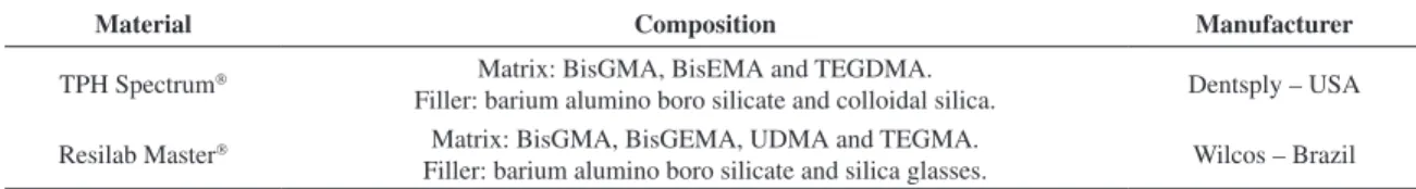
Quantitative determination of wear has shown that the wear volume of the material steadily increases with the number of cycles of the BoP test. This increase is initially at a relatively small rate and after that the wear volume tends to increase linearly with time, corresponding to a constant wear rate. Figure 5 shows this behavior for TPH Spectrum and
Resilab Master samples tested with blue alumina abrasive slurry diluted 1:10 in distilled water and a load of 500 g. Very similar behaviors are observed for both materials. Under the conditions used the steady state wear rates were determined to be approximately 2.5 × 10⁻⁵ mm3.(N.m)–1 and 3.4 × 10⁻⁵ mm3.(N.m)–1 for TPH Spectrum and Resilab
Master samples, respectively.
The pin-on-plate (PoP) wear test reveals a different wear behavior for the same two dental composite materials. At the initial stages of the wear process, a typical behavior of the abrasive and/or adhesive wear mechanisms can be observed, similarly to the case of the previous test. In parallel to that, as the number of cycles increases, a new wear mechanism initiates as shown in Figure 6 for the case of a TPH Spectrum samples. Comparison of Figures 3 and
6 reveals that in addition to wear of the polymer matrix and removal of ceramic particles, in case of the PoP test the formation of surface microcracks also appears.
This effect seems to be much more pronounced in case of Resilab Master samples, as abrasion of the composite resin material and extensive formation of surface microcracks can be seen, as shown in Figure 7. As the number of cycles
Figure 6. SEM micrograph of the inside of the wear crater of a TPH Spectrum sample after 1500 cycles of the pin-on-plate wear test.
Figure 7. SEM micrograph of the inside of the wear crater of a Resilab Master sample after 5000 cycles of the pin-on-plate wear test.
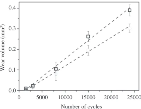
good agreement with the above described behavior as one initially observes relatively low wear rates and after a certain critical point wear increases substantially. Up to about 10000 cycles the wear rate is approximately constant at about 9 × 10⁻⁵ mm3.(N.m)–1 for both materials. This behavior corresponds to the dashed line labeled (1) in Figure 12 and is roughly of the same order as the wear rates observed by the BoP test. After that point, the wear rate increases substantially due to the onset of fatigue wear. In case of Resilab Master an increase of the wear rate of about a
factor of 15 is observed to approximately 1.3 × 10⁻³ mm3. (N.m)–1, which corresponds to the dashed line labeled (2) in Figure 12. In case of TPH Spectrum some increase of
wear rate is observed, but a second wear regime at a constant wear rate could not be clearly seen.
When performing a round-robin wear test with five different wear simulators on ten different dental restorative materials, Heintze et al.21 analyzed seven different wear parameters and concluded that three different wear mechanisms can be distinguished: type 1 is a mixed type Figure 8. SEM micrograph of the inside of the wear crater of a
Resilab Master sample after 10000 cycles of the pin-on-plate wear test.
Figure 9. SEM micrograph of the inside of the wear crater of a Resilab Master sample after performing after 13000 cycles of the pin-on-plate wear test.
Figure 10. SEM micrograph of the inside of the wear crater of a Resilab Master sample after performing after 13000 cycles of the pin-on-plate wear test.
Quantitative results of wear are presented in Figure 12 for TPH Spectrum and Resilab Master samples tested in distilled water and a load of 1 kg. The results are in
Figure 11. SEM micrograph of the inside of the wear crater of a Resilab Master sample after performing the after 24000 cycles of pin-on-plate wear test.
the wear mechanisms of two dental composite resins: TPH Spectrum and Resilab Master. From the observed results
the following conclusions can be drawn:
• Underappropriateconditionstheball-on-plate(BoP)
wear test can be very useful for the study of wear governed by abrasive and/or adhesive mechanisms. This is valid for a certain range of experimental conditions, such as, loads between 0,1 and 1 kg, number of cycles up to 24000 and under dry and wet conditions or using alumina abrasive slurry. Although the wear rate can be controlled by the employed conditions of the test and change the relative contributions of the two wear mechanisms, these contribution could not be obtained separately. Further work is still necessary in order to perform a deeper investigation of this point;
• Thepin-on-plate(PoP)weartestcanbesuccessfully
employed for the study of wear governed by the fatigue mechanism. Although in this test abrasive and adhesive wear mechanism are also present, after a certain number of cycles fatigue wear strongly increases dominating the wear behavior completely. This mechanism seems to be more important in case of more brittle materials and when higher loads are employed; and
• Qualitativeanalysisoftheresultssuggeststhatthe
combination of these two very simple tests under carefully chosen conditions can yield sound results which may be representative of a number of clinical situations.
of wear composed of adhesive, attrition and fatigue wear mechanisms and results from the direct contact between the material and its antagonist; type 2 is basically a three-body type of abrasive wear and type 3 is mainly due to fatigue. The tests which are dominated by the latter mechanism did not agree well with the results of all the others tests21.
From a tribological point of view, basically the same wear mechanisms are involved in the present tests. More than that, the specific conditions under which the tests are performed allow one to emphasize the different wear mechanisms. For example, in case of BoP tests three-body abrasive wear can be increased by the use of an abrasive slurry while two-body dominates under dry conditions; in case of PoP fatigue wear is increased when the number of cycles and/or load is increased; and so on.
In conclusion, the results here presented suggest that it is possible to conceive a wear test methodology for dental restorative materials based on these two very simple wear tests. This methodology can in principle include tests at different experimental conditions so as to emphasize wear by three different mechanisms, e.g., abrasive, adhesive and fatigue wear mechanisms. The results of these tests when used in combination may be representative of a large number of clinical situations.
4. Conclusions
In this work two very simple apparatuses, namely the ball crater (or ball-on-plate) and the linear reciprocating (or pin-on-plate) wear tests, were used in order to investigate
References
1. Rabinowicz E. Friction and wear of materials. 2nd ed. John Wiley and Sons; 1995.
2. Bhushan B. Introduction to tribology. John Wiley and Sons; 2002.
3. Hahnel S, Schultz S, Trempler C, Ach B, Handel G and Rosentritt M. Two-body wear of dental restorative materials. Journal of the Mechanical Behavior of Biomedical Materials. 2011; 4:237-244. PMid:21316610. http://dx.doi. org/10.1016/j.jmbbm.2010.06.001
4. Heintze SD, Zellweger G and Zappini G. The relationship between physical parametrs and wear of dental composites.
Wear. 2007; 263:1138-1146. http://dx.doi.org/10.1016/j. wear.2006.12.010
5. Lambrechts P, Debels E, Landuyt KV, Peumans M and Meerbeek BV. How to simulate wear? Overview of existing methods. Dental Materials. 2006; 22:693-701. PMid:16712913. http://dx.doi.org/10.1016/j.dental.2006.02.004
6. De Gee AJ and Pallav P. Occlusal wear simulation with the ACTA wear machine. Journal of Dentistry. 1994; 22:S21-S27. http://dx.doi.org/10.1016/0300-5712(94)90167-8
7. Mehl A, Gloger W, Kunzelmann K-H and Hickel R. A new optical 3-D device for the detection of wear. Journal Dental Research. 1997; 76:1799-1807. http://dx.doi.org/10.1177/00 220345970760111201
8. Krejci I, Reich T, Lutz F and Albertoni M. An in-vitro test procedure for evaluating dental restoration systems. 1.
A computer-controlled mastication simulator. Schweiz Monatsschr Zahnmed. 1990; 100:953-960. PMid:2399447. 9. Condon JR and Ferracane JL. Evaluation of composite
wear with a new multi-mode oral wear simulator. Dental Materials. 1996; 12:218-226. PMid:9002838.
10. Leinfelder KF, Beaudreau RW and Mazer RB. An in vitro device for predicting clinical wear. Quintessence International. 1989; 20:755-761. PMid:2639390.
11. Yap AUJ, Ong LFKL, Teoh SH and Hastings GW. Comparative wear ranking of dental restoratives with the BIOMAT wear simulator. Journal Oral Rehabilitation. 1999; 26:228-235. http://dx.doi.org/10.1046/j.1365-2842.1999.00359.x
12. Sakaguchi RL, Douglas WH, DeLong R and Pintado MR. The wear of a posterior composite in an artificial mouth: a clinical correlation. Dental Materials. 1986; 2:235-240. http://dx.doi. org/10.1016/S0109-5641(86)80034-3
13. Heintze SD and Forjanic M. Surface roughness of different dental materials before and after simulated toothbrushing in vitro. Operative Dentistry. 2005; 30:617-626. PMid:16268397.
14. Nagarajan VS, Jahanmir S and Thompson VP. In vitro contact wear of dental composites. Dental Materials. 2004; 20:63-71. http://dx.doi.org/10.1016/S0109-5641(03)00069-1
15. Antunes PV and Ramalho A. Study of abrasive resistance of composites for dental restoration by ball-cratering.
Wear. 2003; 255:990-998. http://dx.doi.org/10.1016/ S0043-1648(03)00150-9
20. Bianchi EC, Ulhôa MPM, Aguiar PR, De Freitas CA and Gonçalves GMB. Analysis of Polymerization Time on Abrasive Wear of Dental Resins. Materials Research. 2010; 13:41-44. http://dx.doi.org/10.1590/S1516-14392010000100010
21. Heintze SD, Zapini G and Rousson V. Wear of ten dental restorative materials in five wear simulators - Results of a round robin test. Dental Materials. 2005; 21:304-317. PMid:15766577. http://dx.doi.org/10.1016/j.dental.2004.05.003
22. Gee MG, Gant A, Hutchings I, Bethke R, Schiffman K, Van Acker K et al. Progress towards standardisation of ball cratering. Wear. 2003; 255:1-13. http://dx.doi.org/10.1016/ S0043-1648(03)00091-7
23. Padipatvuthikul P, Jarad FD and Mair L. Determination of surface and subsurface fatigue damage in dental composites.
Wear. 2010; 268:1483-1489. http://dx.doi.org/10.1016/j. wear.2010.02.025
Wear. 2007; 263:1095-1104. http://dx.doi.org/10.1016/j. wear.2007.01.086
17. L a p p a l a i n e n R , Y l i - U r p o A a n d S e p p a L . We a r o f d e n t a l r e s t o r a t ive a n d p r o s t h e t i c m a t e r i a l s i n vitro. Dental Materials. 1989; 5:35-37. http://dx.doi. org/10.1016/0109-5641(89)90090-0
18. Winkler MM, Greener EH and Lautenschlager EP. Non-linear in vitro wear of posterior composites with time. Dental Materials. 1991; 7:258-262. http://dx.doi.org/10.1016/ S0109-5641(05)80025-9
19. Bianchi EC, Da Silva EJ, Monici RD, De Freitas CA and Bianchi ARR. Development of new standard procedures for the evaluation of dental composite abrasive wear.