UNIVERSIDADE DE LISBOA
FACULDADE DE CIÊNCIAS
DEPARTAMENTO DE ENGENHARIA GEOGRÁFICA, GEOFISICA E ENERGIA
Smart Grid
Mestrado Integrado em Engenharia da Energia e do Ambiente
Tiago Miguel Pereira da Rocha
Dissertação orientada por:
João Manuel de Almeida Serra
2
Índex
Glossary... 4 Agradecimentos ... 8 Abstract ... 9 List of Figures ... 10 List of tables ... 11 Chapter 1 - Introduction ... 121.1 Background and Motivations ... 12
1.2 Objectives ... 13
1.3 Framework ... 14
Chapter 2 - Smart Grid Concept ... 17
2.1 Definition ... 17
Chapter 3 - Infrastructure System ... 19
3.1 Introduction ... 19 3.2 Energy Infrastructures ... 19 3.2.1 Power Generation ... 20 3.2.2 Transmission Grid ... 22 3.2.3 Distribution Grid ... 24 3.2.4 Microgrid ... 26
3.2.5 Renewable Energy Sources ... 27
3.3 Data Management Infrastructures ... 28
3.3.1 Metering and Measurement ... 29
3.3.2 Monitoring and Measurement ... 30
3.4 Communication Infrastructures ... 34
3.4.1 Wireless Technologies ... 35
3.4.2 Wired Technologies ... 39
Chapter 4 - Management System ... 42
4.1 Introduction ... 42
4.2 Objectives ... 42
4.2.1 Energy Efficiency and Demand Profile ... 42
4.2.2 Utility Cost and Price Stabilization ... 44
4.2.3 Emission Control ... 46
Chapter 5 - Protection System ... 48
3
5.2 System Reliability and Failure Protection ... 48
5.2.1 Failure Protection Mechanism... 48
5.2.2 Failure Prediction and Prevention ... 49
5.2.3 Failure Identification, Diagnosis and Recovery ... 50
5.2.4 Security and Privacy ... 51
Chapter 6 - Microgrid ... 55 6.1 Introduction ... 55 6.2 Architectures/components ... 58 6.3 Management System ... 61 6.4 Communication infrastructure ... 63 6.5 Protection ... 64 6.6 Microgrid Design ... 69 6.6.1 HOMER SOFTWARE ... 70
6.6.2 Case Study - Grid-Connected Microgrid ... 73
6.7 Economic ... 75
6.7.1 Case Study – Economic Services ... 81
6.8 Regulatory Environment and Incentive Programs ... 85
Chapter 7 - Conclusions ... 88
4
Glossary
AC Alternating Current- In alternating flow of electricity the electric
charge periodically reverses in direction.
AMI Automatic Metering Infrastructure- Infrastructure that allows the
measurement and analysis of the energy consumption in order to communicate the results to measurement devices when that is required. AMR Automatic Metering Reading- Technology that automatically collects
the energy consumption that is then transferred to a database for billing or troubleshoot analysis.
CT Current Transformer- Device used to measure electric alternating
currents and reduce current and voltage.
CVPP Commercial Virtual Power Plant- Technical part involved in a virtual
power plant.
DC Direct Current- In a direct flow of electricity there is a unidirectional
motion of electric charge.
DER Distributed Energy Resource- Decentralized and modular energy
production systems located near the consumption area with capacity of 10MW or less.
DFT Discrete Fourier Transform- Function that converts the original
domain of another function to the frequency domain.
DG Distributed Generation- Decentralized energy production unit.
DMS Distribution Management System- Set of applications designed to
monitor and control the distribution grid in an efficient and reliable way.
DOE Department of Energy- Department of the United States of America
government designed to implement rules related to the energetic politic and handling nuclear material
DS Distributed Storage- Decentralized storage units.
EMC Energy Management Controller- Device that uses both prices and
user preferences to control power usage at home. It can be standalone or embedded in a smart meter.
EMI Electro Magnetic Interface- Operation disruption of an electronic
device with affects it´s electric circuit due to the electromagnetic induction emitted by an external function.
EU 20-20-20 Set of legislation rules imposed by European Union with the objective of reach certain goals environmental and energy wise. The goals are the
5 reduction of 20% in greenhouse gases emissions, 20% of renewable energy in the EU generation mix and 20% improvement in energy efficiency. All of these objectives must be accomplished until 2020. FACTS Flexible AC Transmission Systems- Set of equipment using power
electronics for transmission control in alternating current.
FERC Federal Energy Regulatory Commission- Independent agency design
to regulate the energy transmission in the USA. Furthermore, it reviews proposes to build liquefied natural gas terminals and interstate natural gas pipelines.
GHG Greenhouse Gases- Gases that absorb and emit radiation for the
atmosphere in the thermic infrared zone causing greenhouse effect. GIS Geographical Information System- Computed system capable of
doing the geographical data treatment.
GPS Global Position System- Space-based satellite navigation system
providing location and information about the weather in every climacteric conditions in every part of the globe.
HVDC High Voltage DC- Technology used to increase power transmission
efficiency in long distances using direct current coming from points producing this kind of current.
IED Intelligent Electronic Devices- Microprocessor-based controllers of
power system equipment such as circuit breakers, transformers and capacitor banks.
IRENA International Renewable Energy Agency- Intergovernmental
organization that supports and encourages governments to implement politics and investments in renewable energy.
LAN Local Area Network- Set of computers and other devices which share
the same communication line or the same wireless link. LV Low Voltage- As for MV, there are several values that can be
considered but in this case it is assumed that LV are all the voltage values until 1000V.
MAS Multiagent System- Computed system composed by multiple
intelligent agents in an environment.
MCB Miniature Circuit Breaker- Electric switches automatically operated
design to protect an electric circuit from damage caused by overload or short circuits.
MG Microgrid- Small scale power grid which can operate independently or
in conjunction with the area´s main grid.
6 MV Medium Voltage- For energy transmission purposes the medium
voltage is associated with values ranging from 1000V to 36000V. Note that these numbers are different for various areas in the world.
NREL National Renewable Energy Laboratory- It develops technologies
and procedures in the renewable energy and energy efficiency areas and transfer that knowledge to surpass some issues related to these areas in the USA.
PCC Point of Common Coupling- Point in the public electric grid where it
is possible to connect a microgrid or another type of consumer.
PDC Phasor Data Concentrators- Equipment that receives and synchronize
data coming from PMUs in order to produce an aligned data current in real time.
PLC Power Line Communication- Technology used to transfer data
through the electric grid.
PMU Phasor Measurement Unit- Device used to measure electric waves in
an electric grid.
PT Potential Transformer- Devices that allows lower the systems’
voltage to a safe value in order to be transported to rating meters and relays.
RCD Residential Current Device- Electrical wiring device that connects to a
circuit if it detects that the electric current is not balanced between the electrified conductor and the neutral one.
REV Reforming the Energy Vision- Initiative created by the New York
state to reformulate the energetic industry through new politics and regulation to improve energy efficiency, better allocation of renewable energy and development of distributed energy resources.
RES Renewable Energy Sources- Renewable energy sources are natural,
with regeneration capability and inexhaustible.
RFID Radio Frequency Identification- Use of electromagnetic wireless
fields to transfer data to identify and track tags automatically attached to objects.
RMS Root Mean Square- Statistical measurement of the magnitude of a
variable quantity such as sinusoids.
RTU Remote Terminal Unit- Microprocessor used to interconnect the
physical world to a distributed control system.
SCADA
Supervisionary Control and Data Acquisition- System that operatesthrough encoded signals in communication channels to provide control of remote equipment.
7
SG
Smart Grid- Modern electric grid using new concepts such as two waycommunication of energy and information to achieve certain goals like energy efficiency or reliability.
THD
Total Harmonic Distortion- Measurement of the harmonica distortionpresent in a signal and it is defined as the ration of the sum of the powers of all harmonic components to the power of the fundamental frequency.
TVPP
Technical Virtual Power Plant- Technical part involve in a virtualpower plant.
WAMS
Wide Area Measurement System- Monitoring and controlling systemwhich acquires information on several parameters to provide security and fault detection for the electric grid.
WARM
Wireless Automatic Reading-
WSN
Wireless Sensor Network- Set of autonomous sensors capable ofmonitor various types of parameters and conditions passing that information though all the network formed by them to a determined location where that data is studied.
8
Agradecimentos
Quero aproveitar esta secção para agradecer a todas as pessoas que conviveram comigo
na Faculdade de Ciências da Universidade de Lisboa, pois contribuíram para que os
anos em que frequentei esta instituição fossem os melhores da minha vida.
Tenho de agradecer, como é óbvio, aos meus pais por me terem dado a oportunidade de
me dedicar completamente à minha formação académica e todas as condições para que
eu conseguisse chegar ao ponto em que estou. Eles que sempre me apoiaram em todas
as fases da minha vida mas principalmente nesta, pois sempre foi um sonho meu e
deles.
Agradeço, também a todos os meus amigos que não me acompanharam diretamente
durante nesta fase mas que, são aqueles que estão comigo há mais tempo e que sempre
me apoiaram e me motivaram para acabar este trabalho, quando por vezes, foi difícil
avançar.
Deixo, ainda uma palavra de agradecimento às pessoas da EdoisZ – Energia e
Comunicações, Unipessoal, Lda, que me ajudaram sempre que precisei, principalmente
o engenheiro José Martins, que me deu a oportunidade de conciliar o trabalho com a
realização da tese e que me motivou sempre para que a conseguisse terminar.
Por fim, agradeço a todos os professores, que me ensinaram muito durante os anos em
que frequentei o curso de Engenharia da Energia e do Ambiente, em especial, o
professor João Serra que me orientou durante a realização deste trabalho.
9
Abstract
The SG concept arises from the fact that there is an increase in global energy
consumption. One of the factors delaying an energetic paradigm change worldwide is
the electric grids.
Even though there is no specific definition for the SG concept there are several
characteristics that describe it. Those features represent several advantages relating to
reliability and efficiency. The most important one is the two way flow of energy and
information between utilities and consumers. The infrastructures in standard grids and
the SG can classified the same way but the second one has several components
contributing for monitoring and management improvement. The SG’s management
system allows peak reduction, using several techniques underlining many advantages
like controlling costs and emissions. Furthermore, it presents a new concept called
demand response that allows consumers to play an important role in the electric
systems. This factor brings benefits for utilities, consumers and the whole grid but it
increases problems in security and that is why the SG relies in a good protection system.
There are many schemes and components to create it.
The MG can be considered has an electric grid in small scale which can connect to the
whole grid. To implement a MG it is necessary economic and technical studies. For
that, software like HOMER can be used. However, the economic study can be complex
because there are factors that are difficult to evaluate beyond energy selling. On top of
that, there are legislation and incentive programs that should be considered. Two case
studies prove that MG can be profitable. In the first study, recurring to HOMER, and a
scenario with energy selling only, it was obtained a 106% reduction on production cost
and 32% in emissions. The installer would have an $8 000 000 profit in the MG’s
lifetime. In the second case, it was considered economic services related to peak load
reduction, reliability, emission reduction and power quality. The DNO had a profit of
$41,386, the MG owner had $29,319 profit and the consumers had a $196,125 profit.
We can conclude that the MG with SG concepts can be profitable in many cases.
10
List of Figures
Figure 1 - Traditional Power Grid. ... 20
Figure 2 - Types of DG technologies. ... 21
Figure 3 - VPP Structure. ... 22
Figure 4 - Smart transmission grid topology. ... 24
Figure 5 - Power packet representation. ... 25
Figure 6 - Packet Dispatching System. ... 26
Figure 7 - Microgrid Architecture. ... 27
Figure 8 - Simple sinusoidal waveform and its phasor representation. ... 32
Figure 9 - Function block diagram of PMU. ... 32
Figure 10 - Example of a four bus SG representation. ... 33
Figure 11 - Hybrid Wireless Mesh Network architecture. ... 36
Figure 12 - Microgrid’s DG configuration: (a) AVDC network; (b) LVDC network. ... 57
Figure 13 - CERTS microgrid. ... 59
Figure 14 - MICROGRIDS project architecture. ... 60
Figure 15 - Energy Management Strategy. ... 62
Figure 16 - Traditional distribution system protection. ... 65
Figure 17 - Protection systems. ... 66
Figure 18 - Consumption profile. ... 73
Figure 19 - Normalized WT Output. ... 74
Figure 20 - Normalized PV Output. ... 74
Figure 21 - Sensitivity analysis for the IPP. ... 82
Figure 22 - Sensitivity analysis for costumers. ... 82
11
List of tables
Table 1 - DG capacities and system costs for the different cases. ... 74
Table 2 – Microgrid stakeholders. ... 75
Table 3 - Case study parameters. ... 81
Table 4 - Economic benefits from optimal energy dispatching. ... 81
Table 5 - Reliability indices. ... 83
12
Chapter 1 - Introduction
1.1 Background and Motivations
The increase in worldwide energy consumption led to many problems such as climate change and shortage of fossil fuels. This is why governments around the world are trying to mitigate these environmental impacts encouraging the transition to a low carbon economy [1]. However, our electric grid did not change a lot since it was established many years ago, which is not appropriated if we want to materialize these objectives. This system is based on large scale utilities which produce energy to be transported in long distances where it will be consumed. The biggest issue of this scheme is related with the high dependency on fossil fuels to generate power.
The energetic sector is one of the bases of the economic growth national and global wise. This dependency of the nations on these fuels increases their importation rate which is intimately related with the international politic instability (affecting resources’ prices and supply security), environmental issues and climate change. Since these factors are so relevant for economic growth they can have a great and very negative impact on people’s lives. One of the solutions to attenuate the dependency on fossil fuels is the recourse to Distributed Generation (DG), mainly renewable ones. This means that the generation can be done near the consumers, instead of doing it in centralized utilities far away from them. There are already several technologies for renewable energy production which can be used depending on the region where the consumers are. All of these factors are the reasons behind the importance to change our energetic paradigm. One way to do it is to convert existing grids in smarter ones which will allow energy efficiency and a better correlation with renewable energy bringing to system operators many advantages, such as investment minimization on distribution systems, loss reduction and provision of network support services.
In recent years, thanks to several political strategies, such as the EU 20-20-20 targets until 2020 (20% reduction in EU greenhouse gas emissions, raising the share of EU energy consumption produced by renewable resources to 20% and 20% improvement in EU energy efficiency) there is an increasing level of DG sources connecting to Medium Voltage (MV) distribution networks but also to Low Voltage (LV) distribution grids. Although it is more difficult to connect DG to this one, recent developments allowed this type of connection with some restrictions. Imagining a massive integration of DG in distribution networks is difficult because there are many issues related to this connection. Voltage profiles, congestion levels, short-circuit currents and protections scheme are just some of the parameters that need to be continuously supervised. The development of Microgrid (MG) is very important to face these
13 challenges. Developing control and operation strategies for MG is fundamental to consider the scenario of massive DG integration. A MG comprises several Microsources (MS), storage devices and controllable loads connected to the main grid or isolated. The MG concept evolved from simple LV distribution systems with DG integration. This concept not only leads to the decentralization of the power system but it brings to the consumer an active paper on the energy market. This new feature involves a restructuration of the electricity industry. The successful design and operation of a MG requires the resolution of a number of demanding technical and non-technical. This is a challenge that can be overcome by the Smart Grid (SG) concept and functionalities. It is important to study a global smart electrical system that is able to integrate MG, which is very difficult with the existing energetic paradigm because of the issues stated before.
The SG has not an accurate definition but there is a set of objectives and characteristics that a SG must have in order to get a good idea of what it is in general. There are many advantages that SG can add as an electric system and they will be presented in the chapter 2.
In this work the SG grid is divided into three major subsystems from a technical perspective. Each one of these subsystems will be characterized from a general point of view to a particular one in which it is described the different mechanisms and equipment that can be used in SG.
The methodology used is based on research of SG and microgrid surveys because there are many studies and different approaches which are available to be used in a SG environment, so the idea is to present all the possibilities for every element. Summarizing, it is possible to look at this work as a SG survey which can be used as a tool to understand how it works.
1.2
Objectives
There are several objectives that this work tries to achieve. In the first place, it is intended to give a general vision of the SG concept but also understand how it is possible to improve the existing power system to reach some objectives such as improved efficiency and better accommodation of Renewable Energy Sources (RES). Another important objective is the attempt to perceive what the relation between SG and MG concepts is. However, the main objective is to review some case studies of MG projects using SG fundaments taking into account economic optimization but also another factors such as greenhouse gas emissions. Thus, it is important to focus on RES when designing MGs. So, it is interesting to consider
14 several architectures for a MG in order to understand what the best scenarios according to the required objectives are.
1.3
Framework
The structure of this work is based in 7 chapters starting with general concepts and finishing with precise definitions.
The first one gives an introduction to the theme and a contextualization of the problem which this research tries to solve focusing on environmental issues and the fact that the traditional electric grid is not able to correspond to the new challenges the world is facing nowadays, such as the shortage of fossil fuels and the global warming. Thus, in this chapter it is still focused the importance to change the traditional electric system, to a smarter one, taking into account new concepts such as the microgrids. For a better understanding, a general description about the current electric system is presented.
In chapter 2 a general definition of the SG is given, addressing advantages, disadvantages and a comparison with the existing power system. Even though there is no concrete definition, there are some energy organizations presenting different perspectives which are exposed here. Finally, some important characteristics that an electric grid must have to be considered a SG will be evaluated.
Chapter 3 presents all the physical infrastructures which are necessary to accomplish the objectives of a SG. This system is divided into energy, data management and communication infrastructures. All the equipment and devices of these systems are presented and described. Such as the traditional electric system the SG’s energy infrastructures are composed by power generation, transmission and distribution grids. Relatively to power generation, the VPP (Virtual Power Plants) and DG are concepts focused in this chapter. In the transmission grid, the SG brings several new components. For distribution grid, it is described two ways to do it effectively. Then the microgrid and the renewable energy sources are focused as important new infrastructures.
The data management infrastructure system is the one that takes care about all the information coming from all the power generation and consumption process. The objectives of this system are set in this chapter and all the physical components are identified, starting with smart meters and finishing with PMUs (Phasor Measurement Unit).
15 Finally, the communication infrastructure system is explored starting with a brief definition of it and the role played in the SG. A presentation of several communication technologies is given and divided into two groups: wireless and wired technologies. Each one has several advantages, disadvantages and applications that are explored in this chapter.
The 4th chapter is about the software and the strategies of energy and information management for SG. There are four goals that should be accomplished by this system and they are all enumerated in this chapter. The first one is energy efficiency and demand profile which is achieved though consumption profile shaping and minimizing energy losses. The shaping process and several methods using demand response are explained. The other goal of this system is the minimization of the utility cost. There are several methods to accomplish it. The last objective is the emission control which is achieved basically reducing the pollutants emitted to the atmosphere. There are several approaches that can be adopted to this end and they are focused here.
The chapter 5 presents several protection issues related with SG and provides some technics to overcome them. There will be more issues related with security than in the traditional electric systems mainly due to cyber-attacks. To achieve a good protection system it is needed a dynamic approach. It is important to have several methods of failure prediction, identification, diagnosis and recovery which will be described in this section. The microgrid concept and the components such as smart meters and PMUs are crucial to a good protection system. Finally, the security and privacy of costumers will be studied since, as it was stated before, it will be easier for hackers to disrupt consumers’ data. The biggest issue is related with the metering and measurement devices and that is why that equipment is focused here.
Chapter 6 is all about microgrids. First, a general definition is given, comparing AC and DC microgrids, advantages, disadvantages and the differences between VPPs and concepts such as CERTS and MICROGRIDS. The components in microgrids for the management system, communication infrastructure and protection system are presented. Then the process for a good microgrid design is explored, recurring to software that maximizes the profit for the microgrid owner and it is given a case study with several scenarios to prove it. Two case studies are presented. One of the studies shows that the microgrid design, by itself, is enough to make it profitable. The other, considers several financial aspects to improve the profit.
Finally, knowing that microgrids face several regulatory issues, some legislation and governmental incentives to overcome them and help the microgrid owner to have more profit are presented.
16 The last chapter gives several conclusions obtained through all the research done to do this thesis.
17
Chapter 2 - Smart Grid Concept
2.1
Definition
It is known that the traditional electric power grid produces electricity in power generation facilities and distribute it in a unidirectional flow to end users. This system has been subjected to many technical, economic and environmental issues in recent years because the energy consumption has increased drastically. Furthermore, the modern society has new needs in terms of energy consumption and market liberalization, but the electric grid did not manage to follow those needs. This is why it is important to move for a new or upgraded system that is more reliable and manageable, keeping the cost effectiveness, security and interoperability.
The new electric power system known as SG is a promising solution to solve these problems. Unlike the traditional grids, the SG is able to generate transmit and distribute electricity in a two-way flow of electrical power and information from facilities to consumers and vice versa.
There is not a unique definition or description for SG, but several important organizations gave it a concept [2]. For example, the U.S. Department of Energy (DOE) suggested the definition of SG as “An automated, widely distributed energy delivery network, the Smart Grid will be characterized by a two-way flow of electricity and information and will be capable of monitoring everything from power plants to customer preferences to individual appliances. It incorporates into the grid the benefits of distributed computing and communications to deliver real-time information and enable the near instantaneous balance of supply and demand at the device level”
It can be said that a SG is an upgrade of a traditional distribution network and a two-way communication network for information, sensing and monitoring on energy consumption using smart devices. A common SG has several power generation sources and consumer entities, unlike the traditional one, in which all of them are connected by a network [2].
There are some features that can help define a SG, since these characteristics exist in the majority of SG applications and are crucial to differentiate it from the traditional grid. The two-way communication allows the consumers to control their energy usage providing them with more choices. The sensors installed on the distribution grid and the use of intelligent systems enables the power station to evaluate the grid status and respond to any issue faster and more efficiently. Finally, the SG enables a better incorporation of the decentralized power generation through the use of improved communication and metering technologies which allow the
18 consumers to take part on the energy system, with all the benefits related to that, such as diminishing losses and emissions.
There are many advantages that come from using SG. Improved reliability, increased physical, operational and cyber security resilience against terrorist attacks and natural disasters, easier reparation including remote repair and self-healing, increased information available to consumers regarding their energy use, increased energy efficiency and reduction of peak demand are just some of the benefits [3].
In order to understand how these advantages will be achieved it is needed to understand how SG works, the devices and the mechanisms it uses. In this work the SG is explored in a technical view point, so it is divided into three subsystems: infrastructure, management and protection.
19
Chapter 3 - Infrastructure System
3.1
Introduction
The infrastructure system involves the energy, management and communication infrastructures present in SG. In other words, this system is related with all the physical parts underlying the SG.
As stated before, SG must support two-way information and electric flows. In terms of information it is common to use this two-way flow, but in terms of electricity is different. If we look at the current electric system, the electricity is moved only in one way from the power plants to costumers. In SG it is possible for consumers to generate energy from renewable sources like wind turbines or solar panels, for instance, and put it into the grid. Furthermore, it will be possible to use electric vehicles for peak shaving.
The possibility of a backward flow of electricity requires new infrastructures and devices that are not available in the current grid.
3.2
Energy Infrastructures
The energy infrastructures are related with power generation, distribution and consumption.
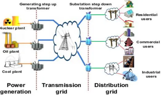
In current electrical grids, the electricity is produced in large power plants. There is a spinning electrical generator that rotates using, in most cases, a steam turbine. The steam can be created by burning coal, oil, natural gas or by nuclear combustion. The power leaves the generator and goes into a transmission substation at the power plant where the voltage of the electric power is increased using large transformers. This higher voltage allows the transmission for long distances on the transmission grid. In order to be useful in private homes or factories the voltage needs to be stepped down to the distribution grids. This process takes place in a small power substation which is composed by transformers, a bus that split the distribution power off in multiple directions, circuit breakers and switches. The power leaving this substation enters the distribution grid. When the power arrives to the service location the voltage is reduced again to be used in homes and facilities [4]. In Fig 1, it is represented an example of the traditional power grid.
20 Figure 1 - Traditional Power Grid.
These are the main infrastructures used in the traditional electric grid. The SG´s infrastructures can be divided in power generation, transmission grid and distribution grid too. However the electric energy generation and the flow pattern are more flexible since it is a two-way communication.
3.2.1 Power Generation
The power generation process used nowadays comes from 1830 when Michael Faraday, a British scientist, discovered that the motion of a loop of wire or a disc of copper between the poles of a magnet can generate electricity.
Until a few years ago this process relied mostly in fossil fuels to produce electricity. However the use of renewable sources is increasing due to environmental and economic problems related with fossil fuel combustion.
In SG, there are two concepts related to power generation. First, there is DG which takes advantage of distributed energy resource (DER) systems to produce electricity. This is only possible because SG allow the two-way flow of electricity and information. The other important concept is called Virtual Power Plants (VPP) which manages a large group of distributed generators.
The DG can loosely be defined as a small-scale electricity generation. It is a set of small sized electric power generating units at or near a consumer. It is possible to say that DG is
21 referred to power generation at the point of consumption. This fact allows cost reduction, complexity, interdependencies and inefficiencies associated with transmission and distribution.
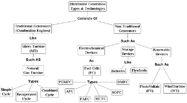
There are different technologies that can be used for a small-scale electricity generation as shown in fig.2 [5].
Figure 2 - Types of DG technologies.
Unfortunately with a high number of DER there are some challenges that need to be surpassed such as the intermittence of renewable sources which are weather dependent, their fluctuating output is considered non-dispatchable. Furthermore, the DER units working isolated due to different ownerships make their capability restricted to satisfy the local needs but not the whole grid.
There is a way to address these issues which is aggregate a number of generation units in a VPP. All the DG generators will be managed by the VPP that can be defined as a cluster of dispersed generator units, controllable loads and storage systems, aggregated in order to operate as a unique power plant. The VPP has an energy management system that controls the power flows coming from the generators in a two-way communication which means that the VPP not only receive the information coming from the generation systems in terms of current status, but it can also send signals to control the objects. This feature is very interesting because the VPP can operate to accomplish different objectives such as minimize the generation costs, reduce emissions or maximize the profit [6]. In fig.3, it is given an example of a VPP structure.
22 Figure 3 - VPP Structure.
It is possible to consider VPP as a way to integrate different DER into SG’s framework in both technological and market/commercial terms. VPPs are classified as Technical (TVPP) and Commercial (CVPP). The TVPP ensures that the power system is operated in an optimized and secure manner, taking physical constraints and potential services offered by VPP. The CVPP considers DERs as commercial entities offering the price and amount of energy that it can deliver, optimizing the economical utilization of VPP portfolio for the open electricity market. The purpose of the CVPP is to schedule and optimize DERs utilization taking into account the energy offers and needs, while the TVPP manages the operational employment of particular DERs in technically wise [7].
The way in which the communication is done between the VPP and the DER systems will be explain next in the management and communication infrastructures sections. The objective of this section was only to provide the basic concepts and infrastructures behind the power generation in SG because it is completely different from the traditional way.
3.2.2 Transmission Grid
The electric transmission grid has evolved since it was created. It started with local low DC voltage networks to high voltage with three phases and finally interconnected networks with various levels of voltage and complex components. It is important to have these concepts in mind reading this work. It is important to implement fast online analysis tools, wide-area
23 monitoring, measurement and control in order to satisfy the energy demand and improve the reliability of networks [8].
An electric transmission grid is the fundamental part to deliver electricity from the generation points to end consumers. In SG it has to satisfy new needs related to environment, market and infrastructures. This is why the new smart transmission grids must follow a different path from the traditional ones, which contributed largely to climate change and other issues. These objectives are accomplished with new technologies and materials.
The smart transmission grid is composed by a digital platform in order to allow a fast awareness and reliable sensing, measurement, communication, control, protection and visualization and maintenance of the entire transmission system. It must be flexible so it is possible to expand to future developments. The state of operation knowledge is important to allow a self-healing and the interoperability of the system.
The smart transmission grid is composed by three parts: control centers, transmission network and substations.
The idea behind the smart control centers is based on the existing control centers adding them new functions such as monitoring, analytic capability and controllability. The current monitoring process is done through estimators that are based in collected data via Supervisory Control and Data Acquisition (SCADA) and Remote Terminal Units (RTU) but in SG this information is collected by state measure modules which are more efficient. This equipment will be studied in detail in the information subsystem. The results from state measurement will be combined with Geographical Information Systems (GIS) for visual display on control center screens in real time.
The smart transmission networks in SG are expected to be more efficient and safe than the current ones. In SG, the transmission in long distances is done using high capacity AC and DC facilities. New transmission lines with 6 or 12 phases improve the transmission with reduced electromagnetic fields. The reliability and flexibility will be accomplished with Flexible AC Transmission Systems (FACTS) and High Voltage DC (HVDC) devices. These technologies relieve transmission congestions. HVDC are widely used lines to provide a controllable and economic alternative to long distance AC lines. Finally, the smart transmission network is composed by solid-state components such as transformers, circuit breakers and other devices that offer better reliability and life span.
The smart substations must provide monitoring, operation, control, protection and maintenance on the equipment installed there. From an operation viewpoint these substations must digitalize all the tasks. The operator should be autonomous but coordinated with other
24 substations. The traditional electromechanical Current Transformer (CT) and Potential Transformer (PT) will be replaced by optical CT and PT which allow wide bandwidth, high accuracy of measurement and low maintenance costs. Each substation has its own Local Area Network (LAN) and a communication network via router to connect all the substations [8].
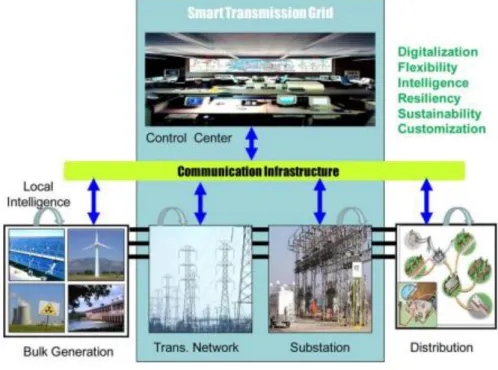
The smart transmission grid can be seen in fig.4. In this figure it is possible to see how it is correlated with the other infrastructures in the SG.
Figure 4 - Smart transmission grid topology.
3.2.3 Distribution Grid
As it was stated before the power generation in SG will be distributed using many renewable sources. This means that the households won’t be just consumers but producers too. This fact comes with many benefits but it has a problem related with the balance between what is produced and demand which requires regulated renewable energy production. To solve this, it will be used in-home distribution systems that allow reduction on energy consumption and balancing production with demand, in every home [9]. There are two systems that can be used in SGs.
The first one is a circuit switching system based on AC power distribution. The goal of this system is to concurrently deliver electricity via single power distribution network in-home when renewable sources are installed in addition to commercial power. It is known that the
25 quality of the energy produced by renewable sources is worse than the one that is commercialized nowadays, this is why batteries are coupled to this distributed systems, to compensate the fluctuation. On top of that, it is necessary to use convertors and invertors to match the quality of the commercial power. However, there are some devices with incorporated batteries that do not require high quality energy, so it is acceptable to directly connect a load to a source depending on what is necessary. To accomplish this source-and-load matching, quality and the amount of generated power must be known. To overcome this obstacle, it will be used Power Line Communication (PLC). The system is composed by two components: an information terminal and an AC power router. Each one of these components has a PLC modem and a microprocessor (CPU) with a Linux operating system. The information terminal gathers all the information from sources and loads. The CPU decides what the best source for a certain load is and transfers it to the router [10].
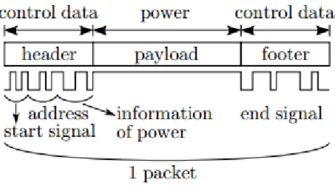
There is another distribution system that can solve the problems stated above. It is a packet dispatching in DC distribution system that uses power packets, represented in fig 5, through transmission IP-based Networks.
Figure 5 - Power packet representation.
Power packet representation.This system is composed by multiple sources and loads, each one with an individual address, a mixer, a router and a single distribution line connecting the mixer and the router, as it is possible to see in fig 6. Supplied power from sources is divided into several units of payload that are attached with a header and a footer forming a power packet. The header is composed by a start signal that marks the beginning of the packet, the load and the sender addresses. The footer has the end signal. The amount of energy per packet is regulated switching the length of the payload. A power request to a certain address is given when the payload is empty. The function of the mixer is to gather the payloads and send them to the distribution line, the router receives the packets the controller sorts them according to the addresses on headers and sends them to loads [10].
26 Figure 6 - Packet Dispatching System.
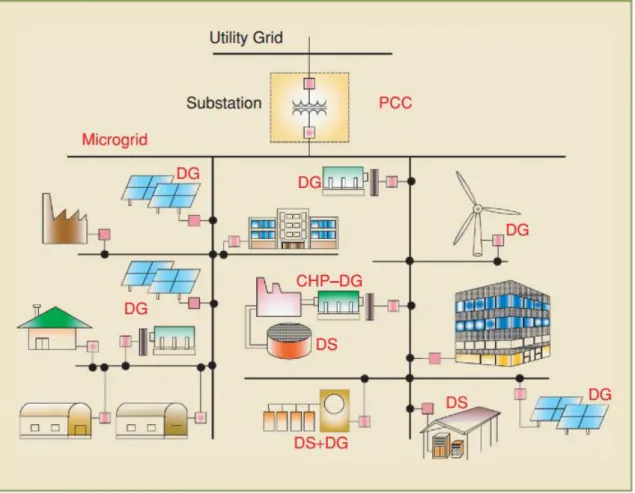
3.2.4 Microgrid
One of the cornerstones of the SG is the new paradigm called microgrid which development is promoted by DG. A microgrid is a group of electricity generation, energy storage and loads that is connected to a traditional centralized grid (macrogrid).
A microgrid can be a part of an intelligent global electric power and defined as an extension to the distribution grid, being located downstream of the distribution substation and formed by DER, different type of electricity and/or heat consumers. The DER units on the microgrid englobe DG and DS (Distributed Storage) which have different characteristics and capacities depending on loads and energy usage on that system. DER units are divided into two groups depending on their interaction with the microgrid. Thus, they can be connected through rotating machines or through electronic converters to provide a connecting media with the system. Control and operation strategies of the two groups of DG and DS are completely different from each other. For this reason, control strategies and dynamic behavior of a microgrid is very different from the conventional power system, especially in islanded mode. Furthermore, control strategies and energy management are dependent on the type of DER, load requirements and operation scenarios expected, in contrast with pre-defined and well stablished strategies in grid-connected mode [11]. Figure 7 shows the components and a general architecture of a microgrid.
27 Figure 7 - Microgrid Architecture.
3.2.5 Renewable Energy Sources
The International Renewable Energy Agency (IRENA) launched a roadmap for renewable energy, in 2012. The objective was to double renewable share in global energetic mix until 2030, going from 20% to 40% in that period of time.
In developed countries, the best way to increase the renewable share is to transform the electric sector through updates and modern extensions. That modernization is technically possible and must provide new solutions to accommodate different types of renewable generation. In particular, SG is capable of incorporate characteristics of this type of generation, such as, variability, DG and high initial cost. As it is known, some renewable depend on external conditions, such as weather, to produce electricity. However, production must always meet demand and that is why it is necessary that the system absorb this variability. Furthermore, renewable generation has a high investment cost than other generation technologies. Although renewables are cost-effective in some situations, particularly in developing countries, there is not enough investment in them.
28 The SG can address these three challenges and offer additional benefits facilitating the transition to renewables. In this section, it will be seen how it can be accomplished.
Starting with variability, SG can integrate renewables with a great variability of resources. For example, imagining a PV system and a set of industrial and commercial users on an interruptible rate, all tied together with SG communication and control technics. If the PV system drops due to a cloud, the SG stops the service to those consumers in the interruptible rate, because this is a rate in which service can be interrupted without penalty. When the cloud passes, the service resumes.
Relatively to DG, the advantages of SG were already exposed in this work, so it is already know that SG can help developing this type of generation.
Finally, SG is able to address capital requirements encouraging private investment in DGs. Traditionally, electric utilities are the ones with the responsibility to invest in power plants to produce electricity but with the increase of DGs any person or organization can invest in energy generation systems. SG allows this, enabling utilities to manage and incorporate many small and/or individual plants in the electric system. In a more radical vision, in which the SG is compared to the Internet, where governments had the responsibility to provide the grid, nowadays, the private sector is the one providing that service [12]. In this vision, the generation almost all distributed, the consumers could be able to make direct market, bilateral deals with producers and the utility paper is relegated to distribution only.
3.3
Data Management Infrastructures
The SG not only relies on advanced generation equipment but also in the improvement of sophisticated monitoring, analysis, optimization and control from the generators location to the transmission and distribution grids. Some aspects such as interoperability of data exchanges should be addressed from a management technology perspective. The data management system is used to support generation, modelling, integration, analysis and optimization in the context of the SG.
In this section, this system will be demonstrated such as the infrastructures and devices which generate information from each entity in a SG. This equipment can be classified as information metering and measurement. The information provided by the previous devices is very important and is used for many purposes that will allow a better operation of the whole SG.
29 Finally, it will be explored the data management infrastructures that allow data modelling, information analysis, integration and optimization of the gathered information.
3.3.1 Metering and Measurement
The smart metering is a mechanism that must be used in SG to control behaviour and obtain information form users’ devices and appliances. An advanced metering infrastructure (AMI) system is regarded as a logical strategy to realize SG. This system is built upon automatic metering reading (AMR) which is the technology of automatically collecting diagnostic, consumption and status data form energy metering devices and transferring that to a central database for billing, troubleshooting and analysing. As it goes for every component in SG, AMI differs from traditional AMR because it enables two-way communications with the meter. This meter can provide information in real time and on demand allowing system operations and customer power demand management.
The equipment that will allow the smart metering is the smart meter which is an electronic device capable of providing consumers, suppliers, distribution network operators, generators and regulators a wide range of useful information allowing new energetic services and contracts.
Traditionally, the energy consumption in households is measured by electromagnetic devices called Ferraris meters. Basically, these meters are composed by an aluminium disk that spins in a magnetic field with velocity proportional to consumption. Even though, Ferraris meters are robust, reliable and cheap they require human intervention to collect, communicate and store the information. Furthermore, it is not possible to gather detailed information such as the energy consumption in a certain hour in a specific day. Finally, these meters are not able to register electricity interruptions or deviations in nominal voltage and do not allow acting upon consumption.
The smart meters are more accurate than the electromagnetic ones, have low energy consumption and can be combined with digital displays and electronic local storage units that provide a better knowledge to users about their consumption. With these meters it is easier to monitor different variables like reactive power or power factor. These variables can be used to improve consumers’ behaviours, redefine tariffs and define new incentives/penalties. The benefit of smart meters reaches everyone from consumers to suppliers. The consumers will be able to manage their consumption, save money and get a better quality of service. The suppliers will have more pricing options, less complains on billing and a better management on their
30 portfolio. The distribution network operators will be able to quickly identify fault locations, faster restore and an improved detection of network losses and theft. There are still benefits to the public interest such as energy efficiency, increased penetration of renewable energy and improved security of supply [13].
3.3.2 Monitoring and Measurement
Another important function in SG vision is the monitoring and measurement of grid status. The most important equipment is the sensors and phasor measurement units (PMU).
Sensor or sensor networks have been used as an approach to monitoring and measurement in different applications, in order to detect mechanical failures in power grids such as conductor failures, tower collapses, hot spots and extreme mechanical conditions. Wireless Sensor Networks (WSN), in particular, due to its lower cost is able to provide feasible and cost-effective communication and sensing platforms to remote monitoring and diagnostic [14].
In traditional electric systems, plant evaluation is realized through wired systems formed by communication cables and sensors. This architecture is expensive to install and maintain since cables are even more expensive than the sensors. So, it is logic, that a way to lower these monitoring system costs is to eliminate communication cables adopting a wireless structure for this purpose. However, before WSN appear in recent years, these systems were very expensive. The deployment of wireless communications allowed a large scale integration of multifunctional sensors and actuators, which resulted in WSNs deployment. WSNs characteristics, including a sensor-rich environment, high reliability, self-organization and inherent intelligent capability make them ideal structures to a low cost management to achieve a better planning decision. In these systems, wireless multifunctional sensor nodes are installed in critical equipment of SG, which monitors critical parameters to each equipment conditions [15]. Potential applications of WSN in SG vary from Wireless Automatic Reading (WARM) to remote system monitoring and equipment fault diagnosis.
WARM systems offer many advantages to electric companies, including, reduced operation costs associated with the fact that there is no need for human presence on reading and pricing or for asset protection through advanced remote monitoring [16].
In the current electric system, safety and reliability are considered the most important characteristics once system breakdowns caused by different factors, such as, component failures, environmental aspects or bad operation can cause huge economic losses and public
31 concern. It is known that these system breakdowns can be, relatively easy to avoid or at least be alleviated if the components and protection devices were better monitored and coordinated which does not occur nowadays. This happens because existing solutions are very expensive to be applied in large scale. For this reason, WSNs being considered a cheaper offer can be a good solution to this problem. The efficient equipment monitoring in SG, through sensor nodes provide complete information on component conditions, like generation units, transformers, transmission lines and motors in a remote manner. Using an online monitoring system it will be possible to detect and isolate a system contingency and avoid cascading effects.
There are some technical challenges imposed by SG applications that WSNs must overcome. In any electric system, there are harsh environment conditions, such as highly caustic or corrosive conditions, high humidity levels, vibrations or dirt and dust, making sensor nodes to malfunction or produce obsolete information. Another challenge is related with reliability and latency requirements because there are a wide variety of applications in SG having different specifications in terms of reliability, latency and network throughput. Finally, there are resource constraints, since the design and implementation of WSNs are constrained by three types of resources which are energy, memory and processing. In general, sensor nodes have limited battery energy supply. This is why communication protocols for WSNs are mainly tailored to provide high energy efficiency [17].
Blackout occurrence in the majority of electric systems originated the deployment of PMUs and Phasor Data Concentrators (PDCs) in a hierarchical structure. Data provided by PMU is accurate and allow a complete analysis to realize the event that cause blackout, help analysing sequence of events to determine their exact causes and malfunctions present in the system. This is the main application of these devices, nowadays, but with the deployment of Wide Area Measurement System (WAMS), new applications have been discovered, highlighting system monitoring, protection and control [18].
Traditional monitoring systems rely on RTUs and state estimators in SCADA system. RTUs measure voltage and current Route Mean Square (RMS) values of the bus where it is connected. Measured values are sent to state estimators in the Main Control Center (MCC) so that the phase angle and power flow values get computed. However, these state estimators are slow which cause delay to occur during calculations. Furthermore, state estimators are vulnerable to several errors thanks to weal modelling of traditional power electric systems. For these reasons, it is important for SG to have an improved monitoring system. For that, PMUs must be used. These devices, when placed on buses measure voltage phasor values (magnitude and angle). Yet, it is possible to know currents flowing through all branches connected to that bus. Measured values are then sent to a GPS which allows the synchronization of the measured
32 electric quantities in every PMUs connected in the power grid. Since the voltage and current phase angles are directly measure in all buses it is possible to get a better state estimation using PMUs [19].
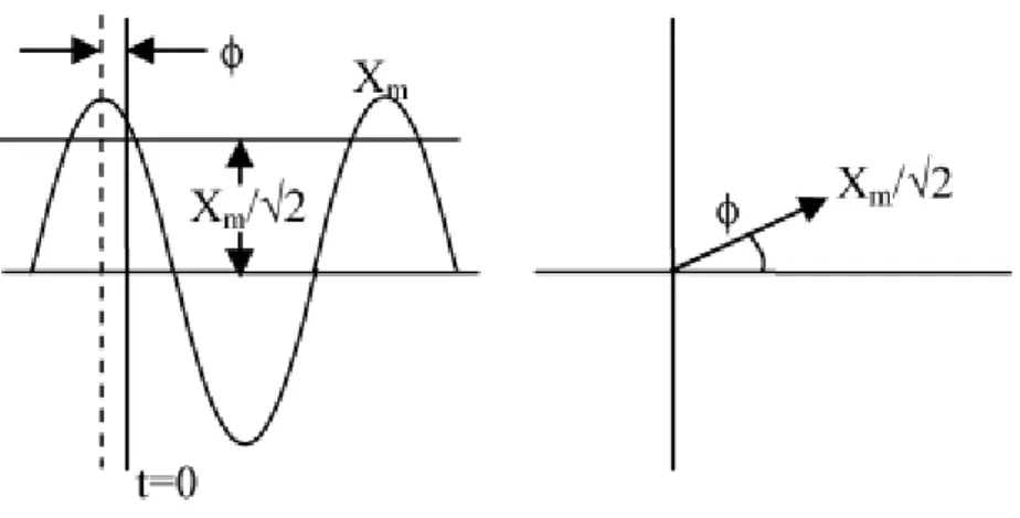
A phasor is a complex number that represents magnitude and phase angle of an alternative quantity which, in this case, it is sinusoidal waveform representing electricity. The phasor module is the peak or RMS value of the waveform. The sinusoidal waveform and the respective phasor are represented in fig.8.
Figure 8 - Simple sinusoidal waveform and its phasor representation.
PMU is a digital device capable of measure voltage and current phasor values with respect to a global time reference. Function diagram of PMUs can be seen in fig 9.
Figure 9 - Function block diagram of PMU.
The analog signals inputs from transformers enter directly in the anti-aliasing filters without using any kind of interface. Anti-aliasing filters restrict the signal bandwidth in order to satisfy the sampling theorem. The output signal coming from the anti-aliasing filters are converted to digital values using analog to digital converters (A/D converters). Phase locked
33 loop assure that sample synchronization with the reference signal of GPS. Converted signals are, then, fed in the phasor microprocessor where the phasor values are estimated using Discrete Fourier Transform (DFT). These computed phasor values are incorporated in a current message and sent via communication network to the WAMS. The synchronization provided by GPS signals assure that the measurements of all PMUs are done at the same time.
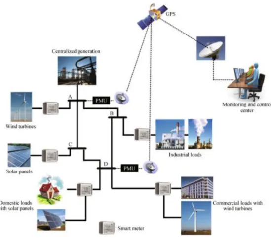
PMUs allow SG to have a more efficient and accurate monitoring system operation. The measurements from these devices allow an easier and faster power value calculation than in the traditional electric system based on state estimators. In fig. 10, it is possible to verify the link between GPS, smart meters, DGs and control centers to form a metering and measurement structure. In this case, there are four buses but it is only needed two buses for a complete monitoring of the system [19].
Figure 10 - Example of a four bus SG representation.
In order to find this optimal placing of the PMUs which objective is to find the minimum number of these devices to monitor the entire grid, it can be used the Integer Linear Programming (ILP). This mathematical optimization method allows having an optimal outcome for a given mathematical function subjected to some restrictions. The goal of placing PMUs is that every bus gets reached by at least a PMU. For this placing to be done efficiently it is necessary to have a communication system in each bus to transfer data from PMUs [19].
34
3.4
Communication Infrastructures
In previous sections it was already explored some of the infrastructures and equipment that will be used in SG. Now, the focus is the communication infrastructures which are responsible for the connectivity between all the systems, devices and applications that were identified before.
The communication system is a key component of the SG infrastructure. There is a huge amount of data from different applications that will be generated and it is necessary to analyse and control it because of the integration of advanced technologies and applications to achieve a smarter electric grid. This means that is crucial to define the communication requirements and find out the best communication infrastructure to realise all the SG´s objectives since there are various technologies that can be used.
There are some requirements that a communication infrastructure need to follow. As it was stated before, energy generation, transmission and distribution requires two-way communication, inter-operability between advanced applications and end-to-end reliable and secure communication with low-latencies and sufficient bandwidth. Moreover, this system must be secure in terms of cyber-attacks and system operability. Finally, the communication system must be scalable. This means that the system must be able to easily accept the new smart meters, smart sensor nodes, smart data collectors and renewable energy resources joining the communication network.
The communication technologies are divided into two groups: wireless and wired. Some of these technologies will be described in this section but before that, it is important to establish objectives and requirements that they must follow to be considered applicable in SG. These requirements are important since there is a great debate related with the specific technology that must be used in each SG application domain. However, there is a general agreement on the need for a communication network capable of supporting a two-way information flow between the different entities in the electric grid. Furthermore, there are some requirements that are consensual and should be taking into account for communication systems used in SG. The most important one is the quality of the service because there is critical data that must be delivered promptly. The system must be highly reliable, but since there are a great number of devices connected, this task is hard. Moreover, the system must be pervasively available and have a high coverage so it will be able to respond an event anywhere in the grid, in time. Finally, it should guarantee the security and privacy, factors that will be studied ahead [20].
35 With these requirements in mind, it is now possible to describe some of the communication technologies and infrastructures which are applicable in SG.
3.4.1 Wireless Technologies
Wireless technologies are present on our quotidian. Some of them are already used for electric system automation.
These communication technologies offer a great number of advantages over the wired ones. Some of them are the lower initial installation cost, rapid deployment and mobility which make these technologies more suitable for remote application. However, these technologies are more susceptible to Electro Magnetic Interference (EMI), offer limitations in bandwidth capacity and maximum distances among communication devices and there is the possibility to occur eavesdropping which can threaten communication security since radio waves in wireless communication spread through the air.
There are two ways to explore this kind of technology. The first one is using an existing communication infrastructure of a public network. The other is to install private wireless networks.
In this section, it will be explored the most important wireless communication technologies, their advantages and disadvantages, their architecture and their possible applications.
- Wireless Mesh Network (WMN)
A wireless mesh network is one of the most important technologies since it has many advantages over the other wireless networks.
WMNs are composed by two types of nodes: mesh routers and mesh clients. As any conventional router, mesh routers have gateway/bridge capability, but they have other characteristics essentials to support mesh networking. Through multi-hop communication it is possible to achieve the same coverage with a mesh router with low transmission power. Furthermore, a mesh router is equipped with multiple wireless interfaces which improve the flexibility of mesh networking. Despite these differences the hardware used in mesh routers and conventional ones is similar. All these advantages bring benefits to WMNs such as low up-front cost, easy maintenance, robustness, reliability and better service coverage.
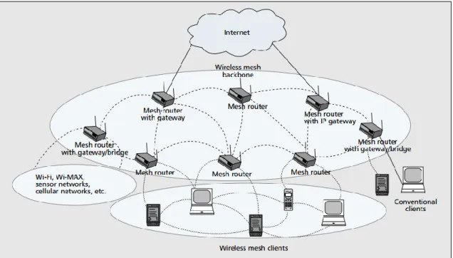
36 There are different architectures that can be adopted to realize WMN. Here, it will be explored the one with more advantages which is called hybrid WMN and is shown in fig 11. The mesh clients can access the network through mesh routers as well as directly meshing with other mesh clients. While the infrastructure composed by mesh routers provides connectivity with other networks like Internet, Wi-Fi, WiMax, cellular and sensor networks, the routing capability of mesh clients provides higher connectivity and coverage in WMN. The infrastructure can be built using different types of radio technologies. The mesh routers forming this infrastructure are auto-configurable and self-healable. The gateway functions of mesh routers allow this network to be connected to the Internet. The bridge function permits the WMN integration with existing wireless networks. The conventional mesh clients can connect to mesh routers via Ethernet links. The ones which have their own mesh routes can connect directly to the infrastructure and communicate with it. If different radio technologies are used, the mesh clients must communicate with their base stations which have Ethernet connection with mesh routers [21].
Figure 11 - Hybrid Wireless Mesh Network architecture.
Summarizing, WMNs bring many advantages to SG such as increased communication, reliability and automatic network connectivity, since it is self-organized and self-configured. Furthermore, these networks enable both long distance and high data rate communications. In SG there is a large amount of data coming from smart meters, sensors and PMU’s which require a large coverage and high data rate communication network.
37 -Cellular communication systems
Existing cellular networks are a good option for communication in SG too. This is a solution that is very interesting because it is not needed to build a new communication networks since it is possible to use the existing ones owned by communication service suppliers, preventing utilities from spending operational costs and additional time for building a dedicated communication infrastructure.
The network topology consists in cells formed by multiple wireless power transmitters. Data travels from cell to cell without any interruption, forming a point-to-point architecture. This infrastructure is able to receive data via Ethernet and transmitting it through the cellular network allowing wired devices to become wireless. This technology offers high coverage and no maintenance costs since it is used by service communication suppliers.
Cellular network characteristics are perfect for monitoring and metering remote DER but it is a good option for communication between smart meters and the utility which can be achieved by using 2G, 3G, 4G, WiMAX and LTE technologies. This is possible using a SIM within a cellular radio model integrated in smart meters [20].
This communication system has a lot of advantages. Some of them were already exposed like the fact that an initial investment in infrastructures is not required. But there is more. Due to data gathering at small intervals, a huge amount of data is generated requiring high bandwidth to transfer it which is no problem for cellular networks. In terms of security, this system is ready to secure data transmissions with strong security controls. Other advantage is related with the fact that the use of mobile phones brought the need to increase the coverage of cellular networks and nowadays the infrastructures coverage reaches a really wide area. All these advantages highlight cellular networks as a good candidate for SG applications such as demand response management, advanced metering and outage management.
However, there are some disadvantages that need to be considered. The services of cellular networks are shaped by customer market which can result in network congestion or decrease in network performance. This effect can be really important if it is considered that some applications in SG need continuous availability of communications. Another problem that must be considered is that sometimes cellular network providers may not provide guaranteed service, which normally happens when there is some kind of natural disaster [16].
-Satellite Communication
The satellite communication offer interesting solutions for remote control and monitoring on substations. This technology is a good alternative to cellular communication