385 Ralph Werner Heringer Oliveira
Doutorando em Geotecnia de Pavimentos Universidade Federal de Ouro Preto – UFOP Núcleo de Geotecnia - NUGEO
Escola de Minas
Ouro Preto – Minas Gerais - Brasil [email protected]
Gilberto Fernandes Professor
Centro Universitário do Cerrado Patrocínio - UNICERP Patrocínio - Minas Gerais – Brasil
Fabiano Carvalho Sousa Engenheiro da Vale
Belo Horizonte – Minas Gerais - Brasil [email protected]
Rairane Aparecida Barreto Aluna
Graduação em Engenharia Civil
Universidade Federal de Ouro Preto – UFOP Escola de Minas
Ouro Preto – Minas Gerais - Brasil [email protected]
Chemical and mineralogical
characterization of silicon
manganese iron slag as railway ballast
Abstract
In nature, metal ores such as iron, lead, aluminum and others are found in an im-pure state, sometimes oxidized and mixed with silicates of other metals. During casting, when the ore is exposed to high temperatures, these impurities are separated from the molten metal and can be removed. The mass formed by these compounds is slag. Slag is the co-product of the smelting of ore to purify metals. It may be considered a mixture of metal oxides, but may also contain metal sulphites and metal atoms in their elemental form. After it is reprocessed to separate the metals contained, the co-products of this process can be used in cement, rail ballast, road paving and various other purposes. The objective of this research work is the presentation of the chemical and mineralogical char-acterization tests of the silicon-manganese iron slag with the purpose of reusing the co-product as rail ballast. X-ray diffraction tests, quantitative chemical analyzes, scanning electron microscopy and free lime content were prepared for these characterizations. The results of these tests showed the technical feasibility of using slag as rail ballast.
Keywords: alternative ballast; Silicon-Manganese Iron Slag (FeSiMn); environmental
characterization and classiication.
http://dx.doi.org/10.1590/0370-44672017700019
Civil Engineering
Engenharia Civil
1. Introduction
Ferroalloys are essential inputs in the steel industry, as they are indispensable in the manufacture of all types of steel, both in the basic processes and in the reined property and value aggregation in special steels (Andrade et al., 1999). Basically the most conventional ferroalloys are ferro-silicon, ferrochromium, ferro-silicon-manganese and ferroferro-silicon-manganese, and are present in almost all the processes of iron and common or special steel production.
Among the types of alloys, the most prominent in their production are the manganese alloys. They are applied in the manufacture of virtually all types of steel and iron castings due to their desulfurizing and deoxidizing properties (Andrade and Cunha, 2000).
The production process of the silicon-manganese iron alloys (FeSiMn) consists of
the simultaneous reduction of manganese and silicon by carbon in electric reduction furnaces (FER). The charges consist of manganese ore and quartz (or quartzite) or manganese ore, rich slag and quartz (or quartzite). These charges are comple-mented by luxes and reducers, which are used to adjust the composition of the steel co-product (slag) in the process.
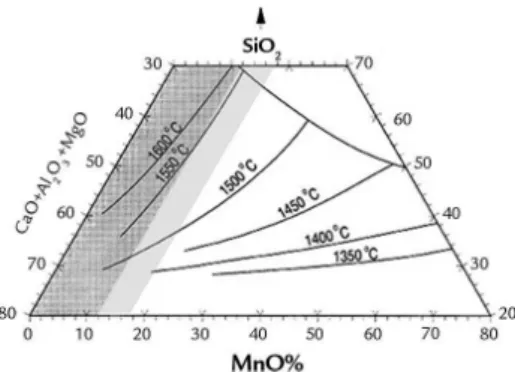
According to Olsen and Tangs-tad (2004), the distribution of Si be-tween SiMn alloys and multicomponent MnO-SiO2-CaO-Al2O3-MgO slags is mainly determined by the process tem-perature. The silicon content from silica will increase by approximately 6 % per 50 °C in the temperature range from 1550 °C to 1700 °C. This process is only feasible if the reduction temperatures of both oxides are close to each other.
An-other aspect to consider is the melting point of the slag: if it is below the silica reduction temperature, the furnace will continuously spend energy in melting, to the detriment of the reduction reaction.
system. The equilibrium relationships between the two systems for the Carbon
Monoxide (PCO) pressure equal to 1 atm are shown in Figure 1, which shows the
diagram of the system considered (Ding and Olsen, 2000).
Figure 1
Diagram of metal-slag-gas
equilibrium (Ding and Olsen, 2000).
There are several proposed equilib-rium relationships for these systems. Each refers to existing conditions, whether in statistical data of one or several installa-tions, or in speciic experiments.
There are two types of slag formed by the described production processes: the
rich slag, which is acidic, presents high Mn contents (above 40 %), being recyclable and reused as an input in FeSiMn production (besides having very low phosphorus con-tent, which is an advantage for the FeSiMn production), and poor basic slag, which has low manganese content (MnO < 20 %) and
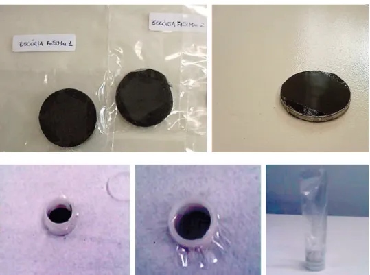
about 30 % of Si is produced by upgrad-ing the standard alloy through addition of silicon waste from the iron silicon in-dustry, which at the end of the ferroalloy production process, is discarded (Olsen and Tangstad, 2004). Figure 2 shows the silicon iron manganese slag.
(a) (b)
Figure 2
Silicon-manganese
iron slag (a) rich and (b) poor.
The use of slag as a base material for pavement layers and as a rail ballast has been
researched by other authors, Silva (1991); Kandhal and Hoffman (1998); Bagampadde
et al. (1999); Rohde (2002); Fernandes (2005); Nóbrega (2007); Fernandes (2010) and others.
2. Materials and methods
As mentioned earlier, there are two types of slag formed by the described production processes: rich and poor slag. The rich slag is acidic, because it contains high levels of Mn, undergoes vitriication that decreases its resistance and makes it dangerous for handling. This high content of Mn contained in the rich slag is reused as an input in FeSiMn production. Thus, because it is a basic co-product with low manganese content, has a resistance greater than that of the rich slag and is
not being reused in the production of FeSiMn, the silicon-manganese iron slag used for this study was the basic (poor) slag. For that, slag samples provided by a silicon-manganese iron producer in Minas Gerais, at its Ouro Preto-MG unit, were used, which has a production capacity of 5000 t / month, with 3000 t / month of material processed for use as a rail ballast. The sample of the material was initially subjected to X-ray diffraction, quantita-tive chemical analyses, scanning electron
microscopy and free lime content assay. For the accomplishment of these tests the material was submitted to the granulometric reduction process. It was then sieved, where approximately 20 kg of the sample passed through a sieve of either 200 or 75 μm. All the tests have as reference the standards established by ABNT (Brazilian Association of Technical Standards), AREMA (Ameri-can Railway Engineering and Mainte-nance Association).
X-Ray Diffraction Analysis
A Shimadsu diffractometer, model D / MAXB, with iron tube and scan-ning range of 7° to 70° and radiation of 20 kV and 5 μA was used in the analy-sis. The speed adopted in the test was 2 degrees / minute lasting ± 35 minutes.
The analysis of the results is processed through speciic software (MDJ Jades), which compares the peak of the in-cidence of electrons with a database available for the characterization of the constituent minerals.
A monochromatic X-ray radiation was imposed on the samples under vari-ous angles of incidence. The dispersion of the different wavelengths obeys Bragg’s law which is represented by the Equa-tion below:
n
l
= 2dxsen
q
Being: n - integer known as the order of
the diffracted beam; l - wavelength of the
apparatus tube; q - incidence angle and
387
The records of this optical process are collected in a detector in the form of an ampliied electrical signal, which is recorded in digital or analog form,
cor-responding to the diffractograms. The dif-fractograms present characteristic peaks that are the results of X-ray diffraction in crystallographic planes of the sample,
related to the position, intensity and shape of the crystalline structure, thus character-izing the mineralogical composition of the analyzed materials.
Quantitative chemical analysis
It is by measuring the intensity of the characteristic X-rays emitted by the sample’s elements that the quantitative analysis by X-ray luorescence is based on. A radioactive source emits X-rays, which excite the constituent elements and, in turn, emit spectral lines with characteristic energies of the element and whose intensities are related to the concentration of the element in the sample. X-ray fluorescence analysis consists of three phases: excitation of the sample elements, dispersion of the characteristic X-rays emitted by the sample and detection of these X-rays emitted. The X-ray luorescence
spec-trometer is an instrument that enables the quantitative determination of the elements present in a given sample by applying X-rays to the surface of the sample and the subsequent analysis of the luorescent rays emitted.
In the analysis, a Shimadsu Energy Dispersion X-ray spectrometer, model EDX-700 HS / 800 HS / 900 HS was used. The samples used in this experi-ment went through two types of prepa-ration: The irst preparation was carried out with 20 g of pulverized sample passed through the 75 μm sieve. Then the sample was heated between 100 ° C and 120 °C in the furnace, after which
0.6 g of estuary acid - C18H36O2 (acts as a 'glue' to ix the sample) were added. Next, the sample was further sprayed for 4 minutes to mix the sample mate-rial with the estuary acid, and then the mixture was pressed into the pallet form. In the second preparation, 10 g of pulverized sample was passed through the 75 μm sieve, and then the sample was placed in a plastic ring sealed by a plastic ilter and inserted into another plastic bag with the tips cut to form a vacuum in the sample for the test. Samples prepared for the X-ray luores-cence assay are shown in Figures 3 and 4 for the irst and second assemblies.
Figure 3 Samples prepared in the first assembly for the assay.
Figure 4 Samples prepared in the second assembly for the assay.
Chemical analysis by scanning electron microscopy
For the observation and distinc-tion of different types of minerals stemming from the emission and inter-action of electron beams on a sample, the Scanning Electron Microscopy technique was used, which allows the characterization from the point of view of its morphology, its organization and its chemical composition. What is observed in the scanning electron microscope is due to the contrast variation, which occurs when a primary electron beam sweeps the surface of the sample in point-to-point analysis. The
qualitative distinction of the particle morphology of the samples of the study materials was made using an electronic scanning electron microscope of the JEOLJSM-5510 type.
In the test, the samples need to be conductive in the presence of carbon and, for this, they undergo the metal-lization process. The samples are thus arranged in the form of monolayers in metal cylindrical pieces (pallets), coated with graphite by a double-sided tape, then deposited in a vacuum evapora-tor for a period of about 1 hour. The
Free lime content
In determining the free lime con-tent, the test method prescribed by NBR NM 13/2004 - Portland Cement - Determination of free calcium oxide by ethylene glycol (ABNT) was used as reference. This standard speciies the determination of free calcium oxide by dissolution in ethylene glycol and subsequent titration in standard solu-tion of hydrochloric acid (HCl) using
a mixture as a pH indicator (mixed indicator solution).
For the assay, three samples con-taining 1.00 g each were weighed and mixed in three capped Erlenmeyer lasks, each containing 30 ml of cor-rected (green) pH ethylene glycol. The flasks were then heated in a water bath at 65 °C to 70 °C for 30 min, shaking the flask every 5 minutes.
After this process, the iltration was done with a slow iltration ilter and a vacuum pump. Thereafter, the iltrate is transferred to a clean lask and 3 to 5 drops of mixed indicator solution are added. Then the above solution is titrated with 0.1 mol / l HCl until it changes from green to pink. Thus, the formula below is used to calculate the free lime content:
Where, F - HCl Factor; M - Mass of crushed sample employed in the test; V - Volume of HCl used in the titration.
m
0.002804
V
F
CaO
free
×
×
=
This method does not differenti-ate oxide [Ca (OH)] from hydroxide [Ca (OH)2] and does not determine the calcium that is chemically combined in solid solution with FeO and MnO or in
the form of silicates. However, in the scope of the analyses intended in this study, the results of this test are more than satisfactory. They serve as a basis for estimating the percentage of free
lime, which causes the expansion that is responsible for causing the spontaneous breaking of the grains, which in turn causes the excess of ines that is harmful to the ballast.
3. Results of tests and discussion
Since there is no speciic technical standard for silicon-manganese iron slag both in Brazil and abroad, the values found in the analyzes were compared
with the indexes recommended by AREMA (2001) for LD steel mill slag. In order to use the LD steel mill slag ballast, it must have a percentage of
cal-cium oxide (CaO) of less than 45 % and a sum of aluminum oxides (Al2O3) and iron (Fe2O3 and FeO) of less than 30 % (AREMA, 2001).
X-Ray Diffraction Analysis
The X-ray diffraction patterns of the silicon-manganese iron slag show
the mineralogical phases of the mate-rial. Figure 5 shows the X-ray
diffrac-tion patterns of the silicon-manganese iron slag.
Figure 5
X-ray diffraction patterns of slag.
The predominant mineralogical constituents found in the silicon-man-ganese iron slag sample are:
Magnetite-Fe+2 Fe2+3O
4 (iron and oxide); Quartz - SiO2 (silicon and oxide); Diopside - Ca (Mg, Al) (Si, Al)2O6 (calcium,
manga-nese, aluminum, silicon and oxide); Hematite - Fe2O3 (iron and oxide).
Quantitative Chemical Analysis
For this irst preparation, the pure chemical species were analyzed. Table
389
Chemical species (% by mass)
Material Si Mn Al Ca Fe K S Tb Ba Sr Cr Zr
Slag 38.594 21.277 16.131 14.680 5.541 2.299 0.446 0.442 0.387 0.109 0.077 0.017
Chemical species (% by mass)
Material SiO2 MnO Al2O3 CaO Fe2O3 K2O SO3 Tb4O7 BaO SrO
Slag 14.490 45.946 8.417 11.558 9.663 8.389 0.133 1.123 0.000 0.281
Table 1 Pure chemical species and their percentage by mass of the first preparation.
Table 2 Composite chemical species and their percentage by mass of the second preparation.
For the second preparation, the composite chemical species were analyzed.
Table 2 presents composite chemical species and their percentage.
The chemical analysis of silicon-manganese iron slag showed that the highest percentage of calcium oxide
(CaO) found was 11.558 %, and the sum of aluminum oxides (Al2O3) and iron (Fe2O3) was 18.080 %, proving that
the results were below the values recom-mended by AREMA (2001).
Chemical analysis by scanning electron microscopy
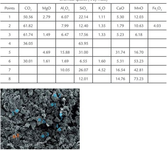
Semi-quantitative chemical analy-sis was performed on the pulverized material. Table 3 systematizes the
com-posite chemical species found and their respective percentages for each point of analysis. Figure 6 shows the
morpho-logical distribution obtained in the slag powder analyses.
Chemical species (% by mass)
Points CO2 MgO Al2O3 SiO2 K2O CaO MnO Fe2O3
1 50.56 2.79 6.07 22.14 1.11 5.30 12.03
2 61.82 7.99 12.40 1.35 1.79 10.63 4.03
3 61.74 1.49 6.47 17.56 1.33 5.23 6.18
4 36.05 63.95
5 4.69 15.88 31.00 31.74 16.70
6 30.01 1.61 1.69 6.55 1.60 5.31 53.23
7 10.05 26.07 4.52 16.54 42.81
8 12.01 14.76 73.23
Table 3 Composite chemical species and their percentage by mass.
Figure 6 Typical morphology found in pulverized slag.
At the analyzed points, the carbon oxide, silicon oxide, calcium oxide and manganese oxide contents presented higher percentages, whereas carbon
oxide presented the highest percentage among all elements. The analysis of the slag showed that point 5 presented the highest values of calcium oxide (31.74 %),
and sum of aluminum and iron oxides (15.88 %), proving that the results found were below the values recommended by AREMA (2001).
Free lime content
In determining the free lime content, the test method prescribed by NBR NM
13/2004 - Portland Cement - Determina-tion of free calcium oxide by ethylene glycol
Figure 7
Percentage graph of free lime content of slag.
The silicon-manganese iron slag presented a total mean of 0.07 % free
lime in a total of 13 trials in 13 weeks. The results show that the percentages
of free lime found in the slag are practi-cally zero.
4. Conclusion
The X-ray diffraction test showed that the sample has a mineralogical com-position of magnetite, quartz, diopside and hematite.
The chemical analysis of silicon-man-ganese iron slag showed that the highest percentage of calcium oxide (CaO) and the sum of the aluminum oxides (Al2O3) and iron (Fe2O3) found were below the values recommended by AREMA (2001), that is, the sample complies with calcium oxide (CaO) limits of less than 45 % and a sum of less than 30 % of aluminum (Al2O3) and
iron (Fe2O3 and FeO) oxides prescribed by the standard.
In the scanning electron microscopy test, the analyzed points that presented, on average, higher percentages were the contents of carbon oxide, silicon oxide, calcium oxide and manganese oxide, with carbon oxide presenting the highest percentage of all the elements. The values found proved that the oxides found were below the maximum values recommended by AREMA (2001).
The free lime content test showed that
silicon-manganese iron slag presented a free lime mean total percentage of approximate-ly zero, proving that the amount of lime in existence is well below the maximum limit recommended by the norm, which attests the inexistence of volumetric expansion.
In the steel production process, silicon-manganese iron slag has, among other things, the content of iron and cal-cium oxides, whose values are acceptable and therefore suitable to be used as railroad ballast, replacing the increasingly scarce and expensive natural materials.
References
ASSOCIAÇÃO BRASILEIRA DE NORMAS TÉCINICAS – ABNT. NBR NM 13: 2004, Cimento Portland - Análise química - Determinação de óxido de cálcio livre pelo etileno glicol. Rio de janeiro, 2004.
ANDRADE, M. L. A., CUNHA, L. M. S., GANDRA, G. T. Panorama da indústria mundial de ferroligas. BNDES Setorial, Rio de Janeiro, n. 10, p. 57-114, set. 1999. ANDRADE, M. L. A., CUNHA, L. M. S. O setor siderúrgico. In: Banco Nacional de
Desenvolvimento Econômico e Social - BNDES. BNDES 50 Anos: histórias setoriais. Rio de Janeiro, 2002. Disponível em: <http://www.bndes.gov.br/conhecimento/livro-setorial/setorial03.pdf.> Acesso em 22 dez. 2009.
AMERICAN RAILWAY ENGINEERING AND MAINTENANCE ASSOCIATION - AREMA. Manual for Railway Engineering. Lanham: American Railway Enginee-ring and Maintenance Association – AREMA, 2001. v. I - IV.
BAGAMPADDE, U., WAHHAB, H. I. A., AIBAN, S. A. Optimization of steel slag aggregates for bituminous mixes in Saudi Arabia. Journal of Materials in Civil Engineering, v. 11, n. 1, p 30 – 35, 1999.
DING, W., OLSEN, S. E. Manganese and silicon distribution between slag and metal in silicomanganese production. In: ISIJ International, v. 40. n.9, p. 850 – 856, 2000.
FERNANDES, G. Comportamento de estruturas de pavimentos ferroviários com utilização de solos inos e/ou resíduos de mineração de ferro associados à geossintéticos. Brasília: Universidade de Brasília, 2005. 253 p. (Tese (Doutorado
em Geotecnia).
391
de ferroviário. Ouro Preto: Universidade Federal de Ouro Preto, 2010. 142 p.
(Dissertação de Mestrado em Geotecnia).
KANDHAL, P. S., HOFFMAN, G. L. Evaluation of steel slag ine aggregate in hot-mix asphalt mixtures. Transportation Research Record, Washington, D.C.,
n. 1583, p. 28 – 36, 1998.
NÓBREGA, L. M. Caracterização mecânica de misturas asfálticas utilizando escó-ria de ferroliga de manganês como agregado. Salvador: Escola Politécnica da
Uni-versidade Federal da Bahia, 2007. 162 p. (Dissertação de Mestrado em Engenharia Ambiental Urbana).
OLSEN, S. E., TANGSTAD, M. Silicomanganese production - process understanding. In: INTERNATIONAL FERROALLOYS CONGRESS INFACON: “TRANS-FORMATION THROUGH TECHNOLOGY”, 10, 2004. Cape Town, South Africa, 2004. p. 231-238. (Produced by: Document Transformation Technologies). ROHDE, L. Escória de aciaria elétrica em camadas granulares de pavimentos. Porto
Alegre: Universidade Federal do Rio Grande do Sul, 2002. 101 p. (Dissertação de Mestrado em Engenharia).
SILVA, E. A. El uso de escoria de acería tratados con emulsiones catiónicas en diversos pavimentaciones. In: CONGRESO IBERO-LATINOAMERICANO DEL ASFALTO, 6, 1991. Cila, Santiago, 1991. p. 18.