*e-mail: [email protected]
1. Introduction
Due to the requirements for energy saving, safety and environment, lightweight of cars/autombile are urgently needed to reduce fuel consumption and emissions. Advanced high strength steels (AHSSs), such as dual phase steel, TRIP (transformation-induced plasticity) steel, TWIP (twinning-induced plasticity) steel, QP (quenching and partitioning) steel, etc., have been studied for many years because they have a good combination of strength and plasticity1-3. Currently, these steels are being intensively developed to meet the requirements of next generation automobile steels which are expected to reduce the costs4.
Fe-Mn alloys, as one kind of AHSSs, have a potential to be the next generation automobile steel on account of they having TWIP/TRIP effect. These alloys have been the focus of recent studies to meet the new requirements imposed by applications, especially in the automotive industry4-6. Li et al.7 reported that the Fe-Mn based alloy exhibited good combination of high tensile strength (over 1 GPa) and large ductility (about 60%). Song et al.8, using strip-casting, obtained Fe-Mn alloy strips with maximum tensile strength 1077MPa and maximum total elongation 25%, respectively. However, the wide utilization of Fe-Mn alloys is limited by several factors. In view of the sharp work hardening behavior9, these alloys are really dificult to be cold rolled in conventional procedures. Moreover, high deformation resistance results in edge cracks during hot rolling; low thermal conductivity makes slab crack in continuously casting process; selective oxidization gives rise to micro scales on the surface10. Hence, new methods or alternative procedures should be taken into consideration to solve or avoid these problems.
Near net shaping technique is regarded as an effective way to solve the problems mentioned above. Atomized powders are frequently employed as raw materials in near-net shape methods because it has an advantage in shaping the complex
components. In addition, the investigation of structure and phase transition of atomized powders is helpful to in exploring the structure formation of spray deposition.
In this work we focused on formed structures and phase transitions in Fe-Mn alloy atomized powders. The inluence of composition and powder size on the structures and phase transition were investigated.
2. Experimental
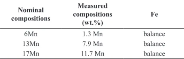
Fe-Mn alloys were prepared from the commercial pure Fe (99.95wt.%) and pure Mn (99.7wt.%). Fe-Mn atomized powders were fabricated by high pressure gas atomization method. Five different powder size ranges, <25μm, 38~53μm, 63~75μm, 106~150μm, >180μm, were screened by using Raymond’s M200 three-D vibrating screen. The atomized powders with three different compositions were prepared. The compositions of the atomized powders were measured by using inductively coupled plasma optical emission spectrometer (ICP-OES). The measured compositions are 1.3, 7.8, and 11.7wt.% Mn, respectively (see Table 1).
The existing phases in the atomized alloy powders were determined by X-ray diffraction (XRD). Micro hardness of the alloy powders were measured by using Vickers hardness tester. Microstructure investigations were carried out by transmission electron microscopy (TEM Rigaku, D/max 2550, JEOL-2010). Specimen for TEM test were prepared using double beam focused ion beam (FIB). Figure 1 shows the preparation process of specimens for TEM by using FIB.
3. Results
3.1. Formed phase of atomized powders
3.1.1. XRD analysis
Figure 2 shows the XRD patterns of the gas atomized powders of Fe-(1.3, 7.9, 11.7) Mn alloys with particle sizes of <25µm, 38-53µm, 63-75µm, 106-150µm, >180µm. It can
Structure and Phase Transition of Fe-Mn Alloy Powders Prepared by Gas Atomization
Yang Yanga, Libing Liua, Yunhu Zhangb, Changjiang Songa*, Qijie Zhaia
aState Key Laboratory of Advanced Special Steels, Shanghai University, Shanghai 200072, China bHelmholtz-Zentrum Dresden-Rossendorf, 01314 Dresden, Germany
Received: August 23, 2014; Revised: October 12, 2015
In this paper we investigated the microstructure and phase transition of atomized Fe-(1.3, 7.9, 11.7 wt.%) Mn alloy powders. The results show that the main phases of Fe-1.3Mn, Fe-7.9Mn and Fe-11.7Mn powders are ferrite, α’-martensite+austenite, α’-martensite+ε-martensite+austenite, respectively. The δ-ferrite in the Fe-1.3Mn powder is the high-temperature δ-ferrite directly formed from liquid, companying by a small number of nanometer sized austenite particles precipitated from the ferrite matrix. In the Fe-11.7Mn powder, the γ-austenite, ε-martensite and α’-martensite are found in the same region and have the K-S orientation relationship, suggesting phase transitions of γ-austenite → ε-martensite → α’-martensite and γ → α’-martensite.
Structure and Phase Transition of Fe-Mn Alloy Powders Prepared by Gas Atomization
2015; 18(Suppl. 1) 11
be seen that the phase structures of the powders vary with the composition: only bcc phase in Fe-1.3Mn powders; bcc and fcc phases in the Fe-7.9Mn powders; bcc, fcc and hcp phases in the Fe-11.7Mn powders. Moreover, the inluence of particle sizes on the phase structure is not found in the Fe-Mn powders with the same composition. According to the literature11-13, the phases with fcc and hcp structures in
Fe-Mn alloys are austenite and ε-martensite, respectively. The bcc phase may be either ferrite or α’- martensite.
3.1.2. Hardness measurement and structures
In order to further determine the formed phases of Fe-Mn atomized powders, microhardness test was conducted due to the existing hardness difference between ferrite and α’-martensite. For the powders with diameter being smaller than 53µm, it is hard to obtain the accurate hardness data due to small size, Figure 3 shows the micro hardness of atomized powders with different size ranges, 63-75µm, 106-150µm, >180µm, respectively.
The micro hardness values of Fe-1.3Mn, 7.9Mn and 11.7Mn powders are in the range of 249.6HV~266.7HV, 403.6HV~478.6HV and 350.4HV~517.1HV, respectively. On account of the fact that the micro hardness value of martensite in Mn-steel is higher than 300HV, it indicates
Table 1. Chemical composition of Fe-Mn alloy powders.
Nominal compositions
Measured compositions
(wt.%)
Fe
6Mn 1.3 Mn balance
13Mn 7.9 Mn balance
17Mn 11.7 Mn balance
that the bcc structure phase is ferrite in the Fe-1.3Mn alloy atomized powders, and should be α’-martensite in both the Fe-7.9Mn and Fe-11.7Mn atomized powders.
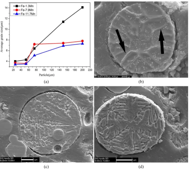
Figure 4a shows the grain sizes of atomized powders. It could be seen that the grain size is proportional to the diameter of powders. Figure 4b-d present SEM images of the cross sections structure of Fe-Mn alloy powders with the diameter of 20µm. The dendrite morphology can be obviously observed in Fe-7.9Mn and Fe-11.7Mn powders. The structure morphology of Fe-1.3Mn powder is not clear but the white particles in nanometer size can be seen in the matrix.
3.2. TEM analysis
Figure 5a-c show the TEM micrographs of Fe-1.3Mn alloy powders with size of 4µm, 75µm and 170µm. A precipitated phase in nano size can be observed in all these three powders (highlighted by red circle and arrows). Figure 5d shows the selected area electron diffraction (SADP) of the precipitated phase, which are identiied as austenite phase.
Figure 6a and 6b show TEM micrographs of Fe-7.9Mn alloy powders under the bright ield and dark ield, respectively. According to the SADP, the phase with a banding shape is austenite in Figure 6a and 6b. Moreover, two sets of lattice coexist, i.e. bcc and fcc structure, as shown in Figure 6c. Figure 6d shows the SADP of matrix which was marked
Figure 2. XRD of Fe-1.3, 7.9, 11.7Mn alloy atomized powders. (a) Fe-1.3Mn; (b) Fe-7.9Mn; (c) Fe-11.7Mn.
Structure and Phase Transition of Fe-Mn Alloy Powders Prepared by Gas Atomization
2015; 18(Suppl. 1) 13
as 1 in Figure 6a. The result presents that the structure of the matrix phase is bcc, which is consistent with the XRD results. The matrix phase should be α’-martensite according to the micro hardness measurement results.
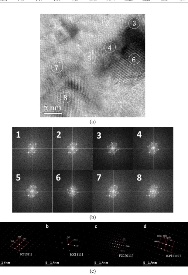
Figure 7 shows a TEM micrograph and SADP of the matrix in the Fe-11.7Mn atomized powder. It can be seen that the matrix phase has a bcc structure, which should be α’-martensite according to the micro hardness measurement results. Figure 8 presents a high resolution transmission electron image and diffraction analysis of a Fe-11.7Mn atomized powder. The image has eight zones (marked with numbers 1 to 8) with different atomic arrangements. The eight zones were characterized by Fast Fourier Transform (FFT). As shown in Figure 8b, there are four different diffraction patterns. Prague ilter was employed to analyze the lattice structure. As shown in Figure 8c, the structure of zone 1 is bcc, with a zone axis of [321]. Zones 2~5 also have bcc structure, with a zone axis of [111]. Zone 6 has fcc structure, with a zone axis of [011]. The structure of zones 7 and 8 is hcp, with a zone axis of [2110]. The high resolution
transmission electron images of Fe-11.7Mn atomized powder show α’-martensite, ε-martensite and γ-austenite all appear in a small region.
3.3. Nano size phase in Fe-1.3Mn powders
Figure 9 are TEM micrographs of the nano precipitated austenite in the Fe-1.3Mn alloy powder. It can be observed that these near spherical nano austenite is in a size range of 10nm ~100nm (see Figure 9a). An ampliied image of a nano precipitated austenite is shown in Figure 9b.
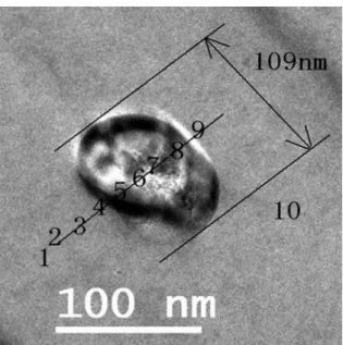
Figure 10a is a TEM micrograph of an elliptical precipitated austenite. The length of its long axis and short axis are 109nm and 72nm, respectively. EDS measurements were performed along a line through the particle as shown in Figure 10. Table 2 shows the corresponding EDS values measured at the 9 points. It can be seen that the precipitated austenite possesses high manganese content. The manganese content continuously increases from the edge to the center of the particle. It means that the precipitated austenite are Mn-rich phase.
Figure 5. The TEM image of cross sections of Fe-1.3Mn alloy powders with size of (a) 4µm, (b) 75µm, (c) 170µm, (d) The SAED pattern of precipitated phases.
Figure 6. TEM micrographs of 5µm Fe-7.9Mn alloy powders (a) bright, (b) dark ield electron image, (c) SADP of austenite, (d) SADP
Structure and Phase Transition of Fe-Mn Alloy Powders Prepared by Gas Atomization
2015; 18(Suppl. 1) 15
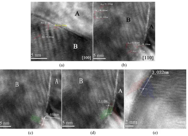
Figure 11 presents HRTEM images of Fe-1.3Mn atomized powder. The Fourier transform and inverse Fourier transform were performed to calculate the angle between the beam spot of zone axis diffraction spots [100] with a value of α=90.25°, the ratio of the distance between the diffraction point with a value of R2/R1=1.006; R3/R1=1.413, and interplanar spacing with a value of D1=D2=2.330Å. The calculated results are almost well matched with the standard Fe-Mn PDF cards, (52-0513: a=b=c=3.66Å,α=β=γ=90°), α=90°, R2/R1=1.000, R3/R1=1.414, D1=D2=1.830Å. The slightly higher interplanar spacing may be due to the lattice distortion and stress. Also, calculation was conducted on Figure 11b, result show that on [110] zone axis direction, α=73°, R2/R1=1.112, R3/R1=1.287; D1=2.640Å; D2=2.500Å. Calculated values are, α=70.53°; R2/R1=1.000; R3/R1=1.155; D1= D2=2.113Å, showing a well match measure.
Figures 11c, 11d and 11e show the mismatch condition between precipitated phase and matrix lattice plane. In the Figure 11c, 8 times identity distance of fcc structure precipitated phase (111) plane (2.448nm) are nearly equal to 5 times of bcc structure matrix ((101)) plane (2.448nm), which means that the mismatch is δ=0.5. As shown in Figure 11d, 10 times identity distance of fcc structure precipitated phase (101) plane (3.112nm) are nearly equal to 5 times of bcc structure matrix (101) plane (3.112nm), which suggests that the mismatch is δ=0.5. In Figure 11e, 11 times identity distance of fcc structure precipitated phase (111) plane (3.032nm) are nearly equal to 8 times of bcc structure matrix (020) plane (3.032nm), which indicates that the mismatch is δ=0.272. According to the mismatch values obtained in the three igures, it presents that the two planes do not parallel each other, showing a non-coherent relationship. According to N-W and K-S relationship14,15, if there is precipitation relationship between austenite and martensite, it will perform coherent or half coherent between (111) fcc and (110) bcc family of crystal planes. However, the non-coherent relationship between
the precipitated phase and matrix in the Fe-1.3Mn atomized powder also means that the matrix and parent phase do not match N-W or K-S relationship. It further conirms that the bcc structure is ferrite rather than martensite.
Moreover, the increase of Mn contents from edge to the center in the precipitated particles (see Figure 10 and Table 2) indicates that there exist the manganese atom diffusion during the formation of precipitated phase, belonging to diffusion phase transition rather than the shear or a simply enrichment of manganese element. Generally, coherent relationship between precipitate phase and matrix is really dificult to be generated during the diffusive transformation on account of the phase transition processes depending on the movement of phase interface. It shows a consistent with the results shown in Figure 11.
From the diffraction lattice in Figure 5d, it can be found that, ferrite (011) plane parallel to austenite (101) plane. Ferrite [100] parallel to austenite [111], have the following relationship,
[ ]
[ ]
bcc 101fcc1 bcc fcc
(011) \( ) 00 \111 (1)
They do not it the the N-W or K-S relationship14,15, which is the relationship that the bcc structure phase precipitated from the fcc structure. Therefore, according to the analysis, it can conclude that the ferrite should be high temperature δ-ferrite and the austenite should precipitated from the high temperature δ-ferrite.
3.4. Orientation relationship of existed phase in
Fe-11.7Mn powders
As mentioned previously, it can be surely concluded that the austenite (nano particles) is precipitated from the ferrite in Fe-1.3Mn powder; the α’-martensite is formed from the austenite in Fe-7.9Mn powder according to the Fe-Mn
Figure 8. 5μm Fe-11.7Mn alloy powder (a) HRTEM, (b) Fast Fourier Transform (FFT), (c) Bragg ilter. Table 2. EDS value of each test point in Figure 9a.
1 2 3 4 5 6 7 8 9 10
Structure and Phase Transition of Fe-Mn Alloy Powders Prepared by Gas Atomization
2015; 18(Suppl. 1) 17
phase diagram. However, the precipitated relationship of the three phases in Fe-11.7Mn powder is still not clear. Hence, the orientation relationships of the phases were analyzed to clarify the precipitated relationship.
As shown in Figure 8a, zones 2~5 are adjacent the zone 6. FFT patterns of zones 2~5 show more than one set of lattice. There are not only bcc lattice on [111] direction but also fcc lattice on [011] direction in this area. In addition, the
two kinds of structures have a K-S relationship. But, [321] direction of zone 1 do not match K-S precipitate relationship. Axis direction of zones 7 and 8 also possess the precipitate relationship, meeting the Bogers-Burgers relationship16,
á' å
111 2110. It indicates that the ε-martensite are transformed from α’-martensite, suggesting that the phase transition of γ → ε-martensite → α’-martensite occurs. Bogers & Burgers17 proposed that α’-martensite formed in intersection region of two imperfect dislocations afcc112
18 and
fcc
a 112
12 . L. bracke
16,
based on this model, found that γ → ε → α’ transformation occurred in Fe-18Mn-0.25C-0.084N alloy.
4. Discussion
As mentioned above, in Fe-1.3Mn alloy powders, ferrite phase should be the high-temperature ferrite formed from liquid. Only some nano sized γ austenite particles precipitate from the ferrite phase because the δ → γ phase transition is largely inhibited due to the high cooling rate. According to Fe-Mn phase diagram, temperature interval of δ-ferrite phase is only about 30 °C in the Fe-7.9Mn alloy. In view of quite high cooling rate of atomized powder, liquid alloy may be directly undercooled to austenite zone. The formed austenite from the melt transforms to α’-martensite at solid state. The room temperature structures are composed of α’-martensite +γ-austenite (retained austenite).
In Fe-11.7Mn powders, room temperature structures include γ-austenite + ε-martensite + α›-martensite. Since it almost is in the austenite zone, the liquid alloy can directly transform into austenite. Subsequently, both γ → ε-martensite → α›-martensite and γ → α›-martensite occurred. Eventually, the room-temperature phases are α›-martensite + ε-martensite + γ-austenite (retained austenite).
Figure 9. 4µm Fe-1.3Mn alloy powder (a) different particle size precipitated phases, (b) 90nm precipitated phase particle.
In Fe-Mn alloys, the phase transition from metastable fcc austenitic to bcc α’-martensite is a most important factor for the strength and plastic increase during plastic deformation. Two-step transformation (γ → ε→ α’) for γ → α’ have been observed. It suggests that ε phase is intermediate phase in the phase transition. As Walter proposed that ε phase can be as the intermediate product or so called “transient phase” formed in γ→α’ transformation18.
5. Conclusions
This paper investigated the solidiication structure of the Fe-(1.3, 7.9, 11.7 wt.%) Mn gas atomized powders. The results show that mainly formed phases are ferrite, α’-martensite + austenite, α’-martensite + ε-martensite + austenite in Fe-1.3, 7.9, and 11.7Mn atomized powders, respectively. In addition, it is found that the formed phases are not evolved with the variation of powder size.
Figure 11. HRTEM micrographs of 95nm precipitated phase in 4µm Fe-1.3Mn powder alloy. Area ‘A’ for matrix phase and area ‘B’ for precipitated phase. “d” is the interplanar spacing value of each lattice plane; (c), (d) and (e) show the mismatch condition between precipitated phase and matrix lattice plane. From high resolution image, left part in (d), which was obtained from (a).
For the Fe-1.3Mn powders, the ferrite phase should be the high-temperature ferrite formed from liquid, and Nano sized austenite particles precipitated from the ferrite matrix. For the 7.9Mn powders, austenite directly formed from liquid alloy due to rapid cooling rate and subsequently transformed to α’-martensite at solid state. But for Fe-11.7Mn powders, both γ → ε-martensite → α’-martensite and γ → α’-martensite occur during the solid-state phase transition.
Acknowledgements
This work was inancially supported by China National Natural Science Foundation (No. 51574162). SEM and XRD were made in the Instrumental Analysis & Research Center at Shanghai University. The authors would like to express sincere thanks for their support.
References
1. Cai ZH, Ding H, Xue X and Xin QB. Microstructural evolution and mechanical properties of hot-rolled 11% manganese TRIP steel. Materials Science and Engineering A. 2013; 560:388-395.
http://dx.doi.org/10.1016/j.msea.2012.09.083.
2. Srivastava AK, Bhattacharjee D, Jha G, Gope N and Singh
SB. Microstructural and mechanical characterization of C– Mn–Al–Si cold-rolled TRIP-aided steel. Materials Science and Engineering A. 2007; 445-446:549-557. http://dx.doi.
Structure and Phase Transition of Fe-Mn Alloy Powders Prepared by Gas Atomization
2015; 18(Suppl. 1) 19
3. Prahl U, Papaefthymiou S, Uthaisangsuk V, Bleck W, Sietsma J and van der Zwaag S. Micromechanics-based modelling of properties and failure of multiphase steels. Computational Materials Science. 2007; 39(1):17-22. http://dx.doi.org/10.1016/j. commatsci.2006.01.023.
4. Aydin H, Jung I-H, Essadiqi E and Yue S. Twinning and tripping in 10% Mn steels. Materials Science and Engineering A. 2014; 591:90-96. http://dx.doi.org/10.1016/j.msea.2013.10.088.
5. Furnémont Q, Kempf M, Jacques PJ, Göken M and Delannay F. On the measurement of the nanohardness of the constitutive phases of TRIP-assisted multiphase steels. Materials Science and Engineering A. 2002; 328(1-2):26-32. http://dx.doi.org/10.1016/ S0921-5093(01)01689-6.
6. Choi CS, Kim JD, Cho TH, Baik SH and Ryu GH. Damping capacities in Fe-X% Mn martensitic alloys. In: Proceedings of the International Conference on Martensitic Transformations; 1992; Monterey. Monterey: Monterey Institute of Advanced Studies; 1992. p. 509-514.
7. Li L, He YL, Zhang M, Fu RY and Shi W. Research and development of advanced automobile sheet steel. Journal of Shanghai University. 2011; 17(4):480-486.
8. Song C, Xia W, Zhang J, Guo Y and Zhai Q. Microstructure and mechanical properties of Fe-Mn based alloys after sub-rapid solidification. Materials & Design. 2013; 51:262-267. http://
dx.doi.org/10.1016/j.matdes.2013.03.094.
9. Huang B, Wang XD, Rong YH, Wang L and Jin L. Mechanical behavior and martensitic transformation of an Fe-Mn-Si-Al-Nb alloy. Materials Science and Engineering A. 2006; 438:306-311.
http://dx.doi.org/10.1016/j.msea.2006.02.150.
10. Song C, Lu W, Xie K, Zhang Y, Xia W, Han K, et al. Microstructure and mechanical properties of sub-rapidly solidified Fe-18wt.%-Mn-C alloy strip. Materials Science and
Engineering A. 2014; 610:145-153. http://dx.doi.org/10.1016/j. msea.2014.05.033.
11. Baik S-H, Kim J-C, Han D-W, Kim T-H, Back J-H and Lee Y-K. Fe-Mn martensitic alloys for control of noise and vibration in engineering applications. Materials Science and Engineering A. 2006; 438-440:1101-1105. http://dx.doi.org/10.1016/j. msea.2006.02.198.
12. Akgün I and Durlu TN. Strength of ε martensite in Fe-23.2% Mn
alloy. Journal of Materials Science Letters. 1994; 13(24):1780-1781. http://dx.doi.org/10.1007/BF00776357.
13. Huang SK, Li N, Wen YH, Teng J, Xu YG and Ding S. Temperature dependence of the damping capacity in Fe-19.35Mn alloy. Journal of Alloys and Compounds. 2008; 455(1-2):225-230.
http://dx.doi.org/10.1016/j.jallcom.2007.01.147.
14. Kurdjumov G and Sachs G. Over the mechanisms of steel
hardening. Zeitschrift fur Physik. 1930; 64:325-343.
15. Nishiyama Z. X-ray investigation of the mechanism of the transformation from face-centered cubic lattice to body-centered cubic. Science Reports of the Tohoku Imperial University. 1934; 23:637-664.
16. Bracke L, Kestens L and Penning J. Transformation mechanism
of α′-martensite in an austenitic Fe-Mn-C-N alloy. Scripta Materialia. 2007; 57(5):385-388. http://dx.doi.org/10.1016/j. scriptamat.2007.05.003.
17. Bogers A and Burgers W. Partial dislocations on the {110} planes in the BCC lattice and the transition of the FCC into the BCC lattice. Acta Metallurgica. 1964; 12(2):255-261. http:// dx.doi.org/10.1016/0001-6160(64)90194-4.


![Figure 11 presents HRTEM images of Fe-1.3Mn atomized powder. The Fourier transform and inverse Fourier transform were performed to calculate the angle between the beam spot of zone axis diffraction spots [100] with a value of α=90.25°, the ratio of the](https://thumb-eu.123doks.com/thumbv2/123dok_br/18881434.422752/6.765.62.718.98.426/presents-atomized-fourier-transform-transform-performed-calculate-diffraction.webp)