Sensitizing The Mode Shapes Of Beam Towards
Damage Detection Using Curvature And Wavelet
Transform
N. G. Jaiswal, D. W. PandeAbstract: The paper presents the numerical studies for damage detection in beam structure with mode shape curvatures and its spatial wavelet transform. A small simulated perturbation in the form of transverse slots to be treated as damage in beams and a three stage damage detection process for amplifying the discontinuityis proposed here. Vibration data obtained from the perturbed system is processed for mode shapes which are converted into mode shape curvatures and subsequently fed to the wavelet transform. The study revealsthat the proposed transformation is better in sensitizing damage-induced features than the classical approach based alone on bare modal data. It is observed that the decomposition of the spatial signal into wavelet details can identify the damage position in beam like structure by showing relatively larger peaks at the position of the damage.
Index Terms: Curvature; Damage detection; Mode Shape; Wavelet Transform
————————————————————
1.
I
NTRODUCTIONVarious techniques for structural damage detection involving modal parameters have widely been used over the past few decades. As such, the modal parameters of a structure are easy to obtain from forced, free or ambient vibration measurements. In many of these techniques, mode shapes or the data derived from mode shapes have been used for location-detection of damage. From damage sensitivity perspective,the data obtained from the mode shape in curvature form seemsfar promising than the one from mode shapes. In this paper, the mode shape curvatures from damaged modes are analyzed with wavelet transform, a powerful tool, in a bid to increase its sensitivity towards damage. The characteristic modal data of free-free beams are obtained from finite element modal analysis. This data is studied at three stages i.e. mode shapes; its curvature and subsequent wavelet transform to increase the sensitivity. The synergetic effect helps to visualize the relatively larger peaks at damaged location. The damaged location which otherwise are not much prominent in mode shapes and its curvatures, are clearly and more conspicuously seen in detail part of the wavelet transform. Various approaches have been proposed in the literature for damage detection and localization.Pandey et al. [1] proposed the fundamental mode shape curvature to be a sensitive parameter for damage localization.Curvature was calculated and utilized for damage localization of a simulated beam discretized into a number of finite elements. Douka et al. [2] investigated experimental and analytical identification ofcrack in cantilever beam depending on wavelet analysis. The size and the location of the crack is determined using wavelet transform for fundamental mode of vibration. Due to the rapid changes in the spatial difference of the response, the crack location is determined. Wang[3] have reported an investigation for different crack depths detection of a cantilever beam under a static displacement with the spatial wavelet transform.
Gabor wavelet used to analyze and identify the static profile of cantilever beam with the crack subjected to static displacement. The spatial wavelet transform approved the effectiveness to identify the damagein the beam.Kisa et al. [4]analyzed the free vibration for uniform and step cracked beams with circular cross section and presented a novel numerical technique. Thus the knowledge of model data of cracked beams has formed an important aspect in assessing the structural failure. In additions, it is found that locations and sizes of crack can notably influence the model features.Çam et al.[5] have investigated the dynamic analysis depending on the impact shock method of beam with crack. The effect of location and the depth of crack investigation have been done experimentally. The study aimed to collect the information of different depth and different location of crack in cracked beam by vibration analysis. The experimental results evaluated with finite element model constructed by ANSYS software.Zheng et al. [6] obtained the natural frequencies and mode shapes of a cracked beam with rectangular cross sectional by using the finite element method. For a cracked beam, a new shape interpolation function has been developed to compute the vibration modes.Patil and Maiti [7] have utilized a method for prediction of location and size of multiple cracks based on measurement of natural frequencies for slender cantilever beams. Nikolakopoulos et al. [8] proposed a method to detect the location and the depth of crack in the structure. Eigen frequency measurements are used to identify the location and depth of crack in an examined frame structure. It has been approved that there is a significant effect of crack parameters on the dynamic behavior of the beam. This influence is mainly based on the location and the size of crack. The method depends on the measurements of the first two or three eigenfrequencies of the structure. The location and the depth of cracks can be estimated by plotted contours.Baghiee et al.[9] presented methods to detect the damage and location in structure. It is emphasized that the modal curvature method is the foundation for non-destructive damage finding for many dynamic methods. A modal curvature is more sensitive to detect the location of damage compared with modal displacement. Hence, from the second derivative of modal displacement it is possible to detect the location of damage. Salawu et al. [10] have applied the central difference approximation. Direct changes in mode shape at each point are studied. The authors discussed the proper selection of ______________________
N. G. Jaiswal: Department of Mechanical Engineering,
PVG’s College of Engg & Technology, Pune (India)
D. W. Pande: Department of Mechanical Engineering,
267 mode. The response is to be measured at a sufficient number
of points for large structures.Ratcliffe [11] proposed a frequency and curvature based experimental method for locating damage in structures. The method uses measured frequency response functions to obtain displacement as a function of frequency. The displacement functions are converted to curvature functions which are further processed to yield a damage index. Experimental modal curvature difference between damaged and undamaged beam is studied only for the fundamental mode.Yam et al. [12] discussed the sensitivity of static and dynamic parameters to damage occurring in plate-like structures. Damage is
quantified in the form of damage indices, defined as the
relative changes of the corresponding parameters between the intact and damaged cases. Damage is simulated by reducing the thickness of the plate at element. It is concluded that, as far as the sensitivity to damage is concerned, the deflection curvature is the most informative parameter among the static parameters, and the curvature mode shape among dynamic parameters.Owolabi [13]proposed the damage detection scheme which is based on the measured changes in the first three natural frequencies and the corresponding amplitudes of the measured acceleration frequency response functions. Experiments were carried on aluminum beams with
fixed ends and simply supported with varying magnitude of
damage. Jeong-Tae Kim [14] reported the frequencybased and mode shape based damage detection algorithms. He presented the methodology to locate and estimate the size of damage in structures for which two frequencies and/or mode shapes are available. These parameters are generated from
finite element models or several numerically simulated
damage scenarios. Maia [15] performed numerical simulations on a simple beam in order to compare various damage detection methods based on mode shape changes. It was found that the methods based on the curvatures performed better over FRF based methods.Sampaio et al. [16] used the FE model of a free–free beam. Relative
Damage Quantification Indicator is proposed based on number of extracted natural frequencies. The method presented in this paper belongs to the class of methods that use the change in the operational deflection shapes (ODSs) to detect, locate and relatively quantify the damage.Maosen Cao et al. [17] studied the relation between fundamental
mode shape and static deflection. Thus the sensitivity of these features to damage in cantilever beams is comprehensively investigated. FEM analysis is done to establish a sensitivity rule regarding the use of these features in damage detection exercise in cantilever beams. Koushik, and Samit Ray [18] studied the cantilever shear beam, discretized into a large number of elements. It is demonstrated that the change in the fundamental mode shape due to any damage is an excellent indicator of damage localization as it is found to be discontinuous at the location of damage. Further, the change in higher derivatives (i.e., slope and curvature) of the fundamental mode shape is shown to be sensitive enough in damage localization.
2.
F
UNDAMENTALS OFS
PATIALW
AVELETT
RANSFORMThis section presents a brief background on wavelet analysis utilized in this paper. Mostly wavelets are used to analyze signals of time domain. Using a selected mother wavelet
function�(�), the continuous wavelet transform of a signal �(�)is defined as equation (1)
�� , = 1 � � �−∞+∞ �− �� (1)
where and are dilation and translation parameters respectively. The bar over � � indicates its complex conjugates. Equation (2) gives the signal reconstruction by an inverse wavelet transform.
�� , � �− 12� � (2)
A wavelet family associated with the mother wavelet �(�) is generated by dilation and translation. The translation parameter , indicates the location of the moving wavelet window in the wavelet transform. Shifting the wavelet window along the time axis implies examining the signal in the neighborhood of the present window location. Therefore, information in the time domain still remains, in contrast to the Fourier transform, where the time domain information becomes almost invisible after the integration over the entire time domain. The dilation parameter ,indicates the width of the wavelet window. A smaller value of implies a higher resolution filter, i.e., the signal is examined through a narrower wavelet window over a smaller scale. In practical signal processing, a discrete version of wavelet transform (equation 3 to 7) is often employed withdiscretized dilation parameter and the translation parameter . In general, the procedure becomes much more efficient if dyadic values of
and are used, i.e.
= 2 ; = 2 , ∈ (3)
where =set of positive integers.
In the discrete wavelet analysis, a signal can be represented by its approximations and details. The detail at level is defined as
= ∈ , �, (�) (4)
and the approximation at level is defined as
� = > (5)
It implies
�−1 =� + (6)
and
� � =� + ≤ (7)
clearly seen in the original data or the results from other methods. For the wavelet analysis of signals of spatial domain, one may simply replace time with a spatial coordinate by considering a spatial signal� � . In this work, discrete wavelet transform (DWT) is used to analyze the spatial signal i.e. mode shape and mode shape curvature of the beam. DWT plays a role of dyadic filter. The spatial DWT analyzes the signal by implementing a wavelet filter of particular spatial frequency band to shift along a length of beam axis. The local examination of the spatial signal is possible by considering various levels of decomposition. A graphical representation of DWT of a signal is shown in Fig. 1. The spatial signal may be decomposed into a tree structure with wavelet details and wavelet approximations at various levels as follows.
Fig. 1: Three level discrete wavelet transform decomposition
3.
N
UMERICALS
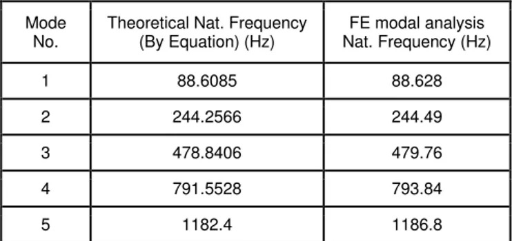
TUDYA finite element (FE) model of a free-free boundary condition beam of dimensions 0.6 m (length) x 0.06 m (width) x 0.006 m (thickness) is created and subsequently discretized with beam elements. The model is subjected to number of damage scenarios and analyzed. To validate the finite element model, the first five natural frequencies obtained from the FE model are compared with the natural frequencies obtained from theoretical equations (refer Table No.1). Equation (8) gives theoretical natural frequencies of beam with free-free boundary condition. � = � � 2 × ×�×
2× � (8)
Where
is modulus of elasticity (2.1 × 10¹¹�/ 2) is moment of inertia
ρ is density of material (7850kg/m3)
� is cross section area of beam � is length of beam (0.6 m)
is ranging from 1 to 5 for first five modes �1= 4.73, �2 = 7.832, �3 = 10.995,
�4= 14.137, �5 = 20.420
Table 1: Comparison of Natural Frequencies obtained by theoretical equations and by FE analysis
Mode No.
Theoretical Nat. Frequency (By Equation) (Hz)
FE modal analysis Nat. Frequency (Hz)
1 88.6085 88.628
2 244.2566 244.49
3 478.8406 479.76
4 791.5528 793.84
5 1182.4 1186.8
3.1 Damage Scenarios
The damage is introduced as a transverse rectangular cut of very small size 1mm (depth) x 0.5mm (wide) at a distance of 0.1 m from one end. Modal analysis is carried out and the model is solved for the first five natural frequencies. The mass normalized mode shapes corresponding to the first five natural frequencies are obtained for the damaged conditions. The nodal displacement data for the transverse vibrations are analyzed. For each mode, modal curvatures are obtained. Central difference approximation is used to estimate mode shape curvatures from the mass normalized mode shapes obtained from the finite element analysis. Numerically, it is calculated as
� , =
� +1 ,−2 �, +� −1 ,
ℎ2 (9)
where �, represents modal curvature, first subscript represents node number, second subscript represents the corresponding mode number, ℎ represents element length as the beam is discretized with elements of equal length and �, represents the mass normalized modal value for the �ℎnode in the �ℎ mode. Reduction in the stiffness because of damage results in an increase of the local modal curvature.
3.2 Wavelet Analysis of Mode shape and Mode Shape Curvature
Utility of the wavelet analysis is observed when the damaged mode shapes and the curvatures are fed to the wavelet transformation. Mode shape and mode shape curvature for damaged modes are treated here as signals for wavelet analysis (spatial domain). The wavelet transform is carried out in Matlab using the wavelet toolbox. The Debauchies (db4) mother wavelet is used in this analysis. It has the characteristics which make the visualization of the signal discontinuities clear. Three-level wavelet decomposition is performed on the signal to obtain approximate and detail
information, so that the signal characteristics that are not apparent in the original signal can be revealed in details. Approximate part reflects main features of the signal. Detail part reflects faster fluctuations of the signal. The results are plotted in Fig. 2 to 11.
4.
D
ISCUSSIONS ONG
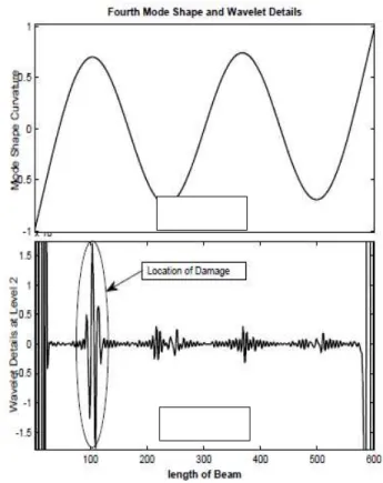
RAPHSMode shapes and mode shape curvatures are obtained for damaged free–free beam when the damage is in the form small transverse rectangular cut of size 1mm (depth) and 0.5 mm (wide). This spatial data is treated as signal for wavelet analysis. Mode shapes and their wavelet details are shown for first five modes when the damage is placed at a distance of 0.1 m from one end (refer Fig. 2, 4, 6, 8, and 10). Visual inspection of these figures (Fig. 2a, 4a, 6a, 8a and 10a) does not reveal any discontinuity for this small level of damage. But detail part of wavelet transformation of these mode shapes shows relatively larger peaks at the damage location. At the ends of the beam the wavelet data obtained may not be reliable as unexpected peaks are observed at the ends. The effort is needed to pinpoint this problem in numerical analysis in future studies. As expected, the sensitivity of the same level of damage at same location is enhanced when mode shape curvature is obtained. Fig. 3, 5, 7, 9, 11 show mode shape curvature and its wavelet detail for first five modes. The peaks observed at the damaged location in wavelet details of
Si
gn
al
A1
A2A3
A3
D4
D3
269 mode shape curvatures (Fig. 3b, 5b, 7b, 9b, 11b) are more
prominent than the peaks observed in wavelet details of mode shapes. Higher modes are much informative as far as detection of the damage is concerned as the prominence of peaks is more conspicuous towards higher modes. Moreover, at the ends of beam, not any unexpected peaks are observed in detail part (unlike wavelet details of mode shape).
Fig.2: 1st Mode Shape (2a) and its Wavelet Transformation – detail part (2b)
Fig.3: 1st Mode Shape Curvature (3a) and its Wavelet Transformation-detail part (3b)
Fig.4: 2ndMode Shape (4a) and its Wavelet Transformation -detail part (4b)
Fig.5: 2ndMode ShapeCurvature (5a) and its Wavelet Transformation-detail part (5b)
Fig. 2a
Fig. 3b
Fig. 3a
Fig. 5b Fig. 5a Fig. 4a
Fig. 4b
Fig. 6: 3rdMode Shape (6a) and its Wavelet Transformation -detail part (6b)
Fig.7: 3rdMode ShapeCurvature (7a) and its Wavelet Transformation -detail part (7b)
Fig.8: 4thMode Shape (8a) and its Wavelet Transformation -detail part (8b)
Fig.9: 4thMode ShapeCurvature (9a) and its Wavelet Transformation -detail part (9b)
Fig. 6b Fig. 6a
Fig. 7a
Fig. 7b
Fig. 8a
Fig. 8b
Fig. 9a
271
Fig.11: 5thMode ShapeCurvature (11a) and its Wavelet Transformation -detail part (11b)
5.
C
ONCLUSIONTwo sensitive parameters i.e. mode shape curvature and Wavelet transform, in the study of damage detection exercises are simultaneously employed on damaged mode shapes. The combination is proved to be more sensitive while
detecting small level of damages in structures. The quantification of severity of damage can further be explored based on wavelet details of damaged mode shapes and curvatures.
A
CKNOWLEDGEMENTThe authorsacknowledge B.C.U.D.,SavitribaiPhule Pune University for supporting to this work.
R
EFERENCES[1] Pandey A. K., M. Biswas, and M. M. Samman. "Damage detection from changes in curvature mode shapes." Journal of sound and vibration 145.2 (1991): 321-332.
[2] Douka E., S. Loutridis, and A. Trochidis. "Crack identification in beams using wavelet analysis." International Journal of Solids and Structures 40.13 (2003): 3557-3569.
[3] Wu N., and Q. Wang. "Experimental studies on damage detection of beam structures with wavelet transform." International Journal of Engineering Science 49.3 (2011): 253-261.
[4] Kisa, Murat, and M. ArifGurel. "Free vibration analysis of uniform and stepped cracked beams with circular cross sections." International journal of engineering science 45.2 (2007): 364-380.
[5] Çam, Ertuğrul, SadettinOrhan, and Murat Lüy. "An
analysis of cracked beam structure using impact echo method."NDT & E International 38.5 (2005): 368-373.
[6] Zheng, D. Y., and N. J. Kessissoglou. "Free vibration analysis of a cracked beam by finite element method." Journal of Sound and Vibration 273.3 (2004): 457-475.
[7] Patil, D. P., and S. K. Maiti. "Experimental verification of a method of detection of multiple cracks in beams based on frequency measurements."Journal of Sound and Vibration 281.1 (2005): 439-451.
[8] Nikolakopoulos, P. G., D. E. Katsareas, and C. A. Papadopoulos. "Crack identification in frame structures." Computers & structures 64.1 (1997): 389-406.
[9] Baghiee, Neda, M. Reza Esfahani, and Kazem Moslem. "Studies on damage and FRP strengthening of reinforced concrete beams by vibration monitoring."Engineering Structures 31.4 (2009): 875-893.
[10] Salawu, Olusegun S., and Clive Williams. "Bridge assessment using forced-vibration testing."Journal of structural engineering 121.2 (1995): 161-173.
[11] Ratcliffe, Colin P. "A frequency and curvature based experimental method for locating damage in
Fig. 10a
Fig. 10b
Fig. 11a
structures." Journal of vibration and acoustics 122.3 (2000): 324-329.
[12] Yam, L. H., Y. Y. Li, and W. O. Wong. "Sensitivity studies of parameters for damage detection of plate-like structures using static and dynamic approaches." Engineering structures 24.11 (2002): 1465-1475.
[13] Owolabi, G. M., A. S. J. Swamidas, and R. Seshadri. "Crack detection in beams using changes in frequencies and amplitudes of frequency response functions." Journal of sound and vibration 265.1 (2003): 1-22.
[14] Kim, Jeong-Tae, et al. "Damage identification in beam-type structures: frequency-based method Vs mode-shape-based method." Engineering structures 25.1 (2003): 57-67.
[15] Maia, N. M. M., et al. "Damage detection in structures: from mode shape to frequency response function methods." Mechanical systems and signal processing 17.3 (2003): 489-498.
[16] Sampaio, R. P. C., and N. M. M. Maia. "Strategies for an efficient indicator of structural damage."Mechanical Systems and Signal Processing 23.6 (2009): 1855-1869.
[17]Cao, Maosen, et al. "Sensitivity of fundamental mode shape and static deflection for damage identification in cantilever beams." Mechanical Systems and Signal Processing 25.2 (2011): 630-643.