Article
Printed in Brazil - ©2015 Sociedade Brasileira de Química0103 - 5053 $6.00+0.00A
*e-mail: [email protected]
Electrosynthesis and Characterisation of Polymer Nanowires from Thiophene and
its Oligomers
María Angelica del Valle,*,a Andrea C. Ramos,a Fernando R. Diaza and Manuel A. Gacituab
aLaboratorio de Electroquímica de Polímeros (LEP), Departamento de Química Inorgánica,
Facultad de Química, Pontificia Universidad Católica de Chile, Av. V. Mackenna 4860, 7820436 Macul, Santiago, Chile
bLaboratorio de Bioingenieria, Facultad de Ingenieria y Ciencias, Center of Applied Ecology and
Sustainability (CAPES), Universidad Adolfo Ibañez, Av. Diagonal Las Torres 2640, 7941169 Santiago, Chile
Validating methodology formerly reported, polythiophene electrosynthesised as nanowires from the monomer and some of its oligomers is now described. The work is conducted on a platinum electrode previously modified with a template that tunes the polymer growth inside the confined space of the pores. In addition, it was confirmed that the use of larger chain-length oligomers as starting unit helps to obtain more homogeneous wires, although its adhesion to the supporting substrate works against. Characterisation allows to verify the morphology and to confirm higher levels of doping/undoping of the nanostructures as compared to the corresponding bulky deposits, which points to improved macroscopic properties. It is demonstrated that this strategy allows obtaining nanowires of very small diameter, ranging from 2.8 to 4.0 nm; thus demonstrating that the use of this approach enables the direct obtainment of nanowires upon the electrode surface, with the obvious advantage that this implies.
Keywords: electropolymerisation, polythiophene nanowire, thiophene oligomers, template
Introduction
Nanostructured materials have received great attention due to, among other properties, their high surface area, new size effects and significantly improved kinetics.1 Much attention has been paid to nanostructured conducting polymers (CP) because of their enhanced performance in technological applications, as compared with the corresponding bulk polymer,2,3 as well as to their potential applications in energy storage, sensors, photovoltaic cells, etc.4-6 Furthermore, polythiophene CP, with its unique optical and electrical properties and high environmental stability, has recently been extensively studied; this has led to many developments intended for applications such as electrochromic devices, solar cells, batteries, etc.7-10
A variety of methods have been used for the synthesis of nanostructures, among them stand out the templated pathway, use of a “hard-template” or “soft-template” to physically guide nanometric growth and those that do not consider the use of a template (“template-free”).6,11,12 In the
current work a mixed methodology is reported, in which only electrochemical techniques are used to obtain the polymeric nanostructures.13,14 Most remarkable advantages of both methods, soft- and hard-template, are employed at different stages of the synthesis. First of all, the renowned silicon-oxide porous films are prepared on the electrode using the soft-template surfactant approach. Then, this inert nanostructured oxide surface will act as hard template in the CP electrosynthesis. The advantage of this mixed approach is the ability to control the morphology of the polymeric deposit since the electrode surface is previously modified by a silica mesoporous film.15 Pores on the oxide film are known to be perpendicular to the electrode surface, hence, the nanowires may grow directly in this confined space and consequently, post-treatment stages are unnecessary. Other advantages may be mentioned such as its low cost, reproducibility and versatility (can be used on various electrodic substrates and for any type of electrodeposit).
solubility,18 temperature19 and starting unit chain-length.20 From these studies a previously reported model was inferred,17 which has been corroborated and continuously validated by studying different CPs, e.g., polythiophene and its derivatives, polyaniline, polypyrrole and polyfuran; this model has been considered one of the most realistic models proposed thus far.21-24
Consequently, regarding the advantages of nanostructured CPs, the capability of controlling and improving the morphology of the polymeric deposits determines the efficiency of the different devices where they may be further applied.25 On this regard, there are several reports mentioning that, when applying
π-conjugated materials on different devices, a key-aspect
to be considered is the surface homogeneity and orientation. Electronics design (light emitting diodes, field transistors, photovoltaics, etc.) requires materials with oriented structure (for appropriate charge movement and dissipation); hence, nanostructured electronics is a promising research field with proven success.26-28
Electrochemical synthesis tools and the knowledge of an electropolymerisation model enable full control of the electrodeposit based on experimental variables and starting unit. Therefore, in this report polythiophene nanowires electrosynthesis is described using the monomer and oligomeric species as starting unit; growth takes place inside confined space to yield the nanostructures. From previous reports,20 it has been proven that the use of oligomers instead of monomer for electrochemical deposition of polythiophene yields more homogeneous film surfaces. Moreover, when employing oligomers, as the starting unit chain length increases, the film evenness is enhanced. In addition, the control exerted by the template enables nanostructured electrodes preparation possessing enhanced features, suitable for use in various types of devices.
Experimental
For the electrochemical studies, a CH Instruments potentiostat coupled to a computer with appropriate software to control experimental conditions and data acquisition was utilised. A three-compartment anchor-type electrochemical cell was used. A 0.03 cm2 geometric area Pt disc was the working electrode while a platinum wire coil of large area was the counter electrode. The reference electrode was a Ag|AgCl electrode immersed in a tetramethylammonium chloride solution, whose concentration is adjusted so the potential matches that of a saturated calomel electrode (SCE) at room temperature.29
T h e r e a g e n t s u s e d a s s t a r t i n g u n i t s w e r e , thiophene (Th, 99% m/m), 2,2’-bithiophene (BTh,
97% m/m), 2,2’:5’,2”-terthiophene (TTh, 99% m/m), 2,2’:5’,2’:5’,2’’’-quaterthiophene (QTh, 96% m/m), acetonitrile solvent (99.9%). Tetrabutylammonium hexafluorophosphate (TBAPF6) was the supporting electrolyte (99% m/m). All reagents were purchased from Aldrich and used as received.
Platinum electrodes modified with a porous silica film (Pt|(SiO2)n) were prepared using the approach proposed by Walcarius et al.,15 which has already been used with success in works reported elsewhere.3,13,14 Template synthesis is highly reproducible, always obtaining the same pore size. Permeability and area of the electrode were evaluated by analysing the cyclic voltammograms (working window 0.3 and 0.8 V vs. SCE) in an acetonitrile solution containing 1.24 mmol L-1 ferrocene (98%, Aldrich) and 0.1 mol L-1 TBAPF
6 (scan rate: 50 mV s-1). Thus, the use of the ferrocene/ferrocenium couple allowed, using the Randles-Sevcik equation,30 determining the electrode area and current density reported herein.
Assays for removing the template were performed using a 50:50 (v/v) HF (extra pure, Aldrich) and double distilled water mixture. Nanolayers were characterised measuring their voltammetric response (scan rate: 10 mV s-1) in a solution containing just supporting electrolyte and comparing the result with deposits obtained under the same experimental conditions but without template.
Transmission electron microscopy (TEM) images of the dispersed polymer deposits onto a copper mesh were obtained on a LEO electron microscope, model 142VP. Samples for TEM measurements were prepared by mechanically removing (scraping) some pieces of the deposit, grinding them firstly on a mortar, and then directly supported on the copper mesh.
Results and Discussion
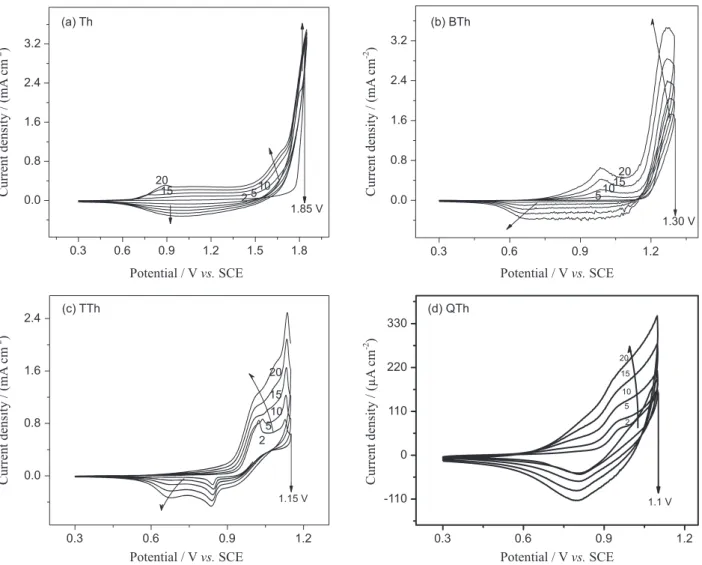
First, the conditions for the electropolymerisation on Pt of the different starting units [(thiophene (Th); 2,2'-bithiophene (BTh); 2,2':5',2"-terthiophene (TTh), and 2,2':5',2":5",2"'-quaterthiophene (QTh)] were optimised, by setting the parameters (concentration of the starting unit, potential scan rate, number of successive voltammetric cycles, potential window and supporting electrolyte concentration) that allowed highly reproducible recording profiles as those shown in Figure 1.
all cases the formation of a deposit that changes from dark to light brown or orange was checked out, when scanning from the more positive potential to the initial one (doped and undoped forms, respectively), in agreement with previous reports. In addition, this could be interpreted as evidence that all the starting units give rise to an analogous polymer.31,32
Another important aspect to underline when oligomers are used is the remarkable decrease in oxidation potential (highlighted in Figure 1) as the starting unit chain length increases. This fact is explained by the greater conjugation of the radical generated by the oxidation: increased stability favours its formation.16,20 By introduction of oligomer species and precise control of experimental variables, polythiophene overoxidation can be prevented. It is known that polythiophene may be obtained by applying and oxidative perturbation of ca. 2.00 V vs. SCE to thiophene-containing anhydrous conditions. However, polythiophene films present an intrinsic oxidation (p-doping) potential
near 1.00 V vs. SCE. These two features are known as the polythiophene paradox phenomenon, since when polymerising from the monomer the film suffers overoxidation at the same time, impairing its conductivity properties. Selecting oligomers instead of monomer for deposition, since they require lower potential values, may prevent such phenomenon.33
Particularly, pQTh deposits were very thin, probably due to the low solubility of the starting unit into the working solution that makes necessary the use of very dilute solutions (QTh concentration was 0.4 mmol L-1). Moreover, it is observed that the adhesion of the polymer to the electrode is strongly affected by the potential sweep rate and the size of oligomer fragments. Consequently, it was established that scanning at 5 mV s-1 complete and homogeneous modification of the electrode surface was achieved from these starting units.34 As a consequence, the polymer deposit was achieved when applying four times more cycles.
0.3 0.6 0.9 1.2 1.5 1.8
0.0 0.8 1.6 2.4 3.2
Current density / (mA
cm
)
-2
Current density / (mA
cm
)
-2
Current density / (µA
cm
)
-2
Current density / (mA
cm
)
-2
1.85 V (a) Th
20
2 5 10 15
0.3 0.6 0.9 1.2
0.0 0.8 1.6 2.4 3.2
(b) BTh
1.30 V 510
1520
0.3 0.6 0.9 1.2
0.0 0.8 1.6
2.4 (c) TTh
Potential / Vvs.SCE Potential / Vvs.SCE
Potential / Vvs.SCE Potential / Vvs.SCE
1.15 V
2 5
10 15 20
0.3 0.6 0.9 1.2
-110 0 110 220 330
(d) QTh
20 15 10 5 2
1.1 V
Figure 1. Voltammetric profile of 10 mmol L-1 Th, 5.1 mmol L-1 BTh, 3.42 mmol L-1 TTh and 0.4 mmol L-1 QTh, in 0.1 mol L-1 TBAPF
6 and anhydrous
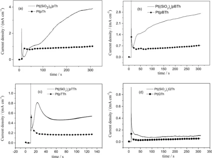
Once the appropriate potentiodynamic range was established, the optimal potential for the potentiostatic electropolymerisation was determined. Figure 2 exhibits transients recorded using this potentiostatic method in response to the formation of a conductive film. The current density of these results was determined by dividing the output current with the area resulting from the calculation using the Randles-Sevcik equation.35 This requires the study of the electrochemical response of Pt and Pt|(SiO2)n in a solution containing the ferrocene/ferrocinium redox couple. This way, Pt and Pt|(SiO2)n surfaces presented a surface of 0.038 and 0.012 cm2, respectively, i.e., ca. 69% of the Pt surface was covered with silica deposit and the remaining 31% represents the pore area.
It is reasonable that when starting units such as BTh and TTh are used, shorter time (compared with that obtained for Th) would be required to initiate the nucleation and growth process, because the oxidation of such species will afford tetramers and hexamers that will result in a swifter interface saturation, and hence precipitation on the electrode. This result is consistent, first, with the findings reported by
Xu et al.,36,37 namely that the electrochemical formation
of polythiophene commences from 6-ring oligomers; and second, with the number of references that demonstrated the solubility is what determines the nucleation starting time.16-22 The induction time for polythiophene electrodeposition from QTh, however, is much longer, which may appear inconsistent with the above, but in this case the interpretation must consider that TTh oxidation immediately yields oligomers with 8 monomer units that, by their large size and linear form, present little ability of adhesion to the surface, hindering thus the nucleation on the electrode. This is in agreement with the fact that, even though the chain length increase promotes conditions for obtaining a more homogenous deposit, as the starting unit chain length increases detachment of the polymeric material is observed and coating of the electrode becomes more difficult consequently. Such trend would be limited by the adhesion of the respective nuclei onto the electrode.
A most interesting fact is that for each starting unit current outputs were always higher when using the Pt|(SiO2)n electrode. Previous studies on potentiodynamic synthesis
Figure 2. Current density/time transient recorded during polythiophene electropolymerisation from Th (10 mmol L-1), BTh (5.1 mmol L-1), TTh
of polythiophene proved that higher current outputs were observed when employing such silica-modified surface.3 It was argued that the presence of the pores hindered early-synthesised oligomer radicals movement towards the bulk solution; hence, current output is enhanced (or catalysed) by reactive species trapped within the pores. Also, this phenomenon is explained by the fact that an enhanced electroactive surface is formed (known also to cause current loop during potentiodynamic polymerisation) a feature that is boosted if nanowires are formed.
Polymer deposits on Pt|(SiO2)n coated electrodes were potentiostatically obtained at different times, because, as noted, no experimental parameters exist to elucidate in situ the optimum electrosynthesis time to take up the template pores without overfilling them. To this purpose, the voltammetric response of electrodeposits prepared under identical conditions upon the bare and template-coated electrode, in solutions of supporting electrolyte, was studied. Thus, in the early stages the i-t transient found for polymers grown on Pt|(SiO2)n and on Pt showed a noticeable difference; this is due to the formation of structures with
different nucleation and growth mechanisms (NGM). Considering that the presence of porous silica template exerts control by shaping the polymer growth into the confined space of the pores and from i-t current profile, it can be postulated that it corresponds to an exponential current increase due to one-dimensional (1D, along the template pore) increase, which will be confirmed later on by determining the respective NGM.
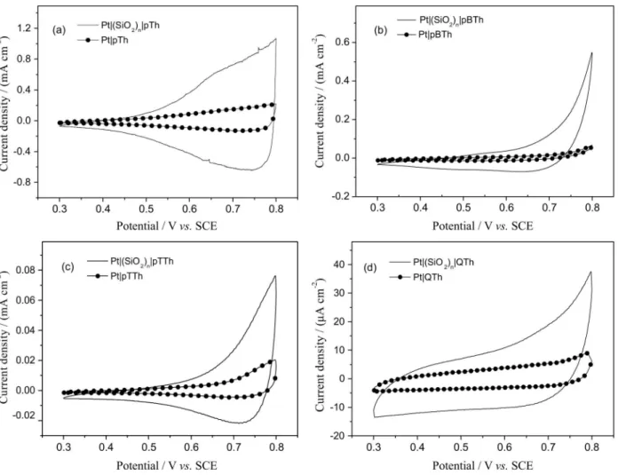
Figure 3 depicts voltammetric responses of deposits in a solution containing just supporting electrolyte. It is possible to verify that the polymer obtained on Pt|(SiO2)n exhibits a current density much higher than that of the bulk polymer. This increase would indicate a greater effective area due to nanowires formation when the polymer grows into the template confined spaces.6 The significant charge increase of the p-doping/undoping processes, precisely the result of a greater surface area of the electrode modified with polythiophene nanowires is evidence that nanostructured polymers from Th, BTh, TTh and QTh were obtained. By comparing the higher current outputs of the wires with the one of the massive film it can be stated that conductivity
Figure 3. Response in 0.1 mol L-1 TBAPF
6, CH3CN of polythiophenes electrosynthesised, respectively, from Th, BTh, TTh, and QTh under the conditions
(even if not calculated) of the nano-structured polymer was effectively enhanced.
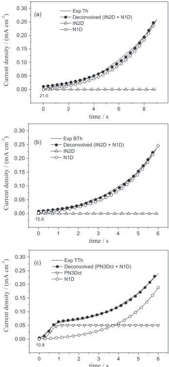
However, it is important to complement the electrochemical characterisation by determining the respective NGM. The diffusion current, due to transport of starting units toward the surface, must be previously corrected. This way, only the current when the first nuclei start forming on the electrode will be considered. Thus, j = 0 and t = 0 are assigned to the induction time (τ), i.e.,
when the current increases after the exponential decay, to deconvolve “corrected” transients corresponding solely to the nucleation and growth stages.16-22,34,38,39 In this manner, in previous works the polythiophene NGM on bulk Pt was established, from the monomer and their oligomers. The global mechanism for massive polymerisation was composed of more than one contribution: instantaneous nucleation with two-dimensional growth (IN2D), progressive nucleation with three-dimensionally grown controlled by charge transfer (PN3Dct) and progressive nucleation with three dimensional growth controlled by diffusion (PN3Ddif). The magnitude and/or contribution of each of these components is determined by the polymerisation time and starting unit.17,20
As previously mentioned, these transients exhibited an exponential current growth at the onset, independent of the starting unit used, which is consistent with a one-dimensional (N1D) growth of the polymeric material within the confined space of template pores.
Subsequent to the formation of nuclei parallel to the electrode, the deposit grows inside the pores of the template, responsible for guiding the growth, following the N1D growth that in the case of Th and BTh corresponds to over 95% of the overall process. While for Th this behavior is observed up to 9 s (Figure 4), for BTh it takes place just up to 6 s, which also agrees with the proposed NGM model. As reported,17 in similar experimental conditions IN2D, PN3Dct and PN3Ddif contributions govern massive polymerisation of thiophene. Using the same high-density oligomeric region model (HDOR)40 it is easy to explain the drop of contributions and the preference for the instantaneous ones. If film formation is caused mainly by oligomer precipitation from the diffusion region, then this process is surely accelerated by the presence of the pores provoking instantaneous growth. Oligomer oversaturation levels would be accomplished faster inside the pores (incrementing current) and progressive nucleation is prevented since electrode surface is limited.
Likewise, when TTh is used as starting unit, the IN2D contribution disappears and now NP3Dtc becomes relevant, corroborating results previously reported by our group: when oligomeric species of longer chains are utilised as starting
unit it diminishes the number of species that will constitute the nuclei, hence, number of contributions forming the NGM decreases as well.20 Less contributions would produce even surfaces; this is an advantage from the point of view that further characterisation in devices application requires an homogeneous layer of conducting film.
As for QTh, detachment of the polymeric material is massive, consequently obtainment of a homogeneous coating on Pt and Pt|(SiO2)n was never achieved. To
0 2 4 6 8
0.00 0.05 0.10 0.15 0.20 0.25 0.30 (a) 21.0
time / s
Exp Th
Deconvolved (IN2D + N1D) IN2D N1D C u rr e n t d e n si ty / (m A c m -2 )
0 1 2 3 4 5 6
0.00 0.05 0.10 0.15 0.20 0.25 0.30 (b)
time / s
15.6
Exp BTh
Deconvolved (IN2D + N1D) IN2D N1D C u rr e n t d e n si ty / (m A c m -2 )
0 1 2 3 4 5 6
0.00 0.05 0.10 0.15 0.20 0.25 0.30 (c) 10.8
time / s
Exp TTh
Deconvolved (PN3Dct + N1D) PN3Dct N1D C u rr e n t d e n si ty / (m A c m -2 )
Figure 4. Transient (corrected and deconvolved) of polythiophene
overcome this problem in order to obtain deposits for TEM imaging, nanowires were prepared using QTh as starting unit by modifying Pt|(SiO2)n electrodes using potentiodynamic techniques that enhance the adhesion of the polymeric material upon the electrodic surface.34
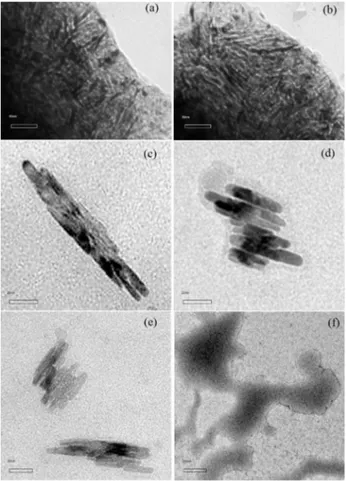
In the TEM characterisation (Figure 5), fibers or nanowires electrodeposited following the methodology described herein, with diameters ranging from 2.8 to 4.0 nm, can be observed.
From the pictures, it can be calculated that nanowires obtained from Th, BTh and TTh had ca. 25, 80 and 37 nm wire-length, respectively, an impressive low value considering the synthetic methods employed. It is also appreciated that as the starting unit chain length increases and electrosynthesis into confined spaces of the porous film is performed, the obtained polymer exhibits a higher order degree. The last statement is confirmed when comparing images with the ones of previous reports,13 proving the reproducibility of the methods when using different monomeric species.
Despite QTh deposits presenting non-reproducible results, there was some film formation (deposition with
Figure 5. TEM images of PTh electroobtained on Pt|(SiO2)n, after
treatment with HF:H2O for 5 s, using (a) and (b) Th; (c) BTh; (d) and (e)
TTh; and (f) QTh as a starting unit.
colour change within the electrode) evidence in the electrode. Nevertheless, in this case nanowire presence was not verified, possibly because deposition from long units within the pores is highly hindered and could not be appreciated by the employed techniques. In any case, in the images it is still possible to observe some presence of the template15 used to guide the polymer growth, therefore it is necessary to look into contact time and/or concentration or, in general, the methodology utilised for template removal.
Summarising, polythiophene nanowires can be synthesised using thiophene oligomers as starting units. This approach has advantages as requiring less oxidation potential preventing film overoxidation and, according to NGM discussion, the produced film would present a more homogeneous surface; both features desired for electronics design. These advantages were fully verified for Th, BTh and TTh deposits. However, the methods employed prevent the complete polymerisation when using QTh as starting unit, mainly due to the lower solubility of the oligomer and less adherence of the film.
Conclusions
Polymeric deposits have been electrosynthesised from Th, BTh, TTh and QTh on Pt and Pt|(SiO2)n electrodes, confirming that increase of the starting unit chain length yields more homogeneous layers, although this effect is limited since adhesion onto the electrode decreases.
Polythiophene deposited as nanowires improves macroscopic properties of the bulk deposits and promotes a charge increase of p-doping/undoping processes, because of the greater effective area of the nanostructured electrode.
The feasibility of electrosynthesising polymeric nanowires from different starting units, using only electrochemical techniques, has been corroborated. The current strategy enables validating and generalising the usefulness of the proposed methodology, pioneer and essential in an area where most applications of these kind of materials are determined by their morphology and requires deposition onto a supporting substrate. It only remains to establish or optimise strategies that enable the total removal of the template, to favour the nanostructured conformation of the modified electrode.
Acknowledgements
References
1. Tiwari, J.; Tiwari, R.; Kim, K.; Prog. Mater. Sci.2012, 57, 724. 2. Pan, L.; Qiu, H.; Dou, C.; Li, Y.; Pu, L.; Xu, J.; Shi, Y.; Int. J.
Mol. Sci.2010, 11, 2636.
3. del Valle, M. A.; Gacitua, M.; Diaz, F.; Armijo, F.; Soto, J.;
Electrochim. Acta2012, 71, 277.
4. Kantzas, T.; Semenikhin, O.; Electrochim. Acta 2011, 56, 3474. 5. Barth, S.; Hernandez-Ramirez, F.; Holmes, J.;
Romano-Rodriguez, A.; Prog. Mater. Sci.2010, 55, 563. 6. Li, C.; Bai, H.; Shi, G.; Chem. Soc. Rev.2009, 38, 2397. 7. McCullough, R.; Adv. Mater.1998, 10, 93.
8. Roncali, J.; Chem. Rev.1992, 92, 711.
9. Foroutani, K.; Pourabbas, B.; Sharif, M.; Mohammadizadeh, M.; Fallahian, M.; Khademi, S.; Mater. Sci. Semicond. Process.
2014, 18, 6.
10. Aradilla, D.; Estrany, F.; Casellas, F.; Iribarren, J. I.; Alemán, C.;
Org. Electron.2014, 15, 40.
11. Kim, F.; Ren, G.; Jenekhe, S.; Chem. Mater.2010, 23, 682. 12. Xia, L.; Wei, Z.; Wan, M.; J. Colloid Interface Sci.2010, 341,
1.
13. del Valle, M. A.; Gacitúa, M.; Díaz, F.; Armijo, F.; del Río, R.;
Electrochem. Commun.2009, 11, 2117.
14. del Valle, M. A.; Ramos, A. C.; Antilen, M. P.; Hernandez, L. A.; Arteaga, G. C.; Diaz, F. R.; Louarn, G.; Electrochemistry2014,
82, 146.
15. Walcarius, A.; Sibottier, E.; Etienne, M.; Ghanbaja, J.; Nat. Mater.2007, 6, 602.
16. Schrebler, R.; Grez, P.; Cury, P.; Veas, C.; Merino, M.; Gómez, H.; Córdova, R.; del Valle, M. A.; J. Electroanal. Chem.
1997, 430, 77.
17. del Valle, M. A.; Cury, P.; Schrebler, R.; Electrochim. Acta2002,
48, 397.
18. Romero, M.; del Valle, M. A.; del Río, R.; Díaz, F.; Armijo, F.;
Int. J. Electrochem. Sci.2012, 7, 10132.
19. Camarada, M. B.; Romero, M.; Giménez, M.; Schmickler, W.; del Valle, M. A.; Open J. Org. Polym. Mater.2013, 3,59.
20. del Valle, M. A.; Gacitúa, M.; Canales, L.; Díaz, F.; J. Chil. Chem. Soc.2009, 54, 260.
21. Soto, J.; Díaz, F.; del Valle, M. A.; Vélez, J.; East, G.; Appl. Surf. Sci.2008, 254, 3489.
22. del Valle, M. A.; Camarada, M. B.; Diaz, F.; East, G.; e-Polym.
2008, 72, 1.
23. Heinze, J.; Frontana-Uribe, B.; Ludwigs, S.; Chem. Rev.2010,
110, 4724.
24. Arteaga, G.; del Valle, M. A.; Antilén, M.; Romero, M.; Ramos, A.; Hernández, L.; Arévalo, M.; Pastor, E.; Louarn, G.;
Int. J. Electrochem. Sci.2013, 8, 4120.
25. Yeh, N.; Yeh, P.; Renewable Sustainable Energy Rev.2013, 21, 421.
26. Grevin, B.; Rannou, P.; Nat. Mater. 2004, 3, 503.
27. Huang, J.; Wang, K.; Wei, Z.; J. Mater. Chem. 2010, 20, 1117. 28. Kim, J.-H.; Kim, M.; Jinnai, H.; Shin, T. J.; Kim, H.; Park, J. H.; Jo, S. B.; Cho, K.; ACS Appl. Mater. Interfaces 2014, 6, 5640. 29. East, G.; del Valle, M. A.; J. Chem. Educ.2000, 77, 97. 30. Bewick, A.; Fleischmann, M.; Thirsk, H.; Trans. Faraday Soc.
1962, 58, 2200.
31. Zhao-yang, Z.; Yi-jie, T.; Xiao-qian, X.; Yong-jiang, Z.; Hai-feng, C.; Wen-wei, Z.; Synth. Met.2012, 162, 2176. 32. Monk, P.; Mortimer, R.; Rosseinsky, D.; Electrochromism:
Fundamentals and Applications; VCH: Weinheim, 1995. 33. Gratzl, M.; Hsu, D. F.; Riley, A. M.; Janata, J.; J. Phys. Chem.
1990, 94, 5973.
34. del Valle, M. A.; Canales, L.; Ramos, A.; Díaz, F.; Hernández, L.; Armijo, F.; Bernède, J.; Cattin, L.; Louarn, G.; Int. J. Electrochem. Sci.2013, 8, 1422.
35. Bewick, A.; Fleischmann, M.; Thirsk, H. R.; Trans. Faraday Soc. 1962, 58, 2200.
36. Xu, Z.; Horowitz, G.; J. Electroanal. Chem.1992, 335, 123. 37. Xu, Z.; Fichou, D.; Horowitz, G.; Garnier, F.; J. Electroanal.
Chem. Interfacial Electrochem.1989, 267, 339.
38. del Valle, M. A.; Ugalde, L.; del Pino, F.; Díaz, F.; Bernède, J.;
J. Braz. Chem. Soc.2004, 15, 272.
39. McCarthy, C.; McGuinness, N.; Alcock-Earley, B.; Breslin, C.; Rooney, A. Electrochem. Commun.2012, 20, 79.
40. del Valle, M. A.; Diaz, F. R.; Bodini, M. E.; Alfonso, G.; Soto, G. M.; Borrego, E. D.; Polym. Int. 2005, 54, 526.