Thomson Scattering Diagnostic on the ETE Tokamak:
Status and Progress
L. A. Berni, E. Del Bosco, R. M. Oliveira, and M. P. Alonso*
Instituto Nacional de Pesquisas Espaciais (INPE), Laborat ´orio Associado de Plasma (LAP), 12.227-010 S˜ao Jos´e dos Campos - SP, Brazil
*Associac¸˜ao EURATOM/IST, Centro de Fus˜ao Nuclear, 1049-001, Lisboa, Portugal
Received on 8 December, 2003; revised version received on 30 April, 2004
In order to measure the plasma temperature and density in the spherical tokamak ETE, a one-channel Thom-son scattering system was implemented. During the upgrade of capacitor banks and optimization since the beginning of operation, the plasma pulse duration has increased from 1.5 ms up to 12 ms with plasma currents varying from 10 kA to 60 kA. During this phase, the electron temperature was increased from 20 eV to 160 eV with densities as high as 3.5×10¹⁹m−3. Presently, the Thomson scattering diagnostic is being upgraded
based on the time-delay technique, that consists in using fibers of different lengths to transmit the scattered light signals to the same polychromator. This system will allow measurements of electron temperature and density profiles with ten spatial points per laser shot and per polychromator. This work describes in details the Thomson scattering system, presents a selection of results obtained by this system since the initial phase of operation, and shows details of the proposed upgrade of the Thomson scattering system.
1
The ETE Spherical Tokamak
The ETE (Experimento Tokamak Esf´erico) is a medium-size spherical torus with an aspect ratio of 1.5, major radius of 0.3 m, toroidal field of 0.4 T and plasma current of 0.22 MA for the first stage of operation [1]. The objectives of the pro-ject are focused on plasma edge investigation, development of diagnostics and training on tokamak operation.
The vacuum vessel was manufactured with Inconel 625 with an external diameter and height of 1.2 m and an inter-nal tube with a diameter of 0.18 m, which houses the ohmic solenoid and the inner legs of the toroidal coils. Good access for diagnostics is provided by 58 Conflat ports (12xCF14”, 4xCF250 and 42xCF40). The vacuum system comprises th-ree pumps: one turbo drag pump (1500 l/s) backed by an oil-free diaphragm (4 m3
/h) and an auxiliary mechanical pump (30 m3
/h). A base pressure of 7.8×10⁻⁸Torr was achieved after conditioning the vessel walls with baking (T<150o
C) and DC glow discharge cleaning (GDC) with helium gas.
There are three capacitor banks that storage energy for the toroidal, ohmic heating and equilibrium coils. The energy of the capacitor banks is being increased by adding more capacitors and increasing the maximum voltage rating. Presently, the acquisition system is based on CAMAC and oscilloscopes that, in a near future, will be replaced by VME technology [2].
Table 1 summarizes the status of the proposed diagnos-tics for ETE. For this initial phase a set of electromagne-tic and opelectromagne-tical diagnoselectromagne-tics are already installed. For edge plasma investigation a 10 keV Fast Neutral Lithium Beam (FNLB) is under development with glassy β-eucryptite source that will furnish beam currents up to 1 mA/cm2
[3]. To measure the electron temperature and density profiles
a one-channel Thomson scattering (TS) system was imple-mented.
2
Thomson Scattering Diagnostic in
ETE
TABLE 1: Status of the proposed diagnostics for ETE.
Diagnostic Status Parameters
1 Residual gas analyzer Installed Vacuum vessel conditioning 3 Rogowski coils Installed Toroidal, equilibrium and
ohmic currents
2 Rogowski coils (one inside the Installed Plasma and induced vessel
vessel) currents
12 Loop voltage coils (one inside the Installed Induced voltage and magnetic
vessel) flux
4 Bz/Brmagnetic pick up coils Installed MHD and magnetic field (protected by the graphite limiter)
2 (Bz, Brand BT) movable magnetic Installed MHD and magnetic field pick up coils (at the mid-plane)
1 Movable electrostatic probe (at the Installed Edge plasma mid-plane)
1 H-alpha detector with interference Installed H-alpha line behavior filter (∆λ= 13.52 nm)
1 Visible light spectrometer (12 ˚A/mm) Installed Impurity emission 1 CCD camera (500 FPS and shutter Installed Optical imaging
speed up to 1/10,000) (By loan)
1 Hard x-ray detector Installed Fast electrons
1 Thomson scattering system Installed Electron temperature and density profiles
1 Fast lithium beam probe Installed Edge plasma 1 CO2laser interferometer Planned Integrated density
Soft x-ray array Planned Electron temperature imaging
Electrostatic probes array Planned Edge plasma
Bolometers Planned Radiated power
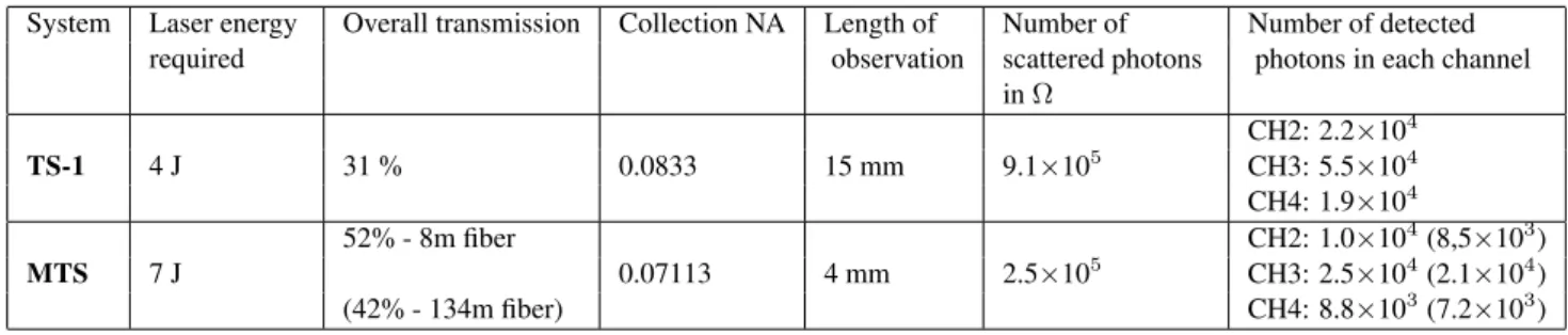
aluminum parts allowed a better vacuum vessel conditio-ning. An f/6.3 lens images the scattered light on a 7 m long fiber bundle with effective cross-section of 4.5x1.5 mm2
that is spectrally analyzed by a 5-channel filter polychromator. The present TS diagnostic was optimized to measure tem-peratures in the range of 20 to 2000 eV and densities greater than 1×10¹⁹m−3along 50 cm inside the plasma with a re-solution of 15 mm (shot by shot) [4]. For density measure-ments the TS was calibrated by rotational Raman scattering with nitrogen gas at pressures between 10 and 100 Torr.
3
Thomson Scattering Results in ETE
Figure 2 presents typical signals showing the evolution of the plasma current profile of ETE discharges until the last campaign of 2002. The first plasma was achieved at the end of 2000 with currents up to 12 kA and pulse duration of about 1.5 ms. The five profiles are representative of diffe-rent phases of operation.
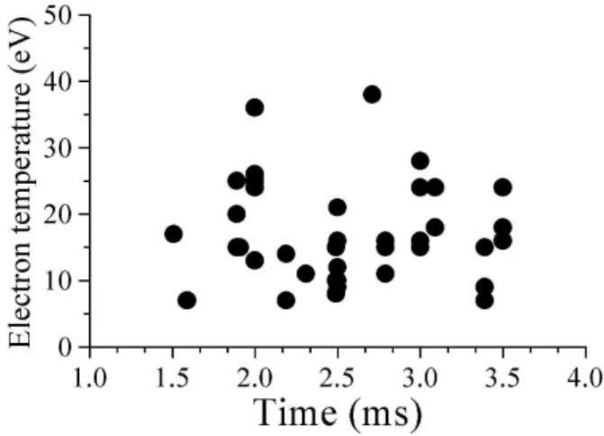
Figure 3 shows a collection of temperature values deter-mined by TS for different times in several discharges similar to shot #1881 (Fig. 2). Plasma currents of 25 kA lasting for 3.5 ms were achieved after the introduction of a new pair of ohmic heating coil in series with the existing ones, which reduced the stray field level. The maximum measured tem-perature was less than 40 eV for a radial position of 30 cm. Due to the high stray light level of the initial TS setup the measurements were restricted to R = 30 cm. As described in the previous section, modifications in the optical path of the laser beam and in the internal geometry of the dump reduced the stray light level in the TS system for shots starting from #2230.
Figure 2. ETE plasma evolution: #805 (28/11/2000): First plasma, #1881 (20/11/2001): After the ohmic heating improve-ments, #2529 (25/03/2002): After the external parameters optimi-zation, #3036 (25/11/2002): After the toroidal and ohmic banks upgrade, #3330 (27/12/2002): After the glow discharge cleaning.
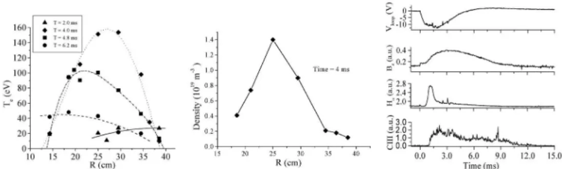
By optimizing the time delays, the voltage rating of the capacitor banks, the working gas parameters and by the va-cuum vessel conditioning due to the cleaning effect of the repetitive discharges, the plasma current reached up to 40 kA with typical time profile as shown in shot # 2529 (Fig. 2). Fig. 4 shows a set of diagnostics results including electron temperature and density profiles for these discharges. From
the temporal sequence of TS measurements (Figs. 4A and 4B) it can be observed that the plasma column compres-ses towards the central column achieving temperatures up to 160 eV and densities of 2.2×10¹⁹m−3. This shift of the plasma column to the position near R = 22 cm can be asso-ciated to high values of the vertical magnetic field necessary to compensate for the stray fields. The magnetic Bzprobe (Fig. 4C) placed at the mid-plane behind the graphite limiter of the vessel central column confirms the plasma shift as its signal increases during the discharge.
Figure 3. First electron temperature measurements (shots #1846 to #2057) with TS diagnostic (R = 30 cm) during the ETE discharge profiles as shot #1881 (see Fig. 2).
The plasma behavior represented by shot #3036 was ob-tained after increasing the energy of the toroidal and ohmic heating capacitor banks. Presently, the available energy of the banks are 300 kJ for the toroidal, 270 kJ for the ohmic heating and 27 kJ for the equilibrium. These values repre-sent approximately 1/4 of the total energy expected for the initial stage of operation (Ip≈200 kA). Fig. 5 (A and B) pre-sent Teand nesignals at 4.5 ms after the breakdown of the plasma. The results show that the density increased up to 3.5×10¹⁹ m−3. Each measurement is an average over th-ree shots and errors of +/- 7% can be considered when not indicated.
After about 30 hours of baking at temperatures less than 150o
C and 10 hours of GDC with Helium gas at currents of approximately 15µA/cm2
TABLE 2: Comparison between the present TS diagnostic (TS-1) and the proposed multipoint system (MTS).
System Laser energy Overall transmission Collection NA Length of Number of Number of detected required observation scattered photons photons in each channel
inΩ
CH2: 2.2×10⁴
TS-1 4 J 31 % 0.0833 15 mm 9.1×10⁵ CH3: 5.5×10⁴
CH4: 1.9×10⁴
52% - 8m fiber CH2: 1.0×10⁴(8,5×10³)
MTS 7 J 0.07113 4 mm 2.5×10⁵ CH3: 2.5×10⁴(2.1×10⁴)
(42% - 134m fiber) CH4: 8.8×10³(7.2×10³)
Figure 4. Radial electron temperature (A) and density (B) measurements (shots #2461 to #2551) for different times during discharges like #2529 (see Fig. 2). (C) Typical signals of: Vloop - Loop voltage, Bz- Magnetic probe, CIII - Carbon III emission and Hα- Hydrogenα
emission.
Figure 5. Electron temperature (A) and density (B) measurements, respectively, for the discharge as shot #3036 (see Fig. 2) at 4.5 ms.
4
Fiber optic multiplex upgrade of
the Thomson scattering
A multipoint Thomson scattering (MTS) diagnostic based on the time-delay technique is being proposed to upgrade the present system. This MTS system consists in using se-veral optical fibers of different lengths to transmit the light signals to the same polychromator [5][6]. The proposed sys-tem uses monofibers with a core diameter of 0.8 mm and NA = 0.39. These fibers present an average attenuation of 7 dB/km in the spectral range from 694 nm to 880 nm. Be-cause the effective area of the detection system is limited to 7 mm2
Figure 6. Electron temperature (A) and density (B) profiles after glow discharge cleaning as shot #3330 in Fig. 2. Other diagnostics (C): Vloop - Loop voltage, Bz- Magnetic probe, Hα- Hydrogenαemission and CIII - Carbon III emission.
Figure 7. First tests with fibers for the MTS system. A) Ruby laser pulses. B) Normalized signals at the end of 8 m (left) and 112 m (right) fibers.
Figure 7 shows that the measured time delay between a fiber of 8 m and a fiber of 112 m is 512 ns, that is very near to the calculations (504 ns). Although the absolute value of attenuation has not been measured, Fig. 7B shows that the peak value of the signal of the longest fiber is 61% of the shortest one, which is less than the estimated value of 84%. This difference is due to the time dispersion of light signals that is proportional to the diameter and the length of the fi-ber. Note that, the transmission must be measured by the ratio of the areas under the signals, which is in agreement with the calculations. These tests were performed using the ruby laser beam attenuated by diffusers and filters.
5
Conclusions
The TS measurements show that the diagnostic was success-fully implemented presenting a very stable alignment setup.
Other improvements in the flight tube and in the dump are under way to reduce even more the stray light levels. With the one-channel TS it is necessary more than one hundred shots to obtain the density and temperature profiles, which takes time and makes difficult the interpretation of the re-sults. For these reasons a multipoint TS system using the multiplexed technique was planned. The MTS will allow si-multaneous measurements of ten spatial points in a single ETE discharge using only one polychromator. The first tests with fibers to be used in the MTS showed good agreement with the calculations and tests with four channels are being prepared.
Acknowledgements
This work was partially supported by the Fundac¸˜ao de Amparo `a Pesquisa do Estado de S˜ao Paulo (FAPESP). The participation of M. P. Alonso in this project has been sup-ported by the Contract of Association between the European Atomic Energy Community and Instituto Superior T´ecnico.
References
[1] G. O. Ludwig, E. Del Bosco, J. G. Ferreira, et al, Braz. J. Phys.33, 4 (2003).
[2] R. M. Oliveira, F. L. W. Barbosa, J. G. Ferreira, and C. S. Shibata, Fusion Eng. and Design60, 403 (2002).
[3] R. M. Oliveira, M. Ueda, and W. A. Vilela, Braz. J. Phys.32, 1 (2002).
[4] L. A. Berni, M. Ueda, E. Del Bosco, et al, Rev. Sci. Instrum.
74, 1200 (2003).
[5] M. P. Alonso, P. D. Wilcock, and C. A. F. Varandas, Rev. Sci. Instrum.70, 783 (1999).
[6] M. P. Alonso, L. A. Berni, and E. Del Bosco, in 30th EPS Conference on Controlled Fusion and Plasma Physics, St. Pe-tersburg, Russia, 2003.