System–Level Evaluation of Space–Time
Processing for EDGE
A. L. F. de Almeida, F. R. P. Cavalcanti, C. E. R. Fernandes, J. C. M. Mota, W. M. de Sousa Jr.
GTEL–UFC, Wireless Telecom. Research Group, Federal University of Cear´a, Fortaleza, Brazil
{andre,rod,estevao,mota,waltemar}@gtel.ufc.br
URL:http://www.gtel.ufc.br
Abstract—In this work we perform a system-level evaluation of conventional and decoupled space-time processing strategies for the enhanced data rates for global evolution (EDGE) system. The main idea of decoupled space-time (D–ST) processing is to en-hance the performance of the temporal equalizer by separating co-channel interference (CCI) reduction from inter-symbol interfer-ence (ISI) suppression in two stages. Here, we employ a DDFSE as the temporal equalizer, which is a promising reduced-complexity equalization scheme for EDGE. In this contribution, the bit er-ror rate (BER) performance of D–ST–DDFSE is accessed at both link- and system-levels. Concerning the system-level evaluation, an estimation of the output signal-to-interference-ratio (SIR) is performed for different load conditions and channel profiles such as the COST259 typical urban (TU) and bad urban (BU). Our ob-jective is to show the potential gains of space-time processing in EDGE for extremely tight reuse patterns.
I. INTRODUCTION
I
N high-data rate mobile communications, co-channelinter-ference (CCI) and intersymbol interinter-ference (ISI) are key fac-tors that limit performance and capacity. In the incoming third generation systems as the enhanced data rates for GSM Evo-lution (EDGE) [1], [2], large delay spread causes a significant distortion on the transmitted signal. The presence of strong CCI further contributes to degrade signal quality and system capac-ity. Space-time processing techniques are crucial in overcoming the problems caused by ISI and CCI in practical propagation environments characterized by rich multipath. A space-time linear equalizer (ST–LE) is characterized by the inclusion of a temporal filter at each antenna, which allows exploiting both spatial and temporal diversity of the received signal to cancel ISI and CCI [3].
However, simultaneous ISI and CCI mitigation may degrade equalizer performance, since the the difference on the charac-teristics of ISI and CCI may cause space-time (ST) algorithms based on the minimum mean square error (MMSE) criterion to combat ISI more, thus causing the presence of residual CCI at the input of the equalizer. Furthermore, ISI-dominated scenar-ios with small values of angular separation among user paths may severely reduce output SINR and degrade bit-error-rate (BER) performance. Thus, it is reasonable to state that it would be desirable to treat ISI with an MLSE equalizer, which is the
This work is supported by the Ericsson Research–Brazilian
Branch under the ERBB/UFC.01 Technical Cooperation Contract.
URL:http://www.ericsson.ufc.br
optimum detector in the presence of ISI. Similarly, CCI is better combated with an MMSE equalizer.
A decoupled space-time (D–ST) processing technique [4], [5], [6] can make use of the individual advantages of an ST-MMSE-based algorithm for CCI reduction and an MLSE-based algortihm for ISI supression. This is done by separating CCI
and ISI mitigation in two stages. Based on a joint
opti-mization criterion, the ST front-end and a channel estimator filter are jointly adapted, attempting to maximize the signal-to-interference-plus-noise-ratio (SINR) at the output of the ST front-end, thus preserving all ISI structure of the desired signal to be dealt with the MLSE-based temporal equalizer without noise enhancement.
In this paper we evaluate two ST processing strategies on both CCI and ISI-limited scenarios. The first one is a space-time DDFSE (ST–DDFSE), which consists of a ST-MMSE front-end followed by a DDFSE equalizer [7], [8]. The second one is a decoupled space-time (D–ST) structure that also em-ploys a DDFSE equalizer (D–ST–DDFSE), which is a promis-ing reduced-complexity equalizer for EDGE. Comparisons be-tween the two aforementioned ST processing structures are done at both link and system-levels in an integrated manner. Some D–ST structures have been proposed and evaluated at the link-level in our recent contributions [9], [10] on the contexts of TDMA IS–136 and EDGE. In this contribution, the BER and SIR performances of ST–DDFSE and D–ST–DDFSE are evaluated on typical urban (TU) and bad urban (BU) profiles of the COST259 channel model. Our objective is to show the potential gains of space-time processing in EDGE.
In the remainder of this paper, we organize the sections as follows. In section II, the ST–DDFSE and D–ST–DDFSE structure are briefly presented. In section III, we show link-level simulations results of ST–DDFSE and D–ST–DDFSE for COST259 TU and BU scenarios under controlled conditions. Our system simulator is presented in section IV. In section V, system-level simulations results are presented. At last, in sec-tion VI, we draw our conclusions.
II. SPACE–TIMEEQUALIZER
Figure 1(a) shows a receiver structure that implements a ST–
DDFSE. A space-time filter of N antenna elements and M
ADAPTATION
MLSE
FEEDBACK FILTER DDFSE EQUALIZER
decided sequence
– +
SPACE-TIME LINEAR FILTER
1
2
N
+ _
training sequence
(a) ST–DDFSE.
DDFSE EQUALIZER
∑
TEMPORAL ISI SUPRESSION
1
+
2
N
SPACE TIME
LINEAR FILTER MLSE
FEEDBACK FILTER
–
SPACE-TIME CCI REDUCTION
JOINT ADAPTATION CHANNEL ESTIMATOR
FILTER
+
–
decided sequence
training sequence
error signal
computed equalizer coefficients
(b) D–ST–DDFSE.
Fig. 1. Space-time processing structures
it can be seen as a feedforward section of a decision-feedback equalizer (DFE). The feedback section “shortens” the channel impulse response seen by the MLSE portion of the DDSFE in order to reduce its computational complexity. In Fig. 1(b) the structure of the D–ST–DDFSE is shown. A finite impulse re-sponse (FIR) filter has the training sequence as its input and its output is subtracted from the output of the ST filter. The coefficients of the ST filter and that of the FIR filter are jointly adapted so that, after convergence, only co-channel interference is cancelled at the ST filter and at its output, only ISI is present. The coefficients of the FIR filter are the taps of the estimated channel impulse response that provide channel state informa-tion to the DDFSE equalizer.
The vector of coefficients of the ST filter is denoted by
W = wT
1 wT2 . . . wTM
T
, wherewi = [wi1wi2 . . . wiN]T,
and h = [h1h2. . . hL]T are the coefficients of the FIR
filter. The vector of received samples is denoted by X =
xT
1 xT2 . . .xTM
T
, wherexi = [xi1xi2 . . . xiN]T andd =
[d1d2 . . . dL] T
is the vector of training symbols and the input
of the FIR filter. The optimum solution for bothWandh
max-imizes the SINR at the output of the antenna array as defined below:
(wopt,hopt) = arg max w,h SINR
= arg max
w,h
WHX
WHX−hHd2. (1)
One possible solution to the maximization of (1) corresponds to the minimization of the following cost function
J(W,h) =WHX−hHd2 (2)
subject tocTh= 1,c= [0 . . . c
j . . .0],cj = 1[6]. The FIR
filter is initialized by setting one of its tapshj equal to one,
which is called the reference tap. The choice of the position of the reference tap determines the equalizer delay and thus, it is
4 6 8 10 12 14 16 18 20
10−6 10−5
10−4 10−3
10−2 10−1
Eb/No (dB)
BER
ST−DDFSE 2−branch, 1 tap/branch D−ST−DDFSE, 2−branch, 1 tap/branch ST−DDFSE 2−branch, 3 tap/branch D−ST−DDFSE, 2−branch, 3 tap/branch ST−DDFSE 3−branch, 2 tap/branch D−ST−DDFSE, 3−branch, 2 tap/branch
TU
Fig. 2. BER performance of ST–DDFSE and D–ST–DDFSE on TU profile for different configurations of the ST front-end.
crucial for a good performance of the D–ST technique. During the training period, the reference tap identifies the number of causal and anticausal taps of the estimated channel impulse re-sponse and it should be kept equal to one. After training, the taps of the FIR are employed as the coefficients of the temporal equalizer, which in this work is a DDFSE.
The order of the channel estimator should be sufficiently large to capture the most delayed paths of the desired user. On the contrary, ISI due to the most delayed paths are supressed by the ST front-end along with CCI.
III. LINK–LEVELPERFORMANCE
4 6 8 10 12 14 16 18 20 10−3
10−2
10−1
Eb/No (dB)
BER
ST−DDFSE 2−branch, 1 tap/branch D−ST−DDFSE, 2−branch, 1 tap/branch ST−DDFSE 2−branch, 3 tap/branch D−ST−DDFSE, 2−branch, 3 tap/branch ST−DDFSE 3−branch, 2 tap/branch D−ST−DDFSE, 3−branch, 2 tap/branch
HT
Fig. 3. BER performance of ST–DDFSE and D–ST–DDFSE on HT profile for different configurations of the ST front-end.
channel profile. We assume the channel is static over a interval of a slot. Each run represents a transmitted time-slot of 140 symbols from which 26 are for training. The pulse shaping function is a raised cosine with 35% roll-off. Besides, we use 8–PSK modulation since our system context is EDGE. The recursive least squares (RLS) algorithm is used for adapta-tion. The channel estimator has 4, 8 and 3 taps on TU, HT and RA channel profiles, respectively. Concerning the MLSE por-tion of DDFSE, we work with a 1-state Viterbi, in a reduced-complexity approach. The feedback scheme of DDFSE em-ploys 3, 7 and 2 taps for TU, HT and RA respectively. For the TU profile, it is shown in Fig. 2 that the D–ST–DDFSE is supe-rior to ST–DDFSE in most situations. Note that the 2-branch D–ST–DDFSE with 3 taps/branch outperforms the 3-branch
ST–DDFSE with 2 taps/branch for medium to highEb/N0
val-ues. Fig. 3 shows the results for the HT profile. Here, the per-formance improvement of D–ST–DDFSE is observed for the 3-branch case, only. In the RA profile the performances of D–ST–DDFSE and ST–DDFSE are nearly the same for the 2-branch case with 1 and 2 temporal taps per 2-branch, while for the 3-branch case, some performance improvement of D–ST– DDFSE is verified. This is clear from Fig. 4.
IV. SYSTEM–LEVELSIMULATOR
A system-level simulator of the reverse link of an EDGE sys-tem was built in order to evaluate the performance of D–ST– DDFSE at the system-level. A brief description of the static in-tegrated link–system simulator for EDGE is as follows. Users are uniformly distributed within the cells, where data is col-lected from the central one. The 1/1 and 1/3 reuse patterns are sought. A uniform linear antenna array is employed in each of the three sectors where the standard UMTS sector antenna pat-tern is superimposed over the array patpat-tern. Two rings of CCI are considered in both reuse cases. Uplink signal-level power control is based on standardized maximum and minimum mo-bile station transmission power [11]. The link-budget model prescribed by UWCC [12] is adopted, which gives slightly
4 6 8 10 12 14 16 18 20
10−8 10−7
10−6
10−5
10−4 10−3 10−2 10−1
Eb/No (dB)
BER
ST−DDFSE 2−branch, 1 tap/branch D−ST−DDFSE, 2−branch, 1 tap/branch ST−DDFSE 2−branch, 3 tap/branch D−ST−DDFSE, 2−branch, 3 tap/branch ST−DDFSE 3−branch, 2 tap/branch D−ST−DDFSE, 3−branch, 2 tap/branch
RA
Fig. 4. BER performance of ST–DDFSE and D–ST–DDFSE on RA profile for different configurations of the ST front-end.
TABLE I
SYSTEM-LEVEL SIMULATION PARAMETERS.
Cell Multicell grid, 1/3
Layout or 1/1, sector patterns
Sector Antenna Gain 13 dBi
Mobile Antenna Gain 0 dBi
Path-loss Model 35log(d)+shad. [dB]
Shadowing Standard Deviation 8 dB
Cell Radius 500 m
Uplink Power Control Yes
Uplink Max. Transmission Power 28 dBm
Uplink Min. Transmission Power -7 dBm
Frequency 1800 MHz
Symbol Rate / Modulation 270.833 Kbaud
Desired Received Power at Base -102 dBm
Noise Power Density - 174 dBm/Hz
Noise Figure 5 dB
more pessimistic interference levels when compared to the rec-ommended UMTS path loss model. The modulation scheme, slot format and symbol rate used in all simulations follows those of the EDGE system. RLS-like adaptation is employed and the average output SIR of the space-time processing struc-tures is approximated from the raw BER, using an inverse link-to-system level mapping. System-level simulation parameters are detailed in table I.
An important feature of this simulator is the employment of the COST 259 [13] for realistic simulations. The COST 259 is a wideband directional channel model capable of providing chan-nel impulse responses in both spatial and temporal domains and it was validated using measurements in the 1GHz to 2GHz range. In this work we use a two-step procedure to generate the received signal. The users distribution is the input of both the
link-budget algorithm, whose outputs are the SIR andEb/N0
100% 75% 50% 25% 10−3
10−2 10−1
load factor
raw BER
ST−DDFSE − 1/1 reuse D−ST−DDFSE − 1/1 reuse ST−DDFSE − 1/3 reuse D−ST−DDFSE − 1/3 reuse
Fig. 5. BER performance at system-level of ST–DDFSE and D–ST–DDFSE
on TU profile for slot-synchronized users.
V. SYSTEM–LEVELEVALUATION
In this section we evaluate the BER performance of ST– DDFSE and D–ST–DDFSE at system-level on the TU and BU channel profiles of COST 259. The results are averaged over 2000 snapshots of the static system simulator from which we
collect the SIR andEb/N0statistics and the channel impulse
responses for all users on the grid. We consider the possibility that the co-channel interferers are not slot-synchronized with the desired user. Ideal frequency hopping is assumed so that Rayleigh fading envelopes and positions of a given user in ad-jacent time-slots are independent. We consider also 4 different channel usage (load) factors, say, 25%, 50%, 75% and 100%. This load factor can be interpreted as the probability of channel occupation or the fractional load factor.
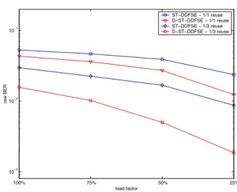
For a given target uncoded BER, the capacity gains exper-imented by the D–ST equalizer in COST 259 scenarios with tight reuse patterns and non-synchronized users/base-stations will be illustrated. The two space-time processing structures employ 4 receive antennas with 3 temporal taps at each antenna. In Fig. 5 we verify that the D–ST–DDFSE exhibits the best per-formance on TU profile with 1/1-reuse and slot-synchronized users. The D–ST structure can provide a capacity gain of about 37%, compared to the ST–DDFSE, at a target uncoded BER of 3%.
If 1/3 reuse is employed instead of 1/1 reuse the capacity gain is about 50% at a target uncoded BER of 1%. For BU profile, Fig. 6 shows that such a gain is about 22% for 1/1 reuse and 45% for 1/3 reuse, at 3% and 1% BER, respectively. Still in Fig. 5, the capacity gain of the D–ST structure can be verified in another way. At a load factor of about 38%, the D-ST-DDFSE with 1/1 reuse exhibits the same BER perfor-mance than the ST-DDFSE with 1/3 reuse, a three-fold capac-ity increase, demonstrating the D–ST–DDFSE is well suited to scenarios with strong CCI. By comparing Fig. 5 and Fig. 6 we can make some observations concerning the performance of both space-time structures on TU and BU profiles for 1/1 reuse. In order to keep the BER at 3%, the D–ST–DDFSE re-quires a more aggressive load reduction than the ST-DDFSE does, on BU profile. However, for 1/3 reuse this is not verified
100% 75% 50% 25%
10−3 10−2 10−1
load factor
raw BER
ST−DDFSE − 1/1 reuse D−ST−DDFSE − 1/1 reuse ST−DDFSE − 1/3 reuse D−ST−DDFSE − 1/3 reuse
Fig. 6. BER performance at system-level of ST–DDFSE and D–ST–DDFSE
on BU profile for slot-synchronized users.
100% 75% 50% 25%
10−3
10−2
10−1
load factor
raw BER
ST−DDFSE − 1/1 reuse D−ST−DDFSE − 1/1 reuse ST−DDFSE − 1/3 reuse D−ST−DDFSE − 1/3 reuse
Fig. 7. BER performance at system-level of ST–DDFSE and D–ST–DDFSE
on TU profile for non slot-synchronized users.
and the same performance difference between both space-time structures is kept.
Considering non-synchronized users, for the TU profile the D–ST–DDFSE still outperforms its conventional counterpart. We verify that the capacity gain is more pronounced on 1/3 reuse. This is shown in Fig. 7. Comparing Fig. 5 and Fig. 7 it can be seen that the performance of D–ST–DDFSE dimin-ishes compared to the ST–DDFSE in this asynchronous case. However a capacity gain of almost 20% is still verified at 3% raw BER for 1/1 reuse. From Fig. 8, where the BU profile is considered, we observe that the results remain almost un-changed, indicating that the slot-asynchronism is a key factor on the performance degradation of the considered space-time structures. Next, we evaluate the performance of the space-time processing structures in terms of output SIR. The inverse link-to-system level mapping was obtained from a simulator of the physical layer of EDGE, which employs the Modulation and Coding Scheme 7 [14].
100% 75% 50% 25% 10−3
10−2 10−1
load factor
raw BER
ST−DDFSE − 1/1 reuse D−ST−DDFSE − 1/1 reuse ST−DDFSE − 1/3 reuse D−ST−DDFSE − 1/3 reuse
Fig. 8. BER performance at system-level of ST–DDFSE and D–ST–DDFSE
on BU profile for non slot-synchronized users.
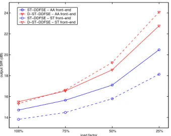
estimate of the EDGE radio link control (RLC) block SIR, which can then be translated into throughput. Fig. 9 shows output SIR results. The gain of D–ST–DDFSE over ST–DDFSE can be as much as 6 dB for low loading factor of 25% and when comparing the best and worst configuration of each one. This gain can be translated into a rough throughput gain of 14 Kbps when the average SIR goes from 18 dB to 24 dB and when pure ideal link adaptation is used in EDGE [14].
100% 75% 50% 25% 14
16 18 20 22 24
load factor
output SIR (dB)
ST−DDFSE − AA front−end D−ST−DDFSE − AA front−end ST−DDFSE − ST front−end D−ST−DDFSE − ST front−end
Fig. 9. Output SIR of ST–DDFSE and D–ST–DDFS on TU profile for non
slot-synchronized users: AA front-end and ST front-end.
Some performance degradation of ST–DDFSE is verified for the ST front-end case. We observed such degradation occurs for scenarios limited by CCI and ISI, for a limited numbers of antennas. In this case, a considerable amount of residual CCI at the input of the DDFSE equalizer degrades its performance. Since the D–ST structure tries to mitigate CCI at the ST front-end, less amount of residual CCI is present at the input of the temporal equalizer and the use of a ST front-end gives some performance improvement.
VI. CONCLUSIONS
We have evaluated the performance of D–ST–DDFSE through both link-level and system-level simulations. Link-level simulations on the TU, HT and RA GSM channel profiles with a single CCI have indicated that D–ST–DDSFE outper-formed its conventional counterpart. On TU profile, with only 2 branches and 3 taps/branch, the D–ST–DDFSE has presented the same, or an even better performance than the ST–DDFSE with 3 branches and 2 taps/branch. On HT and RA profiles, the performance improvement of D–ST–DDFSE was observed only when 3 branches were used. Concerning the system-level simulations on the TU and BU profiles of the COST 259 chan-nel model, we have shown that the D–ST–DDFSE may pro-vide substantial capacity gains compared to the ST–DDFSE. We have also verified that the slot-asynchronism degraded the performance of both space-time structures, as expected. In this case there was no expressive difference in performance consid-ering the TU and BU profiles. Even in the asynchronous case, a capacity gain in terms of fractional loading factor of almost 20% in the 1/1 reuse pattern was verified for D–ST–DDFSE. Finally, the D–ST–DDFSE provided a SIR gain of almost 6dB, compared to the ST–DDFSE, on a TU scenario with 1/1 reuse. This can be roughly translated into a throughput gain of 14 dB.
REFERENCES
[1] ETSI TS 100 573,Digital cellular telecommunications system (Phase
2+); Physical layer on the radio path; General description, (GSM 05.01 version 8.4.0 Release 1999).
[2] ETSI EN 300 959,Digital Cellular Telecommunications System (Phase
2+); Modulation, (GSM 05.04 version 8.1.0 Release 1999).
[3] A. J. Paulraj, and C. B. Papadias, “Space-Time Processing for Wireless
Communications”, IEEE Signal Processing Magazine, Vol. 14, No. 6,
pp. 49–83, Nov. 1997.
[4] S. Fanfoni, D. Giancola, U. Girola, S. Parolari, A. Picciriello, and U. Spagnolini, “Space-Time Processing for Co-Channel Interference
Rejec-tion and Channel EstimaRejec-tion in GSM/DCS Systems”,Proc. of URSI
In-tern. Symp. Sig., Syst., and Elect., ISSSE 98, pp. 152-155, 1998.
[5] J.W. Liang, Interference Reduction and Equalization with Space-Time
Processing in TDMA Cellular Networks. Ph.D. thesis, Stanford Univer-sity, June 1998.
[6] M. L. Leou, C. C. Yeh, and H. J. Li, “A Novel Hybrid of Adaptive
Ar-ray and Equalizer for Mobile Communications”,IEEE Transactions on
Vehicular Technology, Vol. 49, No. 1, pp. 01–10, Jan. 2000.
[7] A. Duel-Hallen, and C. Heegard, “Delayed Decision-Feedback Sequence
Estimation”, IEEE Transactions on Communications, Vol. 37, No. 5,
pp. 428–436, May 1989.
[8] S. L. Ariyavisitakul, J. H. Winters, and N. R. Sollenberger, “Joint Equal-ization and Interference Suppression for High Data Rate Wireless
Sys-tems”, IEEE Journal on Selected Areas in Communications, Vol. 18,
No. 7, pp. 1214–1220, July 2000.
[9] C. M. Panazio, and F. R. P. Cavalcanti, “Decoupled Space–Time
Pro-cessing: Performance Evaluation for a TDMA System”,Proc. of IEEE
Vehicular Technology Conference, Fall’01, 2001.
[10] A. L. F. de Almeida, C. M. Panazio, F. R. P. Cavalcanti, and C. E. R. Fer-nandes, “Space–Time Processing with a Decoupled Delayed Decision–
Feddback Sequence Estimator”,IEEE Vehicular Technology Conference,
Spring’02, 2002.
[11] ETSI TS 100 910,Digital Cellular Telecommunications System (Phase
2+); Radio Transmission and Reception, (3GPP TS 05.05, version 8.9.0 Release 1999).
[12] TIA/EIA-136-000-B,TDMA Third Generation Wireless, March 2000.
[13] L. M. Correia,Wireless Flexible Personalized Communications, COST
259: European Co-operation in Mobile Radio Resource, Wiley 2001. [14] D. Molkdar, and S. Lambotharan, “Link Performance Evaluation of
EG-PRS in LA and IR Modes”,Proc. of IEEE Vehicular Technology