ISSN 1546-9239
© Science Publications, 2005
Improving the Quality of Ceramic and
Cemented Carbide Cutting Inserts by Diamond Grinding
Tareq Ahmad Abu Shreehah and Rasheed Abdulateef Abdullah
Department of Mechanical Engineering, Al-Balqa’ Applied University, Jordan
Abstract: The machining of hardened steel and other difficult-to-cut materials require high quality and progressive cutting tools to meet the growing requirements for increasing productivity, improving tool life and quality of the cutting process. This study deals with an experimental investigation on the quality improvement by diamond grinding of ceramic and cemented carbide cutting inserts, comparing it with conventional batch produced types. It was found that under finish turning of hardened up to 61 HRC steel the ground cutting inserts improve the machined surface finish, reduce tool wear and breakage and subsequently extend the tool life.
Key words: Finish Turning, Ceramic, Carbide, Tool Life, Surface Finish
INTRODUCTION
The cutting tool is considered as an important factor on which the quality and productivity of the cutting manufacturing process depend on. The efficiency of the cutting tool, defined by its serviceability at maximum possible tool life, depends mainly on the material on the tool working part. The application of such tool material in concrete manufacturing conditions depends[1] on the tool and machine tool service function, the required effectiveness of the machining process, the relevant quality and accuracy of the machined surfaces and on the work piece type and material.
The proper choice of the material for tool manufacturing is one of the major conditions for its high productive working. The best material is the one that will produce the machined part at lowest cost[2]. The ceramic and cemented carbide tools may be recommended[3, 4] for finish and semi-finish cutting of hardened steel and difficult-to-cut structural materials.
During machining[5-8] the edges of the cutting tool are subject to high pressure, friction and high temperatures that cause premature failure of the tool or gradual wear. The catastrophic failure[6, 7] of the tool by which it falls suddenly may be due to the higher temperature at which the tool loses its hardness and becomes dull. This type of sudden failure is known as thermal softening. Moreover, the premature failure of the cutting tool may be due to the breakage or fracture and separation of the cutting edge, that occur in tools mechanically weak to resist the cutting force and brittle. Thus, premature failure is a problem of all brittle materials, especially ceramics.
In the process of metal cutting under the normal conditions, the cemented carbide tool is subjected to gradual wear and failed progressively. The most effective tool flank wear on machining is usually due to[7] both abrasive and adhesion mechanisms.
The efficiency of the machining process and its quality depend on the insert cutting edges and surface state, particularly in the presence of notches, spellings and the surface roughness of the tool face and flank. The objective of this research is to evaluate the effectiveness of diamond-ground carbide and ceramic inserts in improving the machined surface finish and tool life during finish turning of hardened steel of 61 HRC.
EXPERIMENTAL PROCEDURE AND TESTS
Machining Test: All external finish turning tests were carried out on a rigid Colchester Student 1800 engine lathe under the conditions shown in Table 1. Coolant was used throughout the turning test.
Work Piece Material: Finish turning trials were carried on a smooth circular bar of high carbon and high chromium alloy tool steel Sverker 21. For revealing the cutting capabilities of the inserts, the workplace was heat-treated to hardness of 61 HRC. The composition and properties of the work piece are stated in Table 2.
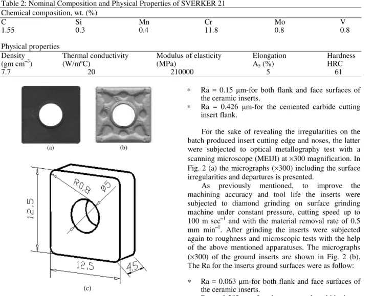
Cutting Inserts: Cemented carbide and ceramic inserts of square shape were used. The photographs and geometry of both inserts are shown in Fig. 1. The inserts were clamped mechanically to a standard cutter to provide the cutting geometry as given in Table 1. The composition and properties of the insert materials are also adduced in Table 1.
American J. Applied Sci., 2 (5): 969-975, 2005
970
Table 1: Characteristic of the Cutting Inserts and Finish Turning Test Conditions
Type of inserts used 1. Batch produced uncoated cemented tungsten titanium carbide and oxide carbide ceramic
2. Diamond-ground uncoated cemented tungsten titanium carbide and oxide carbide ceramic
Composition and properties of the cutting inserts
Transverse rupture Insert type Base elements Density (gm cm3) Hardness (HRA) strength (MPa) Oxide carbide ceramic AL2O3 ≥ 60%, TiC < 40% 4.2-4.3 93-94 550-700
Cemented carbide 97%WC-3%Co 12-Oct 85-92 1590
Side cutting edge angle = 45° Cutting geometry Back rake angle = -5°
End relief angle = 8°
Cutting conditions: For ceramic inserts For carbide inserts
Cutting speed, υ (m min1) 90; 120; 150 and 180 60; 90 and 120
Feed rate, f (mm rev1) 0.05; 0.1 and 0.15 0.05; 0.1 and 0.15
Depth of cut, t (mm) 0.5; 0.75 and 1 0.5; 0.75 and 1
Cooling fluid Mineral oil emulsion
Table 2: Nominal Composition and Physical Properties of SVERKER 21 Chemical composition, wt. (%)
C Si Mn Cr Mo V
1.55 0.3 0.4 11.8 0.8 0.8
Physical properties
Density Thermal conductivity Modulus of elasticity Elongation Hardness
(gm cm3) (W/mºC) (MPa) A5 (%) HRC
7.7 20 210000 5 61
(a) (b)
(c)
Fig. 1: (a) Ceramic (b) Cemented carbide (c) The Geometry of the Inserts. Images and Geometry of the Ceramic and Cemented Carbide Inserts Used
∗ Ra = 0.15 m-for both flank and face surfaces of the ceramic inserts.
∗ Ra = 0.426 m-for the cemented carbide cutting insert flank.
For the sake of revealing the irregularities on the batch produced insert cutting edge and noses, the latter were subjected to optical metallography test with a scanning microscope (MEIJI) at ×300 magnification. In Fig. 2 (a) the micrographs (×300) including the surface irregularities and departures is presented.
As previously mentioned, to improve the machining accuracy and tool life the inserts were subjected to diamond grinding on surface grinding machine under constant pressure, cutting speed up to 100 m sec1 and with the material removal rate of 0.5 mm min1. After grinding the inserts were subjected again to roughness and microscopic tests with the help of the above mentioned apparatuses. The micrographs (×300) of the ground inserts are shown in Fig. 2 (b). The Ra for the inserts ground surfaces were as follow:
∗ Ra = 0.063 m-for both flank and face surfaces of the ceramic inserts.
∗ Ra = 0.203 m-for the cemented carbide insert flank.
971
(a) The Magnified Illustrations of the Unground Cutting Edge and Inserts Nose
(b) The Magnified Illustrations of the Ground Cutting Edge and Insert Nose
American J. Applied Sci., 2 (5): 969-975, 2005
972
(a) By Turning with Conventional Batch Produced Inserts
(b) By Turning with Diamond Ground Inserts
Fig. 3: The Relationship between the Cemented Carbide Tool-Life and the Cutting Speed
Tool Life and Machined Surface Finish: Both ground and underground ceramic and cemented carbide inserts were examined. The carbide insert flank wear at various stages of each test using a microscope was fixed. Carbide insert rejection or failure was determined according to the flank wear for finish processing ranges from 0.4 to 0.6 mm[1]. The ceramic inserts work until fracture.
Data on tool life when turning using different inserts are shown in Fig. 3 and 4. The growth of carbide flank wear was significantly reduced by employing the lowest cutting speed of 60 m min1. As the cutting speed increases and the heat generated at the tool-work contact area becomes elevated as the insert loses its hardness and strength and may lead to gradual wear and the tool failed progressively.
(a) By Turning with Conventional Batch Produced Inserts
(b) By Turning with Diamond Ground Inserts
Fig. 4: The Relationship between the Ceramic Tool-Life and the Cutting Speed
Shorter tool lives were recorded for both ceramic and carbide tools at high cutting speeds. The increase in feed and depth of cut values induces shorter lives. For ceramic inserts this ensures that the brittle fracture is the dominate concern in tool life.
It is clear that the application of diamond grinding operation for both ceramic and carbide inserts extends the tool (insert) life. The carbide inserts flank wear was greatly reduced. In general, the use of ground cutting inserts extends the tool life by 25 to 30%. The breakage of the ceramic inserts was reduced by 10%.
973
(a) By Using Unground Inserts (b) By Using Ground Inserts
American J. Applied Sci., 2 (5): 969-975, 2005
974
(a) By Using Unground Inserts (b) By Using Ground Inserts
Fig. 6: Effect of Cutting Speed and Feed on Surface Roughness Under Turning with Ceramic Inserts
The obtained results ensure that the efficiency and quality of the machining process significantly depend on the presence of notches, spellings and irregularities on the batch produced cutting edges.
CONCLUSION
The stability and quality of the cutting process depend primarily on the cutting tool besides the cutting conditions and other factors. The departures
and irregularities on the inserts cutting edges and surfaces reduce the strength, tool life and have a negative effect on the machined surface quality. By subjecting the batch produced ceramic and carbide inserts for diamond grinding, the tool life is extended and the surface finish of the machined parts is significantly improved.
975
REFERENCES
1. Sakharov, G., O. Arbuzov, Y. Borovoy, B. Greshnikov and A. Kiselev, 1989. Metal cutting tools. Machinestroene.
2. Ostwald, P. And J. Munoz, 1997. Manufacturing Processes and Systems. Wiley New York Publishers, pp: 165-175.
3. John R. Walker, 1998. Machining Fundamentals. Tinley Illinois Park, pp: 211-219.
4. Hoffman, E.G., 1984. Fundamentals of Tool Design. SME, pp: 38-47.
5. Ranganath, B.J., 1999. Metal cutting and tool design. Vikas, pp: 42-53.
6. Prakash, H.J., 1996. Cutting Tool, Wheeler, pp: 69-82.
7. John A. Schey, 2000. Introduction to Manufacturing Processes, McGraw-Hill, pp: 639-643.