Nikhil R. Dhar
Sumaiya Islam
Dept. of Industrial and Production Engineering Bangladesh Univ. of Engineering and Technology Dhaka, 1000, Bangladesh
Md. Kamruzzaman
[email protected] Dept. of Mechanical Engineering, Dhaka Univ. of Engineering and Technology Gazipur, Bangladesh
Soumitra Paul
[email protected] Dept. of Mechanical Engineering Indian Institute of Technology - IIT Kharagpur, West Bengal, India
Wear Behavior of Uncoated Carbide
Inserts under Dry, Wet and Cryogenic
Cooling Conditions in Turning C-60
Steel
Environmental pollution, inconveniences and health hazards due to conventional application of cutting fluids essentially required for cooling and lubrication have been a great concern of the industries and the modern societies. Further they are also ineffective in controlling the high cutting temperature and rapid tool wear. One of the possible and potential techniques to overcome such problem is application of cryogenic cooling particularly by liquid nitrogen specially where the cutting temperature is a major constraint in achieving high productivity and job quality.
The present work deals with experimental investigation in the role of cryogenic cooling by liquid nitrogen jets on tool wear, dimensional deviation and surface finish in turning of C-60 steel at industrial speed-feed combination by uncoated carbide inserts (SNMG and SNMM) of different geometric configurations.
The results have been compared with dry and wet machining. The results of the present work indicate substantial reduction in tool wear, which enhanced the tool life, dimensional accuracy and surface finish. This may be mainly attributed to reduction in cutting zone temperature and favourable change in the chip-tool interaction. Further it was evident that machining with soluble oil cooling failed to provide any significant improvement in tool life, rather surface finish deteriorated. Furthermore, it provides environment friendliness and improves the machinability characteristics.
Keywords: Cryogenic cooling, turning steel, tool wear, dimensional accuracy and surface finish
Introduction
Machining is inherently characterized by generation of heat and high cutting temperature. At such elevated temperature the cutting tool if not enough hot hard may lose their form stability quickly or wear out rapidly resulting in increased cutting forces, dimensional inaccuracy of the product and shorter tool life. The magnitude of this cutting temperature increases, though in different degree, with the increase of cutting velocity, feed and depth of cut, as a result, high production machining is constrained by rise in temperature. This problem increases further with the increase in strength and hardness of the work material.1
Reed and Clark (1983) reported that the hardness, plastic modulus and the fracture toughness of the tool decline with increase in cutting temperature, which accelerates tool wear rate. Moreover, thermal stresses in the tool increase with the temperature resulting in more cracks in the tool and premature failure of the tool. The high cutting temperature also causes mechanical and chemical damage of the finished surface.
The high specific energy required in machining under high cutting velocity and unfavourable condition of machining results in very high temperature which reduces the dimensional accuracy and tool life by plastic deformation and rapid wear of the cutting points (Chattopadhyay and Chattopadhyay 1982 and Singh et al. 1997). On the other hand such high temperature, if not controlled, impairs the surface integrity of the machined component by severe plastic flow of work material, oxidation and by inducing large tensile residual stresses, micro cracks and subsurface cracks. This problem is further intensified while machining for faster material removal in bulk and finishing very hard, strong and difficult-to-machine materials, which are gradually adventing with vast and rapid developments in the modern areas, like aerospace technology and nuclear science.
Paper accepted December, 2005. Technical Editor: Anselmo E. Diniz.
High cutting zone temperature is conventionally tried to be controlled by employing flood cooling by soluble oil. In high speed-feed machining conventionally applied cutting fluids fail to penetrate the chip-tool interface and thus cannot remove heat effectively (Shaw et al. 1951, Merchant 1958, Dhar 2003, Islam 2005). Addition of extreme pressure additives in the cutting fluids does not ensure penetration of coolant at the chip-tool interface to provide lubrication and cooling (Cassin and Boothroyed 1965). Recently in 1997, in high speed machining of inconel and titanium alloys, cutting fluids failed to reduce cutting temperature and improve tool life effectively (Kitagawa et al. 1997). However high pressure jet of soluble oil, if applied at the chip-tool interface, could reduce cutting temperature and improve tool life to some extent (Mazurkiewicz et al. 1989). In machining ductile metals even with cutting fluid, the increase in cutting velocity reduces the ductility of the work material and causes production of long continuous chips, which raises the cutting temperature further (Nedess and Hintze 1989). But application of conventional cutting fluids creates several techno-environmental problems (Aronson 1995):
• environmental pollution due to breakdown of the cutting fluids into harmful gases at high cutting temperature • biological hazards to the operators from the bacterial growth
in the cutting fluids
• requirements of additional systems for pumping, local storage, filtration, temporary recycling, cooling and large space requirement
• disposal of the spent cutting fluids which also offer high risk of water pollution and soil contamination.
bacteria and fungi can effectively colonize the cutting fluids and serve as source of microbial toxins. Hence significant negative effects, in terms of environmental, health, and safety consequences, are associated with the use of cutting fluids. The effects of exposure to the fluids on health have been studied for over 50 years; beginning with the concern that cutting fluid (oil) is a potential etiologic factor for occupational skin cancer (Epidemiological studies indicate that long-term exposure to metalworking fluids can lead to increased incidence of several types of cancer) (Bennett 1983). The international Agency for Research on Cancer has concluded that there is “sufficient evidence” that mineral oils used in the workplace is carcinogenic (Peter et al.1996). Basically, workers are exposed to metal cutting fluids via three routes (Bennett et al. 1985); skin exposure, aerial exposure and ingestion.
A recent development (Chandrasekaran et al. 1998) in this context is the use of CO2 snow as the coolant in machining. This is
feasible if CO2 in liquid form under pressure (60 bar) is fed to the
cutting zone and diffused through a capillary jet. This results in a change of state and the formation of CO2 snow (endothermic
reaction resulting in a temperature of -79OC). Earlier investigations (Thoors and Chandrasekaran 1994) observed that CO2 snow could
function as a good cutting fluid/coolant under certain circumstances, which are very much related to the tool-work combination and the actual mode of feeding the coolant to the cutting zone. Cryogenic machining which uses liquid nitrogen, is earning new interest in the industry. The development of new cryogenic machining technology has demonstrated the advantages a longer tool life, higher cutting speed, better productivity and lower production cost than the conventional machining processes using emulsion coolant (Islam 2005, Dhar 2004 and Hong 1995)
Some works have recently been done on cryogenic cooling by liquid nitrogen jet in turning and grinding some steels of common industrial use (Chattopadhyay et al. 1999, Dhar et al. 2000, Paul and Chattopadhyay 1995, Paul and Chattopadhyay 1996a, Paul and Chattopadhyay 1996b). Cryogenic cooling provided less cutting forces, reduced cutting temperature, better surface finish and improved tool life compared to dry machining (Chattopadhyay et al. 1999 and Dhar et al.2000, Islam, 2005). Detailed grinding studies (Paul and Chattopadhyay 1996a, Paul and Chattopadhyay 1996b) revealed similar benefits with improved surface integrity compared to dry grinding and grinding with soluble oil.
The favourable role of cryogenic cooling in chip breaking and reducing cutting temperature in turning (Ding and Hong 1998) and overall improvement in face milling (Hong et al. 2001) has been reported. Even in turning of reaction bonded silicon nitride by CBN inserts, cryogenic cooling provided improved tool life (Wang and Rajurkar 1997 and Wang et al. 1996).
The review of the literature reveals the potential of use of cryogenic cooling by liquid nitrogen in improving the performance of cutting tools in machining steels. But its performance has not been critically examined vis-a-vis conventional cutting fluids.
The present work experimentally investigates the role of cryogenic cooling by liquid nitrogen jet on tool wear and surface finish in plain turning of C-60 steel at industrial speed-feed condition by carbide inserts and compares the effectiveness of cryogenic cooling with that of dry machining and conventional cutting fluid.
Experimental Conditions and Procedure
Steel rolled stock (C-60) of initial diameter 200 mm and length 750 mm was plain turned in a rigid lathe (NH22, India) by standard uncoated carbide inserts of specifications SNMG 120408-26 and SNMM 120408 PM (P-30, Widia, ISO specification) at industrial speed-feed combination under dry, wet and cryogenic cooling
conditions. The experimental conditions have been given in Table-1. The photographic view of the experimental setup is shown in Fig.1.
Table 1. Experimental conditions.
Machine tool : NH22 Lathe, India, 11 kW
Work material : C-60 steel (Φ
200 X 750 mm) Uncoated Carbide, TTS (P-30, ISO specification), Widia
Cutting inserts :
SNMG 120408-26 SNMM 120408
Tool holder : PSBNR 2525 M12 (ISO specification)
Working tool geometry
: Inclination angle: -6o, orthogonal rake angle: -6o,
orthogonal clearance angle: 6o, auxiliary cutting
edge angle: 15o, principal cutting edge angle: 75o,
nose radius:0. 8 mm
Process parameters
Cutting velocity, Vc
Feed rate, f Depth of cut, ap
: : :
110 m/min 0.20 mm/rev 2.0 mm
Environment : Dry, wet and cryogenic cooling by liquid
nitrogen
Nozzle injecting liquid nitrogen
Figure 1. Photographic view of the experimental set-up for turning steels with liquid nitrogen.
of the two nozzle tips with respect to the cutting insert has been settled after a number of trials. The final arrangements made and used have been shown in Fig.1 (right). One of the cryogenic jets is directed along the main cutting edge to reach at the principal flank and partially under the flowing chips through the inbuilt groove parallel to the cutting edges. The other jet is projected parallel to the auxiliary cutting edge mainly to cool the chip-tool interface and the auxiliary flank.
The machining was interrupted at regular intervals to study the growth of wears on main and auxiliary flanks for all the trials. The flank wear were measured using an inverted metallurgical microscope (Olympus: model MG) fitted with micrometer of least count 1 µm. The deviations in the job diameter before and after cuts were measured by a precision dial gauge with a least count of 1µm, which was traveled parallel to the axis of the job. The surface roughness on the job was also monitored by a contact type stylus profilometer (Talysurf: model Surtronic 3P, Rank Taylor Hobson). After machining, the cutting inserts were inspected under scanning electron microscope (Model: JSM 5800, JEOL, Japan) to study the prevalent wear mechanism.
Experimental Results and Discussion
Cutting tools may fail by brittle fracture, plastic deformation or gradual wear. Turning carbide inserts having enough strength, toughness and hot hardness generally fail by gradual wear. With the progress of machining, the tools attain crater wear at the rake surface and flank wear at the clearance surfaces, as schematically shown in Fig.2 due to continuous interaction and rubbing with the chips and the work surfaces respectively. Among the aforesaid wears, the principal flank wear is the most important because it raises the cutting forces and the related problems. According to ISO standard 3685 to tool life testing, the life of carbide tools, which mostly fail by wearing, is assessed by the actual machining time after which the average value (VB) of its principal flank wear
reaches a limiting value of 0.3 mm (Ezugwu et.al. 2005).
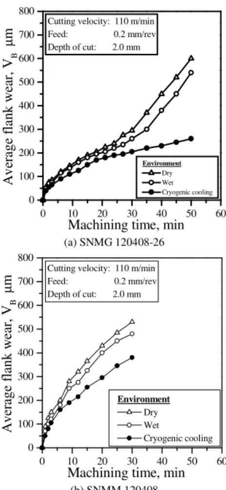
The growth of average flank wear, VB with machining time
observed while turning the steel rod by two different types of inserts at moderately high cutting velocity, feed and depth of cut under dry, wet and cryogenic environment have been shown in Fig.3. It is evident from Fig.3 that average flank wear, VB decreased
substantially by cryogenic cooling. Crater wear of carbide tools in machining steels particularly at higher Vc and f occur by adhesion
and diffusion as well as post abrasion, whereas, flank wear occurs mainly by micro-chipping and abrasion and with increase in Vc and
f adhesion and diffusion also come into picture due to intimate contact with the work surface at elevated temperature.
p r in c ip a l f l an k r ak e s u r fa c e s ec t io n A - A
n o tc h fl a n k w e a r
a u x il ar y fl an k
g ro o v in g w e a r c ra t e r
w e a r
VN
n o tc h
VM
A
VS M
A
VB
KT
KB
KM VS
Figure 2. Geometry and major features of wear of turning tools.
0 10 20 30 40 50 60
0 100 200 300 400 500 600 700 800
Environment
Dry Wet Cryogenic cooling
Cutting velocity: 110 m/min Feed: 0.2 mm/rev Depth of cut: 2.0 mm
A
v
er
ag
e
fl
an
k
w
ea
r,
V
B
µ
m
Machining time, min (a) SNMG 120408-26
0 10 20 30 40 50 60
0 100 200 300 400 500 600 700 800
Cutting velocity: 110 m/min Feed: 0.2 mm/rev Depth of cut: 2.0 mm
Environment
Dry Wet
Cryogenic cooling
A
v
er
ag
e
fl
an
k
w
ea
r,
V
B
µ
m
Machining time, min (b) SNMM 120408
Figure 3. Growth of average flank wear, VB with machining time under dry,
wet and cryogenic condition by (a) SNMG and (b) SNMM inserts.
The effect of dry, wet and cryogenic environments on growth of notch wear, VN observed during machining the steel by (a) SNMG
and (b) SNMM inserts at the same Vc-f-ap combination taken for the
tool wear tests have been shown in Fig.4. No significant notch wear was found to occur in any of the inserts. The growth of maximum flank (principal) wear, VM with time observed while turning the
steel by the inserts of two different configurations at a particular VC
-f-ap combination under dry, wet and cryogenic environments have
been shown in Fig.5.
0 10 20 30 40 50 60
0 100 200 300 400 500 600 700 800
Environment
Dry Wet
no notch wear under cryogenic cooling condition
Cutting velocity: 110 m/min Feed: 0.2 mm/rev Depth of cut: 2.0 mm
F
la
n
k
n
o
tc
h
w
ea
r,
V
N
µ
m
Machining time, min (a) SNMG 120408-26
Figure 4. Growth of flank notch wear, VN with machining time under dry,
0 10 20 30 40 50 60
0 100 200 300 400 500 600 700 800
Cutting velocity: 110 m/min Feed: 0.2 mm/rev Depth of cut: 2.0 mm
no notch wear under cryogenic cooling condition Environment Dry Wet F la n k n o tc h w ea r, V N µ m
Machining time, min (b) SNMM 120408
Figure 4. (Continued).
0 10 20 30 40 50 60
0 100 200 300 400 500 600 700 800 Environment Dry Wet Cryogenic cooling
Cutting velocity: 110 m/min Feed: 0.2 mm/rev Depth of cut: 2.0 mm
M ax im u m f la n k w ea r, V M µ m
Machining time, min (a) SNMG 120408-26
0 10 20 30 40 50 60
0 100 200 300 400 500 600 700 800
Cutting velocity: 110 m/min Feed: 0.2 mm/rev Depth of cut: 2.0 mm
Environment Dry Wet Cryogenic cooling M ax im u m f la n k w ea r, V M µ m
Machining time, min (b) SNMM 120408
Figure 5, Growth of maximum flank wear, VM with machining time under
dry, wet and cryogenic condition by (a) SNMG and (b) SNMM inserts.
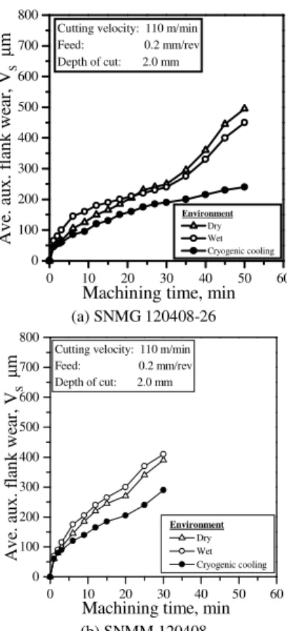
The auxiliary flank wears which affects dimensional accuracy and surface finish have also been recorded at regular intervals of machining under all the conditions undertaken. The growth of average auxiliary flank wear, VS with time of machining of the steel
under dry, wet and cryogenic conditions have been shown in Fig.6. Similarly, growth of maximum auxiliary flank wear, VSM recorded
with progress of machining has been shown in Fig.7.
0 10 20 30 40 50 60
0 100 200 300 400 500 600 700 800 Environment Dry Wet Cryogenic cooling Cutting velocity: 110 m/min
Feed: 0.2 mm/rev Depth of cut: 2.0 mm
A v e. a u x . fl an k w ea r, V S µ m
Machining time, min
(a) SNMG 120408-26
0 10 20 30 40 50 60
0 100 200 300 400 500 600 700 800
Cutting velocity: 110 m/min Feed: 0.2 mm/rev Depth of cut: 2.0 mm
Environment Dry Wet Cryogenic cooling A v e. a u x . fl an k w ea r, V S µ m
Machining time, min
(b) SNMM 120408
Figure 6. Growth of average auxiliary flank wear, VS with machining time
under dry, wet and cryogenic condition by (a) SNMG and (b) SNMM inserts.
0 10 20 30 40 50 60
0 100 200 300 400 500 600 700 800 Environment Dry Wet Cryogenic cooling
Cutting velocity: 110 m/min Feed: 0.2 mm/rev Depth of cut: 2.0 mm
M ax . au x . fl an k w ea r, V S M µ m
Machining time, min
(a) SNMG 120408-26
0 10 20 30 40 50 60
0 100 200 300 400 500 600 700 800
Cutting velocity: 110 m/min Feed: 0.2 mm/rev Depth of cut: 2.0 mm
Environment Dry Wet Cryogenic cooling M ax . au x . fl an k w ea r, V S M µ m
Machining time, min
(b) SNMM 120408
Figure 7. Growth of maximum auxiliary flank wear, VSM with time under
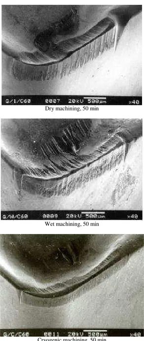
Dry machining, 50 min
Wet machining, 50 min
Cryogenic machining, 50 min
Figure 8. SEM views of worn out SNMG insert after machining under dry, wet and cryogenic conditions.
Dry machining, 30 min
Figure 9. SEM views of worn out SNMM insert after machining under dry, wet and cryogenic conditions.
Wet machining, 30 min
Cryogenic machining, 30 min
Figure 9. (Continued).
The pattern and extent of wear developed at the different surfaces of the tool tips after being used for machining the different steels over reasonably long period have been observed under SEM to see the actual effects of different environments on wear of the carbide inserts of present two configurations. The SEM views of the worn out SNMG insert after about 50 minutes of machining under dry, wet and cryogenic conditions have been shown in Fig.8. The SEM views of the worn out SNMM insert after about 30 minutes of machining under dry, wet and cryogenic conditions have been shown in Fig.9.
The SEM views of the worn out SNMG insert after machining steel at a particular Vc-f-ap combination under different
environments are shown in Fig.8 which clearly indicates that use of conventional cutting fluid did not significantly improve the nature and extent of wear, whereas application of liquid nitrogen has provided remarkable improvement and even after 50 minutes of machining, both flank and crater wear have been much uniform and much smaller in magnitude and without any notch wear. Only a small notch appeared on the auxiliary flank. In the process of systematic growth of cutting tool wear, the cutting tools usually first undergo rapid wear called break-in wear at the beginning of machining due to attrition and micro-chipping and then uniformly and relatively slow mechanical wear followed by faster wear at the end. Fig.9 shows that compared to the SNMG insert the SNMM type insert worn out much faster under both dry and cryogenic cooling conditions, which indicates that tool geometry plays substantial role on wearing of tool and also on the effectiveness of cryogenic cooling on control of tool wear. This difference might be due to straight and sharp cutting edges and large positive rake of the SNMM insert.
It is also evident from Fig.3 that usual flood cooling by soluble oil could reduce flank wear (VB) but not significantly in any of the
often surpasses the reduction of adhesion and diffusion wear of the carbide inserts expected due to cooling and lubrication by the cutting fluid in continuous machining like turning of steels (Dhar 2001).But application of cryogenic cooling by liquid nitrogen jets has substantially reduced growth of VB as can be seen in Fig.3. Such
improvement by liquid nitrogen jets can be attributed mainly to retention of hardness and sharpness of the cutting edge for their steady and intensive cooling, protection from oxidation and corrosion and absence of built-up edge (BUE) formation, which accelerates both crater and flank wear by flaking and chipping. Fig.3 also shows that VB increased much faster in case of SNMM insert
than in SNMG insert irrespective of the environments of machining. The possible reasons have already been mentioned. Fig.8, Fig.9 and Fig.4 show that while machining steel, both the inserts attained wide notching at their principal flank, which is caused mainly by abrasion and chemical action. Such flank notch wear, VN was totally absent
when liquid nitrogen was employed.
Fig.3 and Fig.5, when compared, also depict the maximum flank wear, VM has been all along slightly different from VB and this
difference is hardly visible in case of cryogenic cooling.
The auxiliary flank wear, which occurs due to rubbing of the tool tip against the finished surface, causes dimensional inaccuracy and worsens the surface finish. Gradual increase in depth of the auxiliary flank wear, which is proportional to the width of that wear, increases the diameter of the job in straight turning with the progress of machining. And the irregularity developed in the auxiliary cutting edge due to wear impairs the surface finish of the product.
Fig.8 shows that after machining the steel rod for 50 minutes under dry condition the SNMG insert attained sizeable wear with wide notch at the auxiliary flank. Wet machining under the same condition has not provided any significant improvement rather the notch has become much deeper expectedly for added chemical wear. Whereas, cryogenic application has resulted much lesser wear and notching as can be seen in the same figure. Fig.6 also shows that the value of average auxiliary flank wear, VS not only grew quite
rapidly but also got accelerated after about 30 minutes of machining by the SNMG insert under dry as well as wet condition. Application of liquid nitrogen jets, one of which is aligned towards the auxiliary kept the magnitude and rate of growth of VS all along much low.
The adverse and favourable effects of respectively wet and cryogenic machining on auxiliary flank wear of SNMM type insert are also evident in Fig.9 and Fig.6.
Unlike principal flank wear, auxiliary flank wear widely varies along the auxiliary flank reasonably for sharp variation in stresses and temperature and shallow but wide notching. Fig.7 shows that wet cutting aggravated the maximum auxiliary flank wear, VSM
vis-a-vis dry machining for both the inserts, whereas cryogenic cooling provided sizeable benefits.
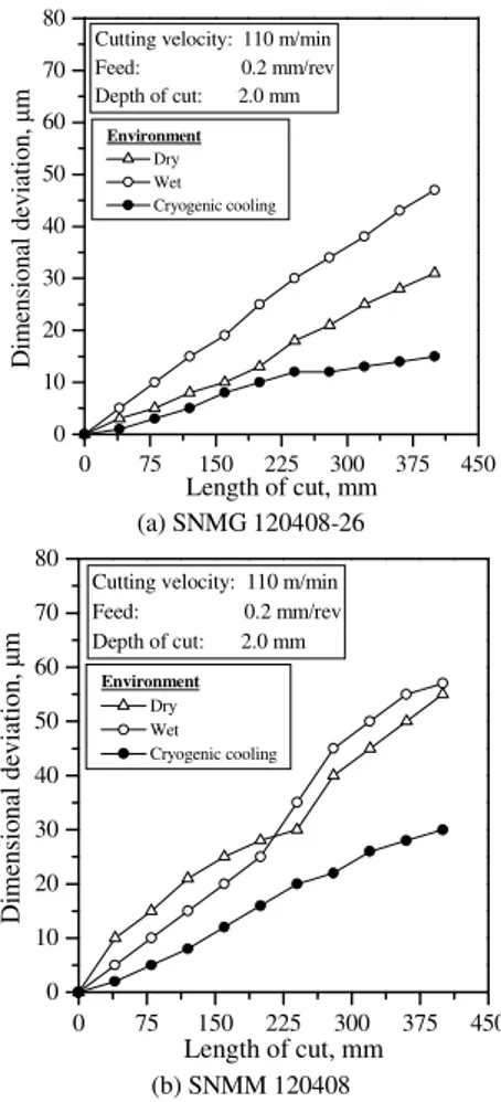
The quality of any machined product of given material is generally assessed by dimensional accuracy and surface integrity, which govern the performance and service life of that product. For the present study, only dimensional accuracy and surface finish have been considered for assessment of quality of product under dry, wet and cryogenic machining.
The variation in diameter of the job was precisely measured along its axis after one full pass of the machining over 400 mm length with full depth, at reasonably high feed and cutting velocity suitable for the tool-work combination. This has been done for all the tool-work-environment combinations undertaken keeping the initial diameter and length of the steel rods same and uniform as far as possible. The gradual increase in dimensional deviations on diameter observed along the length of cut on the steel rod after one full pass of machining at cutting velocity of 110 m/min, 2.0 mm depth of cut and 0.20 mm/rev feed under dry, wet and cryogenic cooling conditions have been shown in Fig.10.
0 75 150 225 300 375 450
0 10 20 30 40 50 60 70 80
Environment
Dry Wet Cryogenic cooling
Cutting velocity: 110 m/min Feed: 0.2 mm/rev Depth of cut: 2.0 mm
D
im
en
si
o
n
al
d
ev
ia
ti
o
n
,
µ
m
Length of cut, mm (a) SNMG 120408-26
0 75 150 225 300 375 450
0 10 20 30 40 50 60 70 80
Environment Dry Wet Cryogenic cooling
Cutting velocity: 110 m/min Feed: 0.2 mm/rev Depth of cut: 2.0 mm
D
im
en
si
o
n
al
d
ev
ia
ti
o
n
,
µ
m
Length of cut, mm
(b) SNMM 120408
Figure 10. Dimensional deviations observed after one full pass turning of the steel by (a) SNMG and (b) SNMM inserts under dry, wet and cryogenic conditions.
Fig.11 shows the variation in surface roughness with machining time for both the inserts under all the three environments. As cryogenic cooling by liquid nitrogen reduced average auxiliary flank wear and notch wear on auxiliary cutting edge, surface roughness also grew very slowly under cryogenic cooling. Conventionally applied cutting fluid did not reduce tool wear compared to dry machining. But the surface roughness deteriorated drastically under wet machining compared to dry, which may possible be attributed electrochemical interaction between insert and work piece.
0 10 20 30 40 50 60
2 3 4 5 6 7 8 9 10
Cutting velocity: 110 m/min Feed: 0.2 mm/rev Depth of cut: 2.0 mm
Environment
Dry Wet Cryogenic cooling
S
u
rf
ac
e
ro
u
g
h
n
es
s,
R
a
µ
m
Machining time, min
(a) SNMG 120408-26
0 10 20 30 40 50 60 2
3 4 5 6 7 8 9 10
Environment
Dry Wet Cryogenic cooling
Cutting velocity: 110 m/min Feed: 0.2 mm/rev Depth of cut: 2.0 mm
S
u
rf
ac
e
ro
u
g
h
n
es
s,
Ra
µ
m
Machining time, min
(b) SNMM 120408
Figure.11. (Continued).
Conclusions
The results of the experimental study presently carried out on tool wear in machining C-60 steel under different environments clearly depict that in machining steels, at least like C-60 steel, by carbide inserts, application of conventional method and type of cutting fluid like soluble oil does not help in reducing wear or improving tool life. But proper application of cryogen like liquid nitrogen in the form of jets provides substantial improvement. Such benefit of cryogenic cooling may be attributed mainly to reduction of abrasive and chemical wear at the tool flanks and also possible control of chip-tool interaction and thereby built-up edge formation which not only adds flaking wear but also accelerates chipping of the cutting edges by inducing vibration
Acknowledgement
This research work has been funded by Directorate of Advisory Extension and Research Services (DAERS), BUET, Dhaka, Bangladesh and also partially supported by the Department of Science and Technology (DST), Government of India. The authors are also grateful to the Department of Industrial and Production Engineering, BUET, Dhaka and Department of Mechanical Engineering, IIT, Kharagpur, India for providing the facilities to carryout the experiment. The help extended by the Principal, BCLT, Dhaka, Bangladesh for obtaining the scanning electron micrograph is also sincerely acknowledged.
References
Aronson, R. B., 1995, “Why Dry Machining”, Manufacturing
Engineering, Vol.114, pp.33-36.
Bennett, E.O., 1983, "Water Based Cutting Fluids and Human Health", Tribology Int.
Bennett, E. O and Bennett, D. L., 1985, “Occupational Airway Diseases in the Metal-working Industry”, Tribology Int., Vol. 18(3), pp.169-176.
Cassin, C. and Boothroyed, G., 1965, “Lubrication Action of Cutting Fluids”, J. Mech. Eng. Sci. Vol 7(1), pp. 67-81.
Chandrasekaran, H., Thuvander, A. and Johansson, J. O., 1998, “The Influence of Cutting Fluid on Tool Temperature Distribution in Single Point Turning of Steel”, 18th AIMTDR Conference, IIT Kharagpur, India, pp.219-224.
Chattopadhyay, A. B., Paul, S. and Dhar, N. R., 1999, “Fast Production Machining and Grinding Under Clean and Eco-friendly Environment”, Workshop on Clean Manuf., IEI, India, pp.21-24.
Chattopadhyay, A. K. and Chattopadhyay, A. B., 1982, “Wear and Performance of Coated Carbides and Ceramic Tools”, Wear, Vol.80, pp.239-253.
Dhar, N. R., Paul, S. and Chattopadhyay, A. B., 2000, “Improvement in Productivity and Quality in Machining Steels by Cryo Cooling”, Copen-2000, IIT, Madras, India, pp.247-255
Dhar, N. R., 2003, “Environmentally Reducing of Conventional Cutting Fluids in Metal Machining”, Journal of Mechanical Engineering, IEB, Bangladesh, Vol. ME 32, pp.94-107.
Dhar, N. R., 2001, “Effects of Cryogenic Cooling by Liquid Nitrogen Jets on Machinability of Steels”, Doctoral Dissertation, Dept. of Mech. Engg., IIT Kharagpur..
Ding, Y. and Hong, S. Y., 1998, “Improvement of Chip Breaking in Machining Low Carbon Steel by Cryogenically Precooling the Workpiece”, Trans. of ASME, Vol 120, pp. 76-83.
Ezugwu, E.O., Da Silva, R.B., Bonney, J. and Machado, A.R., 2005, ‘Evaluation of Performance of CBN Tools When Turning Ti-6Al-4V Alloy with High Pressure Coolant Supplies’, International Journal of Machine Tools and Manufacture, Vol. 45, pp. 1009-1014.
Hong, S. Qu, X. and Lee, A., 2001, “Economical Cryogenic Milling for Environmentally safe Manufacturing" Technical Papers of the North American Manufacturing Research Institute of SME at home page: http://www.columbia.edu/~ahl21/index2.html
Islam, S. 2005, “Effects of Cryogenic Cooling by Liquid Nitrogen Jet on Machinability of Steel by Coated Carbide Insert”, M. Sc. Engg. Dissertation, Department of Industrial & Production Engineering, BUET, Dhaka, Bangladesh
Kennedy, S.M., 1989, “Acute Pulmonary Responses Among Automobile Workings Exposed to Aerosols of Machining Fluids”, American J. of Industrial Medicine, Vol.15, pp.627-641.
Kitagawa, T., Kubo, A. and Maekawa, K., 1997, “Temperature and Wear of Cutting Tools in High Speed Machining of Inconel 718 and Ti-6V-2Sn”, Wear, Vol. 202, pp. 142-148.
Mazurkiewicz, M., Kubala, Z. and Chow, J., 1989, “Metal Machining with High-Pressure Water-Jet Cooling Assistance- A New Possibility”, J. Eng. Ind., Vol. 111, pp. 7-12.
Merchant, M. E., 1958, “The Physical Chemistry of Cutting Fluid Action”, Am. Chem. Soc., Preprint 3, No. 4A, pp. 179-189.
Nedess, C. and Hintze, W., 1989, “Characteristics Parameters of Chip Control in Turning Operations with Indexable Three Dimensionally Shaped
Chip Formers”, Annals of CIRP, Vol.38/1, pp.75-79.
Paul, S. and Chattopadhyay, A. B., 1995, “Effects of Cryogenic Cooling by Liquid Nitrogen Jet on Forces, Temperature and Surface Residual Stresses in Grinding”, Cryogenics, Vol.35, pp.515-523.
Paul, S. and Chattopadhyay, A. B., 1996a, “The Effect of Cryogenic Cooling on Grinding Forces”, Int. J. of Machine Tool and Manuf., Vol.36 (1), pp. 63-72.
Paul, S. and Chattopadhyay, A. B., 1996b, “Determination and Control of Grinding Zone Temperature under Cryogenic Cooling”, Int. J. of Machine Tool and Manuf., Vol.36(4), pp.491-501.
Peter, C. R., Steven, C. and David, L., 1996, “Evaporation of Polydisperse Multi Component Oil Droplets”, American Industrial Hygiene Association.
Reed, R. P. and Clark, A. F., 1983, “Materials at Low Temperatures”, American Society for Metals, Carnes Publication, Metal Park, OH.
Shaw, M. C., Pigott, J. D. and Richardson, L. P, 1951, “Effect of Cutting Fluid upon Chip-Tool Interface Temperature”, Trans. of ASME, Vol 71, pp. 45-56.
Singh, S. B., Chakraborty, A. K. and Chattopadhyay, A. B., 1997, “A Study of the Effects of Inclusion Contact on the Machinability and Wear Characteristics of 0.24% Carbon Steel”, Int. J. of Mat. Processing Tech., Vol.66, pp.90-96.
Thony, C., Thony, J. Lafontaine, M. and Limasset, J. C., 1975, “Occurrence of Polycyclic Aromatic Hydrocarbons in Some Cutting Oils- Study of the Corresponding Risk”, Arch. Mal. Prof. Med. Trav. Sec. Soc., Paris 36, pp.37-52.
Thoors, H and Chandrasekaran, H., 1994, “Influence of the Cutting Medium on Tool Wear during Turning”, Swedish Institute for Metal Research, Report No IM-3118.
Wang, Z. Y. and Rajurkar, K. P., 1997, “Wear of CBN Tool in Turning of Silicon Nitride With Cryogenic Cooling”, Int. J. of Mach. Tools and Manuf., Vol. 37, pp. 319-326.
Wang, Z. Y., Rajurkar, K. P. and Murugappan, M., 1996, “Cryogenic
PCBN Turning of Ceramic (Si3N4), Wear”, Vol. 195, pp. 1-6.