ISSN: 1549-3636
© 2014 Science Publications
doi:10.3844/jcssp.2014.508.520 Published Online 10 (3) 2014 (http://www.thescipub.com/jcs.toc)
Corresponding Author: Arivoli, A., Department of Information Science and Technology, Anna University, Chennai, Tamilnadu, India
C-LOAD POWER CONTROL PROTOCOL-CROSS-LAYER
DESIGN OF A NETWORK LAYER LOAD POWER CONTROL
PROTOCOL IN WIRELESS AD HOC NETWORKS
Arivoli, A. and P. Narayanasamy
Department of Information Science and Technology, Anna University, Chennai, Tamilnadu, India
Received 2013-08-01; Revised 2013-10-30; Accepted 2013-11-30
ABSTRACT
In wireless ad hoc network scenario, Cross-layer design is emerging, important in wireless ad hoc network and the power control methods. Power control is the intelligent selection of transmit power in a communication to achieve the better performance within the system. Cross-layer is used to sharing the information between the layers. Physical to Transport layer information are shared in this protocol, due to this cross-layering is designed to optimize the power control. CLD using LOADPOWER (LOADPOW) control protocol is reduce the overall end-end delay and the energy consumption using transmission power. The novelty of this work deals with both low and high transmission power control methodologies. So many power control schemes are dealt in MAC layer but this work, Power control protocol was done in network layer and it plays a vital role. A MAC approach to power control only does a local optimization whereas network layer is capable of global optimization. Simulation was done in NS-2 simulator with the performance metrics as improved throughput, energy consumption and end-end delay. The key concept is to improve the throughput, saves energy by sending all the packets with optimal transmission power according to the network load. A comparison of few protocols with Load Power Control Protocol (LPCP) was implemented and got the better performances using NS-2 simulator.
Keywords: CLD, MAC, LOADPOWER, LPCP
1. INTRODUCTION
An ad hoc network is a set of nodes that have the ability to communicate wirelessly without the existence of any fixed infrastructure. Nodes in an ad hoc network use other nodes as intermediate relays to transmit packets to their destinations. Since nodes are usually battery operated, energy conservation is an important issue. Furthermore, because of the broadcast nature of the wireless medium, ad hoc networks are also limited by interference/capacity considerations. CLD is used to sharing the information between the layers. The network is ad hoc because it does not rely on a preexisting infrastructure, such as routers in wired networks or access points in managed (infrastructure) wireless networks. Instead, each node participates in routing by forwarding data for other nodes and so the determination
of which nodes forward data is made dynamically based on the network connectivity. Some of the challenges involved in the creation of an ad hoc network are:
• Routing challenges: Routing in a dynamically changing environment
• Wireless medium challenges: Lower bandwidth, higher error rates, frequent disconnections and less security compared to fiber carriers
• Portability challenges: Lower power and smaller storage capacity compared to desktop computers
1.1. Power Control
layer. Arivoli and Narayanasamy (2013) stated that power control used by asymmetric routes by sending back AODV route-replies along the route the route-request traversed through the source and destination.
Challenging in ad hoc wireless networks. Further, if the ad hoc network is large consisting of thousands of nodes, collecting information from all the nodes and passing it to the concerned nodes lead to high overheads. Thus, distributed topology control algorithms that are asynchronous, scalable and localized are particularly attractive for ad hoc networks. The power control in ad hoc networks determines the quality of Physical layer link. MAC layer bandwidth and degree of spatial reuse, while at the same time affects the network layer routing, transport layer congestion control and QOS of application layer.
Tan and Bose (2005) reported that modifying in AODV routing protocol results in energy consumption in the wireless channel. An ad hoc network typically refers to any set of networks where all devices have equal status on a network and are free to associate with any other ad hoc network devices in link range. Very often, ad hoc network refers to a mode of operation of IEEE 802.11 wireless networks. Gomez et al. (2003) found that PARO consumed less power in order to find power-efficient routes Power management in ad hoc networks is a more difficult problem for two reasons. First, in ad hoc networks, a node can be both a data source/sink and a router that forwards data for other nodes and participates in high-level routing and control protocols. Lee et al. (2005) consider both the power-aware routing algorithm and also a MAC layer algorithm that is adequate to optimize its performance in broadcasting. Narayanaswamy et al. (2002) stated that COMPOW protocol in wireless ad hoc networks assumes common power level for all the routes in the network using the
shown that LEAR achieves balanced energy consumption based only on local information, thus removes the blocking property of other energy-aware routing algorithms proposed elsewhere. A wireless node in an ad-hoc network has limited battery power supplies. Therefore, it is important to reduce its energy consumption. A wireless node has four modes: Transmit, receive, idle and doze.
1.2. Cross-Layer Design Definition
To fully optimize wireless broadband networks both the challenging from the physical medium and the QoS-demands from the applications have to be taken into account. Rate, power and coding at the physical layer can be adapted to meet the requirements of the application given the current channel and network conditions. Knowledge has to be shared between all layers to obtain the highest possibly adaptively. Li et al. (2008; 2009) proved that cross-layer design for AODV routing protocol used to minimize the energy consumption in power control routing.
Cross-Layer Design (CLD) is a new paradigm for network architecture that allows making better use of network resources by optimizing across the boundaries of traditional network layers. This proposed Cross-layer with LOADPOWER control protocol improves the network lifetime along with the total-energy consumption.
1.3. Motivations for Cross- Layer Design
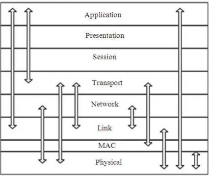
Fig. 1. Creation of cross-layer design
In “Fig. 1”, Cross-layer or interlayer networking can be considered as one in which different layers of the network protocol stack inter-communicate the useful information so as to collectively achieve the desired vertical optimization goal. For the sake of Quality of Service (QoS) requirements varying with applications, the network or higher layers function should directly base on the information from the lower physical and MAC layers.
Steps:
• First the new interfaces are created in the protocol stack
• Merging of these layers is done • Merged layers are designed in the stack
• Inter-layer communication takes place using the shared information in the protocol stack
Design:
• There exists the direct coupling between the physical and the upper layer
• In Cross-layer design, only to meet the fast growing demands
• Cross-layer design required to integrate all the layers
Cross-layer design is not a non-layered or single-layered design.
1.4. Necessity for Cross-Layer
System energy consumption is affected by all layers. On the other hand, all layers should co-operate to reduce overall system energy consumption. Cross-layer design is a way to make such co-operation possible.
In “Fig. 2”, it blurs the line between layers and leads the optimization of cross layer functionalities. Currently ad hoc routing protocols work mainly on the network
layer. It guarantees the independency of the network layer. However each layer needs to do redundant processing and unnecessary packet exchange to get information that is easily available to other layers. This increases control signals resulting in wastage of bandwidth, packet collision. By using interlayer interaction, different layers can share locally available information. This will result in substantial amount of performance improvement. In Fig. 2 shows the possible interaction between the cross-layer designs.
In this study chapter 2 deals with the MTPR and MINPOW protocol power control. The chapter 3 LOADPOWER control protocol shows the minimum power control with lower end-end delay. Implementation was done in NS-2 simulator.
2. MATERIALS AND METHODS
2.1. Minimum
Total
Transmission
Power
Routing (MTPR)
It uses a simple energy metric representing the total energy consumed along a route. Formally, consider a generic route Rd = N0, N1,…,Nd, where N0 is the source
node, Nd is the destination node and T(Ni , Nj) denotes
the energy consumed when transmitting over the hop (Ni,
Nj), the total transmission power P of the route Rd is
calculated as per Equation (1):
d 1
i i 1 i 0
P(Rd) T(N , N )
−
+ =
=
∑
(1)The optimal route Ro must have the minimum total
transmission power as per Equation (2):
*
o i
RjЄR
Fig. 2. Cross-layer design (Possible inter-layer communication)
where, R* is the set of all possible routes. Although MTPR can reduce the total transmission power consumed per packet. Chang and Tassiulas (2000) explained the energy conservation for routing protocols. In order to maximize the network lifetime, we need to maximize the minimum lifetime for all nodes in the network. Furthermore, we need to consider the flow conservation separately applied to each commodity.
2.2. MINPOW PROTOCOL
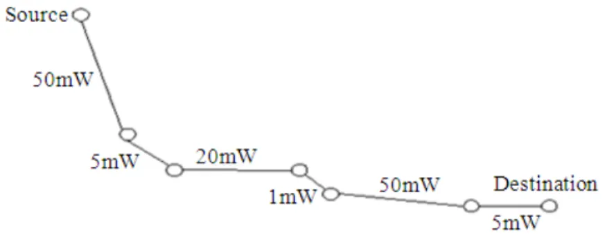
Energy consumption is however also an important metrics, the network capacity and energy consumption are not optimized simultaneously for current off the-shelf wireless cards. It proactively sends the transmit power levels available, all of them containing the same sequence number of the corresponding minimum power level. Three components PTxelec and PRxelec are known locally to the transmitter and receiver respectively, while PTxRad (p) can be calculated if the smallest transmit power Pi required to traverse a link l can be estimated. Each node takes its own power leveling “Fig. 3”.
2.3. Properties
• It provides a globally optimal solution with respect to total power consumption. This may not be the optimal solution for network capacity; the two objectives are not simultaneously satisfiable
• MINPOW provides loop free routes. This is true because the distributed Bellman-Ford algorithm with sequence numbers is loop free for non-negative link cost
• No location information or measurement support from the physical layer is needed
• The architecture works for both proactive, as well as Reactive routing protocols
In this MINPOW protocol each node chooses the power level. So the power control is reduced when the each node choosing its own power level.
2.4. Proposed Work
Fig. 3. MINPOW diagram
LOADPOW power control protocol which adapts the transmit power according to the network load. It opportunistically uses a higher transmit power level whenever the network load is low and lowers the transmit power as the load increases. The LOADPOW algorithm attempts to avoid interference with ongoing traffic by making each node refrain from using a transmit power that would interfere with an ongoing communication in the neighborhood.
2.5. Load Power Control Architecture
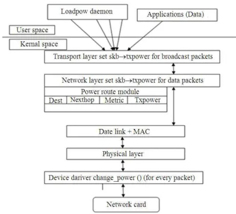
According to “Fig. 4”, The Load power domain is running in the network layer. Each node in the network find out the individual power level, when the transmission takes place, each node assigns its individual power according to the network traffic. The transmission power is set for the data packets and the power level is changed for every individual packet in the network. In the network layer, the power route module consists of DEST, NEXTHOP, METRIC and TXPOWER. In this Cross-layer deals with physical to transport layer. All the information’s are shared between these four layers. LOADPOWER agent runs the routing domain from RS to Rd. Transport layer set the TXpower
to broadcast the packets. It reduces the overall end-end delay and increase the network lifetime.
The Software architecture diagram of LOADPOWER architecture shows that the network layer power control has a impact on POWERROUTE. The source node should send the source id and the Power Level (PLi) to
the neighboring nodes in the network. When the power level is assigns to all nodes in the network and then it starts the routing. In this LOADPOWER architecture, only the energy efficient nodes only taken into consideration for routing. Transmission power is high, when compared to the received power in the overall
network. Performance parameters for LOADPOW protocol is mainly end-end delay, throughput and the energy consumption.
2.6. Asymmetric Routes
Although advanced routing schemes such as ODMRP, WRP could potentially be used to use symmetric routes, such mechanisms are not considered in this work. For our simulations, restrict the route selection process to choose only asymmetric routes by sending back AODV route-replies along the route the route-request traversed through the source and destination.
2.7. Network Load
Network load is defined as that, how many nodes that are currently available in the network. Based on that network load is calculated. Due to mobility, nodes move with random. According to that network load could be calculated.
Because this is an unmanaged, decentralized system:
• Devices are not distributed across the space evenly • No one device can be guaranteed to hear all other
devices
• No one device can be trusted to calculate fairly for all devices
• All devices must calculate load for their particular space and situation
Fig. 4. Load power architecture
2.8. Calculation of Energy Efficiency in the
Network
Calculating the network load depending upon the size of the network. When the nodes in the network changes, according to the network load transmission power could be changed. In the network, which nodes having more battery life, TTL value. Those nodes are taken as energy efficiency nodes.
2.9.
Network Load is High; Low Transmission
Power Gives Higher End-End Delay
LOADPOW domain is running with the two different scenarios, first case is, when the network load is high; the low transmission gives high end-end delay. Assume, if there are 10 nodes in the network environment. Initially 300 mw power is given as the transmission power then the initial node starts to transmit the power to all the nodes surrounded in the region using the routing protocol. The node selects the path according to the routing and distributes the low power to all the nodes, so delay is increased.
2.10. Network Load is Low; High Transmission
Power Gives Lower End-End Delay
According to this network, the high transmission power gives lower end-end delay. When the transmission starts at the node, the source node starts distributing the transmission power to the neighboring nodes and higher power is transmitted using asymmetric link communications. Delay is reduced and energy consumption is also minimized.
2.11. Network Load
Network Load is defined as that, how many nodes that are currently available in the network. Based on that network load is calculated. Due to mobility, nodes move with random. According to that network load could be calculated.
Because this is an unmanaged, decentralized system:
• Devices are not distributed across the space evenly • No one device can be guaranteed to hear all other
devices
• All devices must calculate load for their particular space and situation
This protocols deal with two scenarios, when the network load is high, lower transmission power gives lower end-end delay. When the network load is low, higher transmission power gives higher end-end delay. The transmission takes place only the nodes having more energy efficiency. So the transmitted power is low, when compared with the received power in the network.
2.12. Calculation of Energy Efficiency in the
Network
Calculating the network load depending upon the size of the network. When the nodes in the network changes, according to the network load transmission power could be changed. In the network, which nodes having more battery life, TTL value. Those nodes are taken as energy efficiency nodes.
2.12.1. Example
Consider the network with the total number of 10 nodes:
• Calculate total transmission power according to the total network size
• Energy efficiency nodes are find out
• Finding the energy efficiency node in the overall network
• Transmission power can be transmitted only in the energy efficient nodes
• Among the 10nodes only 4 nodes are participated in the communication
3. RESULTS AND DISCUSSION
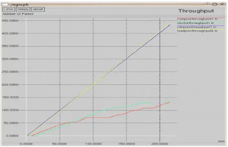
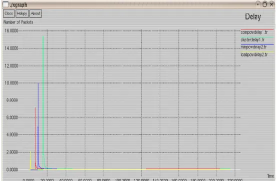
The simulation of the LOADPOW Protocol is based on the network load. When the load is low, high transmission is to be given. Initializing 20 nodes in the network and the communications take place between the nodes. First finding the nodes having the energy efficiency. Energy efficiency is that the power levels lies between 4mw-5mw then it chooses the nodes. When the nodes does not having the energy efficiency it drops the packet and chooses another node for communication. Our goal is to reduce the end-to-end delay, increase the throughput and minimizes the energy. In X-graph COMPOW Protocol is indicated by Red color, CLUSTERPOW Protocol is indicated by Green color, MINPOW Protocol is indicated by Blue color and the LOADPOW Protocol is indicated by yellow color.
Asymmetric routing occurs when the path from node n1 to node n2 is different from the path from n2 to n1. The following shows a simple topology and cost configuration that can achieve such a result: Nodes n1 and n2 use different paths to reach each other. All other pairs of nodes use symmetric paths to reach each other:
$ns cost $n1 $r1 2 $ns cost $n2 $r2 2 $ns cost $r1 $n2 3
Any routing protocol that uses link costs as the metric can observe such asymmetric routing if the link costs are appropriately configured.
Table 1 shows the parameters and the settings for the simulation environment in ns-2 simulator. Parameters are channel type, radio propogation model, antenna type and so on. In this simulator 20 nodes are participating and AODV routing protocol are used for routing for LOADPOW protocol.
3.1. Comparison of Throughput for Four
Protocols
A measure of the amount of data transferred in a specific amount of time, usually expressed as bits per second (bps) is called as throughput. The amount of data moved successfully from one place to another in a given time period.
3.2. Effect of Time and Number of Packets
Fig. 5. Throughputs for four protocols Table 1. Simulation parameters
Parameters settings
Channel type Channel/Wireless channel Radio-propagation model Propagation/TwoRayGround Antenna type Antenna/Omni antenna Link layer type LL
Interface queue type Queue/DropTail/PriQueue Max packet in ifq 250
Network interface type Phy/WirelessPhy MAC type Mac/802_11 Number of mobile nodes 20
Routing protocol AODV Battery model Battery/Simple Generic radio hardware Radio/Simple
3.3. Comparison of Delay for Four Protocols
The amount of actual user data transmitted per second without the overhead of protocol information such as start/stop bits or frame headers and trailers is called as delay.
3.4. Effect of Time and Number of Packets
According to the “Fig. 6”, a delay varies for all protocols in which LOADPOW Protocol reduces the end-to-end delay. LOADPOW protocol initializes the transmission power based on the network load. Transmission takes place only the energy efficient nodes. So, the nodes having higher energy efficiency take part in transmission and reduce the delay. The COMPOW, CLUSTERPOW, MINPOW Protocols having higher end-to-end delay due to the network capacity. Delay reduces based on the network and the traffic carrying
capacity. In LOADPOW it maintains the traffic so the delay is reduced. At 20-200 sec delay is saturated at particular time 0 sec in LOADPOW. Other protocols increasing the delay with respect to number of packets in the network.
3.5. Comparison of Power Consumption for
Four Protocols
Power Consumption is defined as that amount of power consumed by the nodes during transmission. It is denoted by mw.
3.6. Effect of Time and Power
Fig. 6. Delays for four protocols
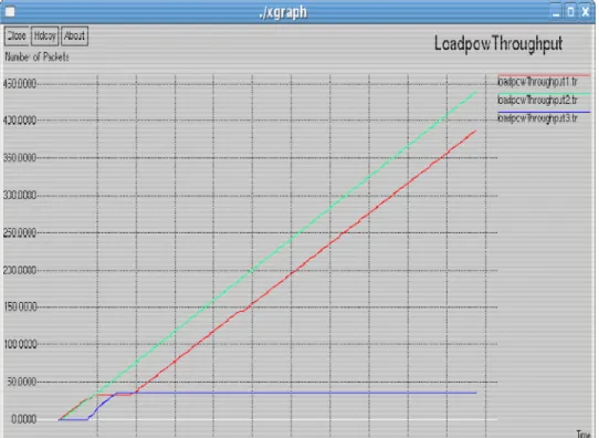
Fig. 8. LOADPOW Throughput
3.7. Throughput,
Delay
for
LOADPOW
Protocol LOADPOW Throughput-Time
(Vs) Number of Packets
In “Fig. 8”, LOADPOW Protocol throughput for varies for source and destination. In our simulation, considering 3 sources and destination. Based on the source and destination throughput differs in throughput. First and source and destination increases the throughput based on transmission power and Asymmetric routes. But the final source and destination decreases the throughput due to lower transmission power. But the overall throughput is increasing in LOADPOW Protocol.
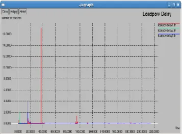
3.8. LOADPOW Delay-Time (Vs) Number of
Packets
In “Fig. 9”, LOADPOW Delay considering 3 sources and destinations. Delay varies for various source and destination. Delay varies according to transmission power. In LOADPOW it uses the independent power, but first source and destination increases the delay and the second and third decreases the delay. So the overall delay is reduces the end to end delay in the network.
3.9. Simulation Environment
In “Fig. 10”, shows LOADPOW power control protocol simulation based on the network load, transmission power is to be given. When the network load is low, high transmission power is given. It distributes the transmission power to all the nodes. Each node selects its own power level because it is asymmetric routes. In our simulation, we used 20 nodes for the transmission. The power level is denoted by mw (milli watts). Less mw is taken for the overall transmission to reduce the power level. So the nodes selects the very low power level according to the packet size.
Fig. 9. LOADPOW Delay
Fig. 10. Simulation of transmission power
Fig. 13. Communicated nodes
In “Fig. 12”, asymmetric routes are communicated in LOADPOW. Independent power control algorithm is used for transmission. When the node is not energy efficiency it selects the other node for communication. 15 is the source and 14 is the destination. Three source and destination are given in LOADPOW protocol. By considering energy efficiency, it reduces the end to end delay, increases the throughput and minimizes the energy consumption. The higher transmission power is given during transmission and lower power is received at the receiver. So LOADPOW power control protocol is reduces the power level efficiently than the other three protocols.
In “Fig. 13”, all the energy efficient nodes are communicated and the powers also distributed. The nodes having more threshold value only take part in the communication. The simulation setup may be vary according to the routing protocols. In this simulation
LOADPOW used AODV routing and all other power control method uses the different routing protocol. In MINPOW, DSDV routing protocol is used.
4. CONCLUSION
Power control is a prototypical example of a cross-layer design problem. We identified the impact of power control on a variety of parameters and phenomenon and then presented fundamental design principles. We then developed protocols guided by these principles, taking into account architectural considerations for implementing them in an actual system. Some of the protocols have been implemented and tested been implemented and tested. Perhaps, the holistic approach used here may be useful in other such context.
consumption. Depends on protocols the power control is to be reduced. The main consideration is the performance metrics like throughput, delay and energy consumption. Power control is often considered a problem belonging completely at the MAC layer, thus MAC protocols dealing with power control have been proposed. Implementing power control in MAC layer is tedious. In future work MAC layers plays main role in the power control protocols. MAC layer in power control plays a local optimization but network layer plays a global optimization. But MAC layer power is a symmetric in nature. Changing of power is difficult in MAC layer.
5.
A
CKNOWLEDGMENT
This work was supported by UGC (BSR) research grants by New Delhi.
6. REFERENCES
Arivoli, A. and P. Narayanasamy, 2013. Cross-layer design of an asymmetric load power in ad hoc networks. Int. J. Inform. Technol.
Chang, J.H. and L. Tassiulas, 2000. Energy conserving routing in wireless ad-hoc networks. Proceedings of the IEEE 19th Annual Joint Conference of the IEEE Computer and Communications Societies, IEEE Xplore Press, Tel Aviv, pp: 22-31. DOI: 10.1109/INFCOM.2000.832170
Gomez, J., A.T. Campbell, M. Naghshineh and C. Bisdikian, 2003. PARO: Supporting dynamic power controlled routing in wireless ad hoc networks. Wireless Netw., 9: 443-460. DOI: 10.1023/A:1024636132348
Kawadia, V. and P.R. Kumar, 2005. Principles and protocols for power control in wireless ad hoc networks. IEEE J. Select Areas Commun., 23: 76-88. DOI: 10.1109/JSAC.2004.837354(410) 23 Lee, S.H., E. Choi and D.H. Cho, 2005. Timer-based
broadcasting for aware routing in power-controlled wireless ad hoc networks. IEEE
Commun. Lett., 9: 222-224. DOI:
10.1109/LCOMM.2005.03008
Li, B., Z. Jin and Y. Shu, 2009. Cross-layer design of energy-saving AODV routing protocol. Trans. Tianjin Univ., 15: 343-349. DOI: 10.1007/s12209-009-0060-z
Li, B., Z. Jin, X. Zhong, Y. Sun and Y. Shu, 2008. CEMAODV: Cross-layer design of energy-conserving multicast AODV routing protocol. Proceedings of the 3rd International Conference on Communications and Networking in China, Aug. 25-27, IEEE Xplore Press, Hangzhou, pp: 743-747. DOI: 10.1109/CHINACOM.2008.4685130
Narayanaswamy, S., V. Kawadia, R.S. Sreenivas and P. R. Kumar, 2002. Power control in ad hoc networks theory, architecture, algorithm and implementation of the COMPOW protocol. Proceedings of the European Wireless Conference, (EWC’ 02), Florence, pp: 156-162.
Park, S.J. and R. Sivakumar, 2002. Load-sensitive transmission power control in wireless ad-hoc networks. Proceedings of IEEE Global Telecommunications Conference, Nov. 17-21, IEEE
Xplore Press, pp: 42-46. DOI:
10.1109/GLOCOM.2002.1188038
Singh, V.P. and K. Kumar, 2011. Literature survey on power control algorithms for mobile ad-hoc network. Wireless Personal Commun., 60: 679-685. DOI: 10.1007/s11277-010-9967-x
Tan, C.W. and S.K. Bose, 2005. Modifying AODV for efficient power-aware routing in MANETs. Proceedings of the IEEE Region TENCON, Nov. 21-24, IEEE Xplore Press, Melbourne, Qld., pp: 1-6. DOI: 10.1109/TENCON.2005.300970