Analysis of Electrical Circuits with
Controlled Sources through the Principle of
Superposition
#1
T. S. Rathore, #2Jayasudha Koti and *3Sunita R. Sharma
#Department of Electronics & Telecommunication Engineering,
St Francis Institute of Technology, Mt Poinsur, S. V. P. Road, Borivali (W), Mumbai 400 103, India.
1
tsrathor@ee.iitb.ac.in
2
jayasudhakoti@yahoo.co.in
*Sunita R. Sharma
Department of Electronics & Telecommunication
Watumull Institute of Electronics Engineering & Computer Technology, Worli, Mumbai, India.
3
atinusharma@yahoo.com
Abstract— In the text books, while solving the circuits with controlled sources using Principle of Superposition (POS), controlled sources are not deactivated. Thus POS has not been applied in the ‘true sense’ to circuits with dependent sources. It is shown here that POS can be applied in the ‘true sense’ to such circuits also, but with caution. POS is applicable to all those circuits with dependent sources as well, if it is applicable to these circuits when all the dependent sources are treated as independent sources. We have included two such examples: one which cannot be solved only employing series-parallel reduction, current voltage division, and Ohm’s law, second which has more than one controlled sources. The method based on POS is compared with that based on Miller equivalents and generalized matrix method. It is shown that the latter one is the most efficient. It is hoped that the teachers will emphasize that POS can be applied, in the true sense, for analysing circuits with controlled sources. The prospective authors would include this theory in their future text books. However, they should motivate the students to use generalized matrix method for better efficiency.
Keyword-Circuit analysis, controlled sources, matrix method, Miller theorem, superposition
I. INTRODUCTION
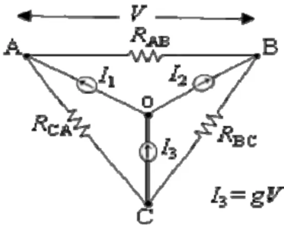
S many as 20 introductory books on circuit analysis [1-20] have been referred to by Leach [21] in order to find out if dependent sources can be suppressed while applying the principle of superposition (POS) to electrical circuits. He finds that these books either state or imply that superposition of dependent sources is not allowed, which, he contends, is a misconception. He finally concludes that POS can be applied to such networks also through a formal proof followed by several examples. Unfortunately, the reviewer of his paper [21] cited a circuit shown in Fig. 1 where the POS cannot be applied. Leach [21] mentions that the circuit cannot be solved by any other method. This will be shown in this paper.
Fig. 1. A circuit not solvable by POS.
The conditions where POS cannot be applied are stated in [21]. In this paper, we give a general condition on the circuits to which POS cannot be applied.
Damper [22] feels there is an error in Leach’s proof [21] but agrees to his final conclusion. Without involving Leach’s proof and Damper’s subsequent correction, we provide a simple, but convincing proof. The results are verified by the matrix method [23].
All the examples in [21] are solved by employing voltage and current division, series-parallel reduction, and Ohm’s law. In this paper, it is shown through an example that there are circuits which cannot be solved just by using these techniques. One needs to use star/delta transformation, KCL, KVL, or more general matrix method [23]. Also we have taken one example which has two controlled sources. Finally, we show that the matrix method is more efficient.
II. ANALYSIS OF CIRCUITS WITH CONTROLLED SOURCES USING POS
We prove that POS can be applied in ‘true sense’ in solving the circuits with controlled sources. Here ‘true sense’ means that the response due to all the independent and dependent sources is obtained by superimposing the responses obtained, considering one source at a time. For convenience, without any loss of generality, we take the typical two-node network shown in Fig. 2, with current sources only as it is explained in [21] that voltage sources, if present, can be converted into current sources. Using node analysis, one can write
Fig. 2. Typical 2 node network.
. 22
12 12 11
x kV I
I
Iy x I
Vy x V
y y
y y
(1)
Note that
I
x and
I
ymay or may not contain the independent and/or dependent sources depending upon the position of the current sources in the circuit. In the circuit shown, node X has the independent current source I only while node Y has both the independent current source I and dependent current source KVx. Eqn (1) can be rewritten as(2)
where Ri is the response due to the independent source I and Rd is that due to the dependent source kVx. It is obvious from eqn (2) that the node voltages can be solved by the POS. For example
Vx = Vx1 + Vx2
22 12 0
22 12
y x kV
y y
I y I
x
V (3)
0
22 12
12 11
d R i R
x kV I I Vy
x V y y
y y
where Δ = y11y22 - y122.
Here dependent source kVx should be treated as an independent source of value kVx where Vx is the full and final value, i.e., when all the sources (independent and dependent) are present. Hence, it can be deactivated without reducing the controlling variable Vx to zero while determining the response due to the independent source I, like we do not put any current through, or voltage across, any element 0 while deactivating an independent source.
Solving for Vxfrom (3), one gets
I k y y y x V 12 ) 12 22 ( (4)
Similarly, from eqn (2), by Cramer’s rule, one gets
. 11 12 11 12 0 11 12 11 x kV y I y y x kV y y I y I y y V
Substituting for Vx from (4), and simplifying
. 12 ) 12 11 ( I k y k y y y V (5)
Now we solve the circuit by the matrix method of [23]. Equation (1) can be expressed as
Vy x V k I I Vy x V y y y y 0 0 0 . 22 12 12 11 which yields . 22 12 12 11
I I Vy x V y k y y yOn solving one gets
I k y y y x V 12 ) 12 22 ( (6) and I k y k y y y V 12 ) 12 11 ( (7)
Equations (6) and (7) are the same as eqns (4) and (5), respectively. Thus, we conclude that POS can be applied to linear circuits with controlled sources also.
and the voltage source is shorted, respectively. The circuit in Fig. 1 is solvable when one of the current sources, say I3 is a dependent source such that I3 = I1 + I2 (requirement of KCL).If we further make that I3 = gV [21], the
circuit becomes unsolvable because two constraints on I3 cannot simultaneously be satisfied. Similarly, the
circuit shown in Fig. 3 is solvable when one of the voltage sources, say VCA, is a dependent source such that VCA
= -(VAB + VBC) (requirement of KVL), but becomes unsolvable when VCA is also dependent on some other
voltage or current in the circuit.
Fig. 3. A circuit to which POS cannot be applied.
Example 1: Determine the output voltage Vo in the circuit shown in Fig. 4 [22].
Fig. 4: Circuit for Example 1.
Applying POS
Vo = V1 (due to the source Vs alone) + V2 (due to the source AVs alone) = 0 + AVs =AVs.
Example 2: Find the current through G2 in Fig. 2 when G1 = 0.8 S, G2 = 0.2 S, G3 = 0.3 S, k = 0.8 S, I = 23 A.
Applying POS
2
Gb G3
G1b G x kV G G a G
a G I x V
where
2 1
2 1
, 3 1
3 1
G G
G G b G G G
G G a G
Substituting the values, one gets
V. 23 ) 23 / 8 (
15
Vx Vx
x V
By POS for Vy
. 0 40 40 )
23 / 40 ( 40
3 3
2
1
x V
G b G x kV G G a G
a G I
Vy
Example 3: Determine current I in the circuit shown in Fig. 5.
Fig. 5. Circuit for Example 3. By POS,
A. 6 . 4
) 23 / 32 ( 11
3 4
2 23
I I
G b G
b G I G a G
a G I
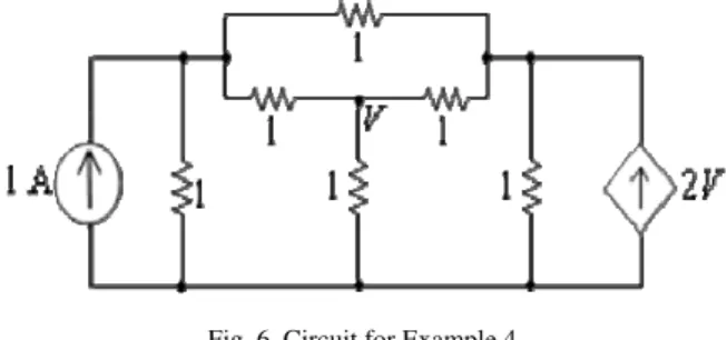
Example 4: Consider the circuit shown in Fig. 6.
Fig. 6. Circuit for Example 4.
This circuit cannot be solved by series-parallel reduction, current and voltage division and Ohm’s law. We solve it by matrix method [23].
By POS and using node analysis, one gets
V V
V
2 1
4 1
3 1 1
1 3 1
1 1 3
3 2 1
1 0 1
1 0 3
3 1 1
1 3 1
1 1 3
3 0 1
1 0 1
1 1 3
V. 2 1
V
This is the correct answer verified by other method.
If a network does not have a single independent source, but has dependent sources only, then from eqn (2), we see that Ri= 0 and consequently, Rd will also be zero. It means that, in the absence of any independent source, the circuit is dead, i.e., no current through, and voltage across, any element exist, even though the dependent source(s) may be present.
While determining Thevenin equivalent of a circuit without any independent source but with dependent source, both the open circuit voltage and the short circuit current will be zero as explained above. In such a case, Thevenin resistance would be indeterminate using the relation Rth = Voc/Isc =0/0. However, if we connect an
Example 5: Find the Thevenin equivalent of the circuit across the terminals AB shown in Fig. 7.
(a)
(b)
Fig. 7. (a) Circuit for Example 5 and (b) External voltage source connected. We connect a voltage source at the terminals AB. By POS
. 4
2 2
1
R Th R I V I R R
R V R
I
Example 6: Determine the node voltages Va and Vb in the circuit shown in Fig. 8(a).
There are two dependent sources; one is controlled by a voltage Vo and the other by current Io which require the evaluation of corresponding difference of two node voltages. Such controlling variables almost double the complexity of the solution by POS. Such a problem has not been considered in [21-22].
(a)
(b)
Fig. 8. (a) Circuit for Example 6 and (b) reduced circuit.
2 1
1 3
2 3
1 0
2 1
1 3
2 0
1 2
2 1
1 3
2 0
1 12
Vo
o I
a V
5 3 4 24
Io Vo (8)
5 9 2
12 Io Vo
(9)
/1
Now
Io VaVb (10)
(11)
a V o
V 12
Now (12)
(13)
From eqns (11) and (13), by Cramer’s rule
A. 8
2 1
1 2
18 1
4 2
V, 2
2 1
1 2
2 18
1 4
Io
o
V
Substituting the values of Vo and Ioin eqns (8) and (9) one gets
.
V 2 , V10
Vb
a
V
Now let us solve the same problem by Matrix method [23]. Node analysis gives
2 1
1 3
3 1
0 3
2 1
1 3
0 1
2 3
2 1
1 3
0 1
12 3
Vo
o I
b V
5 9 2 12
5 3 4 24
Io Vo Io Vo
4
2
Vo Io
5 3 4 24
12 Io Vo
18
2
36 12 2 4 1 1 0 3 2 2 36 12 3 36 2 2 12 ) 12 ( 3 ) ( 2 12 3 2 12 2 1 1 3b V a V b V a V a V b V a V a V b V a V o V o I b V a V
By Cramer’s rule
V 2 2 4 1 1 36 4 12 1 , V 10 2 4 1 1 2 36 1 12
Vb
a
V
These are the same as obtained above, but with considerably less effort in solving.
III. COMPARISON WITH OTHER METHODS
There is a similarity between the methods based on POS and Miller equivalents [25]. In the former method, the sources are dependent while in the latter method, the elements are dependent on some parameter. However, in both the methods, one has to determine the controlling variables first and then any other desired voltage or current. As proved in [23], matrix method is more efficient than the Miller equivalent approach. It is also more efficient than the method based on POS. This is proved below.
Let there be N number of unknown nodes and Si and Sd be the number of independent and dependent sources, respectively, in a circuit. We shall compare the number of determinants to be solved by the POS method and the matrix method for determining the voltages of N nodes. In POS method, N equations for N node voltages in terms of controlling variables are to be written invoking POS. These relations require N(Si + Sd) + 1 determinants of the order
N
N
to be solved. After this Sd relations among the controlling variables will be determined. Then evaluation of the controlling variables from these relations requires Sd +1 determinants of order Sd
Sd to be solved. After this the voltages of N unknown nodes are evaluated. Thus in the above example, since N = 2, Si = 1 and Sd = 2, it requires 10 determinants of order 2
2 to be solved.Matrix method requires only N + 1 determinants of order
N
N
to be solved. Thus, it requires only 3 determinants as against 10 by POS for the circuit of example 6. There is no need to determine the controlling variables explicitly. Thus the matrix method is more efficient, easier and straight forward.IV. CONCLUSION
their future text books. However, they should motivate the students to use generalized matrix method for better efficiency.
REFERENCES
[1] C. K. Alexander & M. N. Sadiku, Fundamentals of Electric Circuits, New York: McGraw-Hill, 2004 [2] L. S. Bobrow, Elementary Linear Circuit Analysis, New York: Holt, Rinehart, and Winston, 1981 [3] R. L. Boylestad, Introductory Circuit Analysis, New York: Macmillan, 1994
[4] A. B. Carson. Circuits: Engineering Concepts and Analysis of Linear Electric Circuits, Stamford, CT: Brooks Cole, 2000 [5] J. J. Cathey, Schaum’s Outline on Electronic Devices and Circuits, Second Edition, NY: McGraw-Hill, 2002
[6] C. M. Close, The Analysis of Linear Circuits, New York: Harcourt, Brace. & World, 1966
[7] R. C. Dorf & J. A. Syoboda, Introduction to Electric Circuits, Sixth Edition, New York: John Wiley, 2004
[8] A. R. Hambley, Electrical Engineering Principles and Applications, Third Edition, Upper Saddle River, NJ: Pearson Education, 2005
[9] W. H. Hayt Jr., J. E. Kimmerely, & S. M. Durbin, Engineering Circuit Analysis, New York: McGraw-Hill, 2002 [10] M. N. Horenstein, Microelectronic Circuits and Devices, Englewood Cliffs, NJ: Prentice-Hall, 1990
[11] D. E. Johnson, J. L. Hilburn, J. R. Johnson, & P. D. Scott, Basic Electric Circuit Analysis, Englewood Cliffs, NJ: Prentice-Hall, 1995
[12] R. Mauro, Engineering Electronics, Englewood Cliffs, NJ: Prentice-Hall, 1989
[13] R. M. Mersereau & Joel R. Jackson, Circuit Analysis: A system Approach, Upper Saddle River, NJ: Pearson/Prentice Hall, 2006 [14] M. Nahavi & J. Edminister, Scaum’s Outlines on Electric Circuits, Fourth Edition, NY: McGraw-Hill, 2003
[15] J. W. Nilsson & S. A. Riedel, Electric Circuits, Seventh Edition, Englewood Cliffs, NJ: Prentice-Hall, 2005
[16] M. Reed & R. Rohrer, Applied Electric Circuit Analysis for Electrical and Computer Engineers, Upper Saddle River, NJ: Prentice-Hall, 1999
[17] A. H. Robins & W. C. Miller, Circuit Analysis: Theory and Practice, Third Edition, Clifton park, NY: Thomson Delmar Learning, 2004
[18] R. E. Scott, Linear Circuits, New York: Addison-Wesley, 1960
[19] K. L. Su, Fundamentals of Circuit Analysis, Prospect Heights, IL: Waveland Press, 1993
[20] R. E. Thomas & A. J. Rosa, The Analysis and Design of Linear Circuits, Second Edition, Upper Saddle River, NJ: Prentice-Hall, 1998
[21] W. M. Leach, On the application of superposition to dependent sources in circuit analysis, unpublished manuscript available at
http://users.ece.gatech.edu/+mleach/papers/superpose.pdf
[22] Robert L Damper, Can dependent sources be suppressed in electrical circuit theory?, Int J. Electronics., vol. 1, no 10, July 2010 [23] Tejmal S Rathore and G A Shah, “Matrix approach: Better than applying Miller’s equivalents”, IETE J Education, vol. 51, no.
2&3, pp. 85-90, May-December 2010
[24] T S Rathore, “One-circuit and one-step evaluation of the Thevenin equivalent circuit”, IETE J Education, vol. 48, pp. 9-12, Jan-March 2007
[25] T S Rathore & G A Shah, “Miller equivalents and their applications”, Int J Circuits, Systems and Signal Processing, Birkhauser, Boston, vol. 29, pp. 757-768, July 2010
AUTHORS’ PROFILES
T S Rathore was born in Jhabua (M P, India) on Oct. 29, 1943. He received the B Sc (Electrical Engineering), M E (Applied Electronics & Servomechanisms), and Ph D (by research on Passive and Active Circuits) degrees in Electrical Engineering from Indore University, Indore, India in 1965, 1970 and 1975, respectively.
He served SGSITS, Indore from 1965 to 1978 before joining the EE Department of IIT Bombay from where he retired as a Professor on superannuation in June 2006. Currently, from July 2006, he is the Dean (R&D) and Head of Electronics & Telecommunication Department at St. Francis Institute of Technology, Borivali.
He was a post-doctoral fellow (1983-85) at the Concordia University, Montreal, Canada and a visiting researcher at the University of South Australia, Adelaide (March-June 1993). He was an ISTE visiting professor (2005-2007). He has published and presented over 200 research papers in various national/international journals and conferences. He has authored the book Digital Measurement Techniques, New Delhi: Narosa Publishing House, 1996 and Alpha Science International Pvt. Ltd., U K, 2003 and translated in Russian language in 2004. He was the Guest Editor of the special issue of Journal of IE on Instrumentation Electronics (1992). He is a member on the editorial boards of ISTE National Journal of Technical Education and IETE Journal of Education. He has witnessed, organized and chaired many national/international conferences and in some he was also the Chief Editor of the proceedings.
His areas of teaching and research interest are Analysis and Synthesis of Networks, Electronic Circuit Design, Switched-Capacitor Filters, Electronic-Aided Instrumentation, Hartley Transform, Signal Processing.
IETE and has served its Mumbai Centre as Volunteer member (1997-98), Co-opted member (1998-99), Secretary (1999-2001), Chairman (2001-02), Vice Chairman (2003-06) and Chairman (2006-08).
He has received IETE M N Saha Memorial Award (1995), IEEE Silver Jubilee Medal (2001), ISTE U P Government National Award (2002), ISTE Maharashtra State National Award (2003), IETE Prof S V C Aiya Memorial Award (2004), IETE BR Batra Memorial Award (2005), IETE Prof K Sreenivasan Memorial Award (2005). IETE K S Krishnan Memorial Award (2009), IETE - Hari Ramji Toshniwal Gold Medal Award (2010), and IETE best paper award published in IETE J of Education (2011).
Mrs Jayasudha Koti obtained Master Degree in Electronics from Visvesvaraya Technological University in I Class with Distinction. She has a teaching experience of 10 years. Currently, she is with the Department of Electronics & Telecommunication Engineering and holding the post of an Assistant Professor from June 2005.
Her areas of teaching interest are Computer Communication Networks, Network Analysis and Synthesis. She has five research papers to her credit.
Mrs Sunita R Sharrna received M Tech in Control & Instrumentation from IIT Bombay in 2000. She has worked on the M Tech Project ‘Sampling Wattmeter’ under the supervision of Prof T S Rathore. She has been teaching in Watumull Institute of Electronics Engineering & Computer Technology, Worli, Mumbai affiliated to the University of Mumbai., since 1990. Presently, she is the Vice Principal and Head of Electronics & Telecommunication Engineering Department in the same Institute.