VAT
3
00
GP AC Driveg
GE Consumer & Industrial
————————
NOTICE
————————1. Read this manual thoroughly before using the VAT300, and store in a safe place for reference.
2. Make sure that this manual is delivered to the final user.
GE Consumer & Industrial
GE
AC SPEED CONTROL EQUIPMENT
VAT300
200V System 0.75 to 45 kW Normal Duty 400V System 0.75 to 475 kW Normal Duty
Contents
Preface ... iii
PRECAUTIONS FOR SAFETY ... iv
<Names of each part> ... viii
Chapter 1 Delivery Inspection and Storage ... 1-1
1-1 Delivery inspection and storage ... 1-1 1-2 Details of rating nameplate and type display method... 1-1
Chapter 2 Installation and Wiring... 2-1
2-1 Installation environment ... 2-1 2-2 Installation and wiring method... 2-3 2-3 Precautions for power supply and motor wiring... 2-5 2-4 Precautions for wiring to the control signal ... 2-16
Chapter 3 Test Operation and Adjustment ... 3-1
3-1 Flow of test operation ... 3-2 3-2 Preparation before turning power ON ... 3-3 3-3 Control modes ... 3-4 3-4 Automatic tuning and test operation ... 3-5
Chapter 4 Operation Panel... 4-1
4-1 Outline of operation panel types and functions... 4-1 4-2 Various operations and displays when LCD panel is connected ... 4-6 4-3 Various operations and displays when LED panel is connected... 4-14 4-4 Customizing block-B, C parameter ... 4-25 4-5 Changing modes ... 4-27
Chapter 5 Control Input/Output ... 5-1
5-1 Input/output terminal function... 5-1 5-2 Control input/output circuit... 5-2 5-3 Programmable sequence input function (PSI) ... 5-3 5-4 Programmable sequence output function (PSO)... 5-8 5-5 Sequence input logic ... 5-9 5-6 Changing of terminal functions... 5-10 5-7 Programmable input function (PI) ... 5-12 5-8 Programmable output function (P0) ... 5-16 5-9 Selecting the setting data ... 5-20
Chapter 6 Control Functions and Parameter Settings ... 6-1
6-10 Operating the auxiliary drive motor ... 6-186 6-11 Built-in PLC Function... 6-189 6-12 Explanation of standard serial and Modbus communication ... 6-196 6-13 ROM revisions ... 6-229
Chapter 7 Options ... 7-1
7-1 Outline of options... 7-1 7-2 Built-in PCB option ... 7-5 7-3 Dynamic braking (DB) option ... 7-7 7-4 ACL and DCL ... 7-11 7-5 EMI filter... 7-19
Chapter 8 Maintenance and Inspection... 8-1
8-1 Inspection items... 8-1 8-2 Measuring devices ... 8-4 8-3 Protective functions ... 8-5 8-4 Troubleshooting with fault display ... 8-6 8-5 Troubleshooting with no fault display... 8-15
Chapter 9 Compatible Standards ... 9-1
9-1 UL/cUL Standards ... 9-1 9-2 CE Marking... 9-5
Appendix 1 Type Description System ... A-1 Appendix 2 Outline Dimension Drawings ... A-10 Appendix 3. Fault Codes ... A-12 Appendix 4. Display Messages ... A-14 Appendix 5. Segment LED Display ... A-15
Preface
Thank you for purchasing the “GE AC Speed Control Equipment VAT300”.
VAT300 is a highly functional inverter that is easy to use.
Please read this manual thoroughly before use, and keep the manual at hand for later
reference. Also make sure that this manual is delivered to the final users.
WARNING
ALWAYS READ THIS MANUAL THOROUGHLY BEFORE USING THE VAT300.
THIS INVERTER CONTAINS HIGH VOLTAGE CIRCUITS THAT MAY BE FATAL TO HUMANS. USE EXTREME CAUTION DURING INSTALLATION. MAINTENANCE MUST BE PERFORMED BY
QUALIFIED TECHNICIANS, AND ALL POWER SOURCES MUST BE DISCONNECTED BEFORE ANY MAINTENANCE. SUFFICIENT NOTICE MUST BE GIVEN TO THE GENERAL OPERATORS AND WORKERS BEFORE STARTING.
• ELECTRIC SHOCK MAY OCCUR IF THE FOLLOWING POINTS ARE NOT OBSERVED. (1) DO NOT OPEN THE FRONT COVER WHILE THE POWER IS ON.
(2) A CHARGE STILL REMAINS IN THE INVERTER WHILE THE INDICATOR IS LIT EVEN IF THE POWER HAS BEEN TURNED OFF. DO NOT OPEN THE FRONT COVER IN THIS CASE. WAIT AT LEAST 10 MINUTES AFTER THE INDICATOR GOES OUT.
(3) DO NOT CONTACT THE ELECTRICAL CIRCUIT WHILE THE "CHARGE" LED ON THE UNIT IS LIT. PERFORM SERVICING, ETC., AFTER WAITING AT LEAST 10 MINUTES AFTER THE LAMP GOES OUT.
(4) ALWAYS GROUND THE INVERTER CASE. THE GROUNDING METHOD MUST COMPLY WITH THE LAWS OF THE COUNTRY WHERE THE INVERTER IS BEING INSTALLED.
• THE INVERTER MAY BE DESTROYED BEYOND REPAIR IF THE FOLLOWING POINTS ARE NOT OBSERVED.
(1) OBSERVE THE INVERTER SPECIFICATIONS.
(2) CONNECT ADEQUATE CABLES TO THE INPUT/OUTPUT TERMINALS.
(3) ALWAYS KEEP THE INVERTER INTAKE/OUTTAKE PORTS CLEAN, AND PROVIDE ENOUGH VENTILATION.
(4) ALWAYS OBSERVE THE CAUTIONS LISTED IN THIS INSTRUCTION MANUAL.
• THERE MAY BE SOURCES OF NOISE AROUND THIS INVERTER AND MOTOR DRIVEN BY THIS INVERTER. CONSIDER THE POWER SUPPLY SYSTEM, INSTALLATION PLACE AND WIRING METHOD BEFORE INSTALLATION.
INSTALL THIS INVERTER AWAY FROM DEVICES THAT HANDLE MINUTE SIGNALS, SUCH AS MEDICAL EQUIPMENT IN PARTICULAR. ALSO SEPARATE THE DEVICES ELECTRICALLY, AND TAKE SUFFICIENT NOISE MEASURES.
• TAKE SUFFICIENT SAFETY MEASURES WHEN USING THIS INVERTER FOR PASSENGER TRANSPORTATION, SUCH AS IN LIFTS (ELEVATORS).
PRECAUTIONS FOR SAFETY
Items to be observed to prevent physical damage or property damage and to ensure safe use of this product are noted on the product and in this instruction manual.
● Please read this instruction manual and enclosed documents before starting operation to ensure correct usage. Thoroughly understand the device, safety information and precautions before starting operation. After reading, always store this manual where it can be accessed easily.
● The safety precautions are ranked as "DANGER" and "CAUTION" in this instruction manual.
!
DANGER
: When a dangerous situation may occur if handling is mistaken leading to fatal or major injuries.CAUTION
: When a dangerous situation may occur if handling is mistaken leading to medium or minor injuries, or physical damage.Note that some items described as
CAUTION
may lead to major results depending on the situation. In any case, important information that must be observed is described.● This instruction manual is written on the premise that the user has an understanding of the inverter. Installation, operation, maintenance and inspection of this product must be done by a qualified person. Even qualified persons must undergo periodic training.
Qualified refers to satisfying the following conditions.
○ The person has thoroughly read and understood this instruction manual.
○ The person is well versed in the installation, operation, maintenance and inspection of this product, and
understands the possible dangers.
○ The person is informed on matters related to starting, stopping, installation, locks and tag displays, and
has been trained in the operation and remedies.
1. Transportation and installation
CAUTION
• Always transport the product with an appropriate amount according to the products weight. Failure to observe this could lead to injuries.
• Install the inverter, dynamic braking unit and resistor, and other peripheral devices on non-combustible material such as metal.
Failure to observe this could lead to fires.
• Do not place the product near inflammable items. Failure to observe this could lead to fires.
• Do not hold the front cover while transporting the product. Failure to observe this could lead to injuries from dropping.
• Do not let conductive materials such as screws or metal pieces and inflammable materials such as oil enter the product.
Failure to observe this could lead to fires.
• Install the product in a place that can withstand the weight of the product, and follow the instruction manual.
Failure to do so could lead to injuries from dropping.
• Do not install and operate an inverter that is damaged or that has missing parts. Failure to observe this could lead to injuries.
• Always observe the conditions described in the instruction manual for the installation environment. Failure to observe this could lead to faults.
2. Wiring
DANGER
• Always turn the device's input power OFF before starting wiring. Failure to do so could lead to electric shocks or fires.
• Carry out grounding that complies with the standards of the country where the inverter is being installed.
Failure to do so could lead to electric shocks or fires.
• When using the PM motor, even if the inverter is stopped, the voltage will be generated at the output terminal (U, V, W) during rotation. Always carry out wiring while the motor is stopped.
Failure to do so could lead to electric shocks or injuries. • Wiring must always be done by a qualified electrician. Failure to observe this could lead to electric shocks or fires. • Always install the device before starting wiring.
Failure to do so could lead to electric shocks or injuries.
• Prepare a breaker such as an MCCB or fuses that matches the capacity for the inverter's power supply side.
Failure to do so could lead to fires.
CAUTION
• Do not connect an AC power supply to the output terminals (U, V, W). Failure to observe this could lead to injuries or fires.
• Confirm that the product's rated voltage and frequency match the power supply voltage and frequency. Failure to do so could lead to injuries or fires.
• Install an overheating protection device on the dynamic braking unit and resistor, and shut off the power with this fault signal.
Failure to do so could lead to fires in the event of abnormal overheating.
3. Operation
!
DANGER
• Always install the front cover before turning the input power ON. Never remove the cover while the power is ON. There are sections in the front PCB that are charged with high voltages.
Failure to observe this could lead to electric shocks. • Never touch the switches with wet hands.
Failure to observe this could lead to electric shocks.
• Never touch the inverter’s terminals while the inverter power is ON even if the operation is stopped. Failure to observe this could lead to electric shocks.
• Selection of the retry function could lead to unexpected restarting when alarm stops. The machine may start suddenly if the power is turned ON when the automatic start function is selected. Do not go near the machine.
(Design the machine so that physical safety can be ensured even if the machine restarts.) Failure to do so could lead to injuries.
• The machine may not stop when a stop command is issued if the deceleration stop function is selected and the overvoltage/overcurrent limit function is activated. Prepare a separate emergency stop switch.
Failure to do so could lead to injuries.
• To prevent unexpected operation, ensure that the operation signal is no longer being input, and reset the alarm.
Failure to do so could lead to injuries.
CAUTION
• The heat sink and dynamic braking resistor are heated to high temperatures, so never touch them. Failure to observe this could lead to burns.
• Do not block the inverter’s ventilation holes. Failure to observe this could lead to fires.
• The inverter operation can easily be set from low speeds to high speeds, so confirm that the operation is within the tolerable range for the motor or machine before making settings. Failure to do so could lead to injuries.
• Prepare holding brakes when necessary. Holding is not possible with the inverter’s brake functions. Failure to do so could lead to injuries.
• Confirm the operation of the motor as a single unit before operating the machine.
Failure to do so could lead to injuries or machine damage due to unforeseen movements.
Always prepare a safety backup device so that the machine is not placed in a hazardous situation when an error occurs in the inverter.
4. Maintenance, inspection and part replacement
DANGER
• Always wait at least 10 minutes after turning the input power OFF before starting inspections.
Wait at least 10 minutes after turning the input power OFF before starting work. Make sure that the displays on the operation panel have gone out before removing the front cover.
Remove the front cover, and confirm that the "CHARGE" LED on the unit has gone out. Also check that the voltage between terminals L+1 or L+2 and L– is 15V or less before starting the inspections. (Check with the "CHARGE" LED if the unit is not provided with the L– terminal.)
Failure to observe this could lead to electric shocks.
• Maintenance, inspections and part replacement must be done by a designated person. (Remove all metal accessories such as watches, bracelets, etc., before starting the work.) (Always use an insulation measure tool.)
Failure to observe this could lead to electric shocks and injuries.
• Always turn the power OFF before inspecting the motor or machine. A potential is applied on the motor terminal even when the motor is stopped.
Failure to do so could lead to electric shocks and injuries.
• Do not use parts other than those designated for the replacement parts. Contact your inverter dealer for replacement parts.
Failure to observe this could lead to fires.
CAUTION
• Vacuum the inverter with a vacuum cleaner to clean it. Do not use water or organic solvents. Failure to observe this could lead to fires or damage.
5. Others
DANGER
• Never modify the product.
Failure to observe this could lead to electric shocks or injuries.
CAUTION
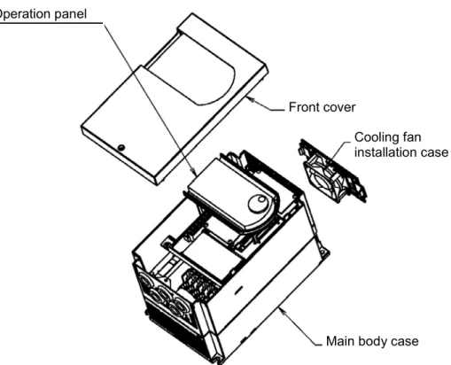
<Names of each part>
Cooling fan installation case
Main body case Front cover
Operation panel
Fig. 1 For N018K5, H030K0 and smaller
Main body case Operation panel
Front cover
Fig. 2 For N022K0, X037K0 and larger
Chapter 1 Delivery Inspection and Storage
1-1 Delivery inspection and storage
(1) Remove the inverter from the packaging, and check the details on the rating nameplate to confirm that the inverter is as ordered. The rating nameplate is on the left side of the unit.
(2) Confirm that the product has not been damaged.
(3) If the inverter is not to be used for a while after purchasing, store it in a place with no humidity or vibration in the packaged state.
(4) Always inspect the inverter before using after storing for a long period. (Refer to 8-1.)
1-2 Details of rating nameplate and type display method
(1) The following details are listed on the rating nameplate.
(Note 1) Refer to Chapter 9 for details on UL Instruction. (2) Using the above type as an example, the type is displayed as follows:
VAT300- U3S N002K2 F B S X 0 0 0
Control No.
Indicates future Options.
Indicates if DB is built in the drive. B : DB Built in
N : Without Built in DB Input voltage and capacity
(Refer toAppendix 1) Type Unit U3S : VAT300
VAT300-U3SN002K2FBS AC3PH 380-480V 50/60Hz HD: 3.6A / ND: 5.5A
AC3PH 380-480V - 0.1-440Hz HD: 5.4A / ND: 8.6A
Chapter 2 Installation and Wiring
CAUTION
• Always transport the product with an appropriate amount according to the products weight. Failure to observe this could lead to injuries.
• Install the inverter, dynamic braking unit and resistor, and other peripheral devices on non-combustible material such as metal.
Failure to observe this could lead to fires.
• Do not place the product near inflammable items. Failure to observe this could lead to fires.
• Do not hold the front cover while transporting the product. Failure to observe this could lead to injuries from dropping.
• Do not let conductive materials such as screws or metal pieces and inflammable materials such as oil enter the product.
Failure to observe this could lead to fires.
• Install the product in a place that can withstand the weight of the product, and follow the instruction manual.
Failure to do so could lead to injuries from dropping.
• Do not install and operate an inverter that is damaged or that has missing parts. Failure to observe this could lead to injuries.
• Always observe the conditions described in the instruction manual for the installation environment. Failure to observe this could lead to faults.
2-1 Installation environment
Observe the following points when installing the inverter.
(1) Install the inverter vertically so that the cable lead-in holes face downward. (2) Make sure that the ambient temperature is –10°C to 50°C. (Refer to Appendix 1.) (3) Avoid installation in the following environment.
Place subject to direct sunlight Place subject to wind, rain or water Place with high levels of humidity
Place subject to oil drops Place where dust, cotton lint or iron
Place with harmful corrosive or explosive gases or fluids are present
Place near sources of vibration such as dollies or press machines
Place where flammable materials are present
Place with high levels of ambient temperature
Places with high levels of magnetic noise
Places where radioactive substances are present
(4) Ensure ventilation space around the inverter. (Refer to Fig. 2-1.)
VAT300
200m
m
150m
m
50mm
50mm VAT300
200m
m
200m
m
50mm 50mm
2-2 Installation and wiring method
Installation and wiring for the N018K5S and X030K0 and below, and the wiring for the N022K0 and X037K0 and above are carried out with the front cover removed. The operation panel is fixed with the latches for the operation panel mounting holder, so the front cover can be removed with the operation panel attached.
To remove the operation panel, securely hold the panel with a thumb on the lower side and another finger on the top side as shown in Fig. 2-2-a, and pull the panel forward and off. To mount the operation panel, hold it the top and bottom sides with five fingers, and press the panel on horizontally. Confirm that the operation panel is securely fixed with the latches for the operation panel mounting holder.
The operation panel mounting holder opens and closes with the right side as a base point as shown in Fig. 2-2-b. When wiring to the control terminal block, open the left side of the main body case outward, and open the folder to 90°. When closing after wiring, confirm that the jaw on the left end of the holder is securely fit into the hole on the main body case.
(1) N018K5S, X030K0 and smaller (Fig. 2-2-c)
Fix the VAT300 at four places when installing. The lower two installation sections are notched. Remove the front cover, and wire to the main circuit and control terminal block.
VAT300 mounting hole (Total 4 bolts)
Cooling fan
Main body case Front cover Confirm that the holder
jaw is fit into the hole.
Open the main body case outward and open the holder.
Open/close up to 90°
Operation panel and holder
Fig. 2-2-b
(2) N022K0, X037K0 and larger (Fig. 2-2-d)
Fix the VAT300 at four places when installing. The VAT300 mass is more than 25kg, so installation by two workers is recommended. When two workers are installing the unit, they should confirm each step with signals. Wire in the same manner as step (1).
VAT300 mounting hole (Total 4 bolts)
Operation panel
Main body case
Front cover
2-3 Precautions for power supply and motor wiring
DANGER
• Always turn the device's input power OFF before starting wiring. Failure to do so could lead to electric shocks or fires.
• Carry out grounding that complies with the standards of the country where the inverter is being installed.
Failure to do so could lead to electric shocks or fires.
• When using the PM motor, even if the inverter is stopped, the voltage will be generated at the output terminal (U, V, W) during rotation. Always carry out wiring while the motor is stopped.
Failure to do so could lead to electric shocks or injuries. • Wiring must always be done by a qualified electrician. Failure to observe this could lead to electric shocks or fires. • Always install the device before starting wiring.
Failure to do so could lead to electric shocks or injuries.
• Prepare a breaker such as a Molded Case Circuit Breaker(MCCB) or fuse that matches the capacity for the inverter's power supply side.
Failure to do so could lead to fires.
CAUTION
• Do not connect an AC power supply to the output terminals (U, V, W). Failure to observe this could lead to injuries or fires.
• Confirm that the product's rated voltage and frequency match the power supply voltage and frequency. Failure to do so could lead to injuries or fires.
• Install an overheating protection device on the dynamic braking resistor, and shut off the power with an error signal.
Failure to do so could lead to fires in the event of abnormal overheating.
• Do not directly connect a resistor to the DC terminals (between L+1, L+2 and L–). Failure to observe this could lead to fires.
• Tighten the terminal screws with the designated tightening torque. Failure to do so could lead to fires.
• Correctly connect the output side (U, V, W).
Failure to observe this could lead to reverse rotation of the motor, and to injuries or machine damage.
• Always correctly connect when using the encoder.
The signal polarity specifications differ according to the encoder. Refer to sections 3-4-2 (4) and 3-4-3(1) on test operation, and adjust the signal polarity with the parameter settings (C50, C51). Failure to observe this could lead to reverse rotation or abnormal acceleration of the motor, and to injuries or machine damage.
Refer to Fig. 2-3-a and wire the main circuits for the power supply and motor, etc. Always observe the following precautions for wiring.
CAUTION
There is a risk of electric shocks.
The VAT300 has a built-in electrolytic capacitor, so a charge will remain even when the inverter power is turned OFF. Always observe the followings before carrying out wiring work.
• Wait at least 10 minutes after turning the power OFF before starting work. Make sure that the displays on the operation panel have gone out before removing the cover.
(a) N018K5, X022K0 and smaller
MC
1 4
2 5
3 6
E E
L+1 B MCCB (Note 1) U V W (Note 1) L1 L2 L3 L+2 DCL L-VAT300 M MC (Note 3) (Note 9) (Note 10) 76D DB resistor
(Note 11)
(Note 6) (Note 8)
Noise filter (Note 7) ACL (Note 6) (Note 9) (Note 2)
Power supply (Note 5)
(Note 13) (Note 12)
(Note 15)
(Note 7)
(Note 14)
(b) N022K0 to N045K0, X030K0 to X055K0
MC
VAT300 M
1 4 2 5 3 6 E E
N P DB
L+2
L+1 L−
MCCB MC
(Note 3) (Note 9) (Note 7) (Note 10) DB resistor DCL (Note 11) (Note 6) (Note 5) DB unit (Note 8) (Note 1) U V W (Note 1) L1 L2 L3 Noise filter (Note 7) ACL (Note 6) (Note 9) (Note 2) Power supply (Note 13) (Note 12) (Note 14)
(c) X075K0 to X475K0
JP-1 (380V-415V) DCL
1 4
2 5
3 6
E E
M L-N DB P L+2 L+1 VAT300 MCCB U V W (Note 1) L1 L2 L3 MC (Note 3) (Note 9) (Note 7) (Note 10) (Note 11) (Note 6) (Note 5) DB unit (Note 8) Noise filter (Note 7) ACL (Note 6) (Note 9) (Note 2)
Power supply (Note 13)
(Note 12) DB resistor
(Note 1)
(Note 1) Configuration of inverter's main circuit
The inverter input terminals are L1, L2 and L3. The output terminals to the motor are U, V and W. Do not connect the power supply to the U, V, W terminals. Incorrect wiring will lead to inverter damage or fires.
The VAT300 main circuit configuration is largely divided into three types according to the capacity zone.
(1) The first type is the N011K0/X015K0 and smaller capacities. The L+1 and L+2 terminals are located in the step before the pre-charge circuit. The DB circuit is built-in, and the use of the built-in DB resistor can be selected with options. The use of the built-in EMI filter can also be selected with options. Note that the external EMI filter must be used for the N007K5 and N011K0 capacity.
With the N011K0/X015K0 and smaller capacity, the L+2 and L- terminals for connecting the PWM converter are provided as a standard. Contact the inverter dealer when using the PWM converter.
(2) The second type is the N015K0, N018K5/X018K5, and X022K0 capacities. The L+1 and L+2 terminals are located in the step after the pre-charge circuit. The DB circuit is built-in, but the DB resistor must be prepared by the customer. With the X018K5 and X022K0 capacities, the use can be selected with the built-in EMI filter options. Use an external EMI filter with the N015K0 and N018K5 capacities.
(3) The third type is the N022K0/X030K0 and larger capacities. The L+1 and L+2 terminals are located in the step after the pre-charge circuit. The built-in DCL can be selected as an option. A standalone DCL can also be selected. With the X030K0, the use of the built-in EMI filter can be selected with options. Use an external EMI filter with the
N022K0/X037K0 and larger capacities.
*1) Incompatible with N007K5 and N011K0
(1) N011K0/X015K0 and smaller capacities
L+1 L+2 B
L1
L2
L3
U
V
W Standalone
DC reactor (option)
L-Built-in DB resistor (option)
VAT300
Built-in EMI filter (option)
*2) Incompatible with N015K0 and N018K5
(2) N015K0, N018K5/X018K5, X022K0
L+1 L+2
L1
L2
L3
U
V
W Additional/
standalone DC reactor (option) *3
L-VAT300
Built-in EMI filter
(option) *4
Standalone DB unit (option)
L+1 L+2 B
L1
L2
L3
U
V
W Standalone
DC reactor (option)
VAT300
External DB resistor (prepared by customer)
Built-in EMI filter
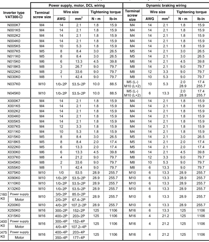
(Note 2) Wire size
Use wires having the wire size shown in Table 2-3-a and Table 2-3-b for the main circuit wiring shown in Fig. 2-3-a.
Table 2-3 gives the screw sizes, applicable wire sizes and tightening torque for the main circuit terminal shown in Fig. 2-3-b.
Table 2-3-a Terminal and applicable wire (for normal-duty)
Power supply, motor, DCL wiring Dynamic braking wiring
Wire size Tightening torque Wire size Tightening torque Inverter type
VAT300 U3S_
Terminal screw size
AWG mm2 N • m lb-in
Terminal screw
size AWG mm2 N • m lb-in
N000K7 M4 14 2.1 1.8 15.9 M4 14 2.1 1.8 15.9
N001K5 M4 14 2.1 1.8 15.9 M4 14 2.1 1.8 15.9
N002K2 M4 14 2.1 1.8 15.9 M4 14 2.1 1.8 15.9
N004K0 M4 10 5.3 1.8 15.9 M4 14 2.1 1.8 15.9
N005K5 M4 8 8.4 1.8 15.9 M4 14 2.1 1.8 15.9
N007K5 M5 8 8.4 3.0 26.5 M5 14 2.1 3.0 26.5
N011K0 M5 6 13.3 3.0 26.5 M5 14 2.1 3.0 26.5
N015K0 M6 3 26.7 4.5 39.8 M6 14 2.1 4.5 39.8
N018K5 M8 2 33.6 9.0 79.7 M8 12 3.3 9.0 79.7
N022K0 M8 1 42.4 9.0 79.7 M8 10 5.3 9.0 79.7
N030K0 M8 1/0×2P 53.5×2P 9.0 79.7 M8 10 5.3 9.0 79.7
N037K0 M10 1/0×2P 53.5×2P 10.0 88.5 M5 (L-)
M10 (L+2) 6 13.3
2.0 28.9
17.4 255.7
N045K0 M10 1/0×2P 53.5×2P 10.0 88.5 M5 (L-)
M10 (L+2) 6 13.3
2.0 28.9
17.4 255.7
X000K7 M4 14 2.1 1.8 15.9 M4 14 2.1 1.8 15.9
X001K5 M4 14 2.1 1.8 15.9 M4 14 2.1 1.8 15.9
X002K2 M4 14 2.1 1.8 15.9 M4 14 2.1 1.8 15.9
X004K0 M4 14 2.1 1.8 15.9 M4 14 2.1 1.8 15.9
X005K5 M4 12 3.3 1.8 15.9 M4 14 2.1 1.8 15.9
X007K5 M4 10 5.3 1.8 15.9 M4 14 2.1 1.8 15.9
X011K0 M4 8 8.4 1.8 15.9 M4 14 2.1 1.8 15.9
X015K0 M5 8 8.4 3.0 26.5 M5 14 2.1 3.0 26.5
X018K5 M5 6 13.3 2.0 17.4 M5 14 2.1 2.0 17.4
X022K0 M5 6 13.3 2.0 17.4 M5 14 2.1 2.0 17.4
X030K0 M6 4 21.2 4.5 39.8 M6 12 3.3 4.5 39.8
X037K0 M8 2 33.6 9.0 79.7 M8 10 5.3 9.0 79.7
X045K0 M8 1 42.4 9.0 79.7 M8 6 13.3 9.0 79.7
X055K0 M8 1/0 53.5 9.0 79.7 M8 6 13.3 9.0 79.7
X075K0 M10 1/0×2P 53.5×2P 28.9 255.7 M10 6 13.3 28.9 255.7
X090K0 M10 1/0×2P 53.5×2P 28.9 255.7 M10 6 13.3 28.9 255.7
X110K0 M10 1/0×2P 53.5×2P 28.9 255.7 M10 6 13.3 28.9 255.7
Power supply 3/0×2P 85.0×2P X132
K0 Motor M10 2/0×2P 67.4×2P 28.9 255.7 M10 6 13.3 28.9 255.7
X160K0 M10 4/0×2P 107.2×2P 28.9 255.7 M10 6 13.3 28.9 255.7
X200K0 M10 300×2P 152×2P 28.9 255.7 M10 6 13.3 28.9 255.7
X250K0 M16 400×2P 203×2P 125 1106 M16 4 21.2 125 1106
Power supply 300×4P 152×4P X315
K0 Motor M16 4/0×4P 107.2×4P 125 1106 M16 4 21.2 125 1106
Power supply 400×4P 203×4P X400
K0 Motor M16 350×4P 177×4P 125 1106 M16 4 21.2 125 1106
Table 2-3-b Terminal and applicable wire (for heavy-duty)
Power supply, motor, DCL wiring Dynamic braking wiring
Wire size Tightening torque Wire size Tightening torque Inverter type
VAT300-
Terminal
screw size AWG mm2
N • m lb-in
Terminal screw
size AWG mm2 N • m lb-in
N000K7 M4 14 2.1 1.8 15.9 M4 14 2.1 1.8 15.9
N001K5 M4 14 2.1 1.8 15.9 M4 14 2.1 1.8 15.9
N002K2 M4 14 2.1 1.8 15.9 M4 14 2.1 1.8 15.9
N004K0 M4 14 2.1 1.8 15.9 M4 14 2.1 1.8 15.9
N005K5 M4 10 5.3 1.8 15.9 M4 14 2.1 1.8 15.9
N007K5 M5 8 8.4 3.0 26.5 M5 14 2.1 3.0 26.5
N011K0 M5 8 8.4 3.0 26.5 M5 14 2.1 3.0 26.5
N015K0 M6 6 13.3 4.5 39.8 M6 14 2.1 4.5 39.8
N018K5 M8 3 26.7 9.0 79.7 M8 14 2.1 9.0 79.7
N022K0 M8 2 33.6 9.0 79.7 M8 12 3.3 9.0 79.7
N030K0 M8 1 42.4 9.0 79.7 M8 10 5.3 9.0 79.7
N037K0 M10 1/0×2P 53.5×2P 10.0 88.5 M5 (L-)
M10 (L+2) 10 5.3
2.0 28.9
17.4 255.7
N045K0 M10 1/0×2P 53.5×2P 10.0 88.5 M5 (L-)
M10 (L+2) 6 13.3
2.0 28.9
17.4 255.7
X000K7 M4 14 2.1 1.8 15.9 M4 14 2.1 1.8 15.9
X001K5 M4 14 2.1 1.8 15.9 M4 14 2.1 1.8 15.9
X002K2 M4 14 2.1 1.8 15.9 M4 14 2.1 1.8 15.9
X004K0 M4 14 2.1 1.8 15.9 M4 14 2.1 1.8 15.9
X005K5 M4 14 2.1 1.8 15.9 M4 14 2.1 1.8 15.9
X007K5 M4 12 3.3 1.8 15.9 M4 14 2.1 1.8 15.9
X011K0 M4 10 5.3 1.8 15.9 M4 14 2.1 1.8 15.9
X015K0 M5 8 8.4 3.0 26.5 M5 14 2.1 3.0 26.5
X018K5 M5 8 8.4 2.0 17.4 M5 14 2.1 2.0 17.4
X022K0 M5 6 13.3 2.0 17.4 M5 14 2.1 2.0 17.4
X030K0 M6 6 13.3 4.5 39.8 M6 14 2.1 4.5 39.8
X037K0 M8 4 21.2 9.0 79.7 M8 12 3.3 9.0 79.7
X045K0 M8 2 33.6 9.0 79.7 M8 10 5.3 9.0 79.7
X055K0 M8 1 42.4 9.0 79.7 M8 6 13.3 9.0 79.7
X075K0 M10 1/0 53.5 28.9 255.7 M10 6 13.3 28.9 255.7
X090K0 M10 1/0×2P 53.5×2P 28.9 255.7 M10 6 13.3 28.9 255.7
X110K0 M10 1/0×2P 53.5×2P 28.9 255.7 M10 6 13.3 28.9 255.7
X132K0 M10 1/0×2P 53.5×2P 28.9 255.7 M10 6 13.3 28.9 255.7
Power supply 3/0×2P 85.0×2P X160
K0 Motor M10 2/0×2P 67.4×2P 28.9 255.7 M10 6 13.3 28.9 255.7
X200K0 M10 4/0×2P 107.2×2P 28.9 255.7 M10 6 13.3 28.9 255.7
X250K0 M16 300×2P 152×2P 125 1106 M16 6 13.3 125 1106
X315K0 M16 400×2P 203×2P 125 1106 M16 4 21.2 125 1106
Power supply 300×4P 152×4P X400
K0 Motor M16 4/0×4P 107.2×4P 125 1106 M16 4 21.2 125 1106
Power supply 400×4P 203×4P X475
(Note 3) Breaker for wiring
Install a Molded Case Circuit Breaker(MCCB), fuse or magnetic contact (MC) on the inverter's power supply side. Refer to Table 7-1-b and select the MCCB or Fuses.
When using as a UL/cUL Standard certified product, install the UL certified fuse as explained in section 9-1.
(Note 4) Selection of power voltage for auxiliary equipment power supply
For the 400V Series (X075K0 and larger), switch the auxiliary equipment power supply selection connector according to the rated voltage of the power being used. If the following settings do not apply to the power voltage being used, select the closest power voltage.
For 380V to 415V, short circuit across JP-1 For 416V to 460V, short circuit across JP-2
For 461V to 480V, short circuit across JP-3 (factory setting state)
(Note 5) Power voltage/frequency
Prepare the power supply to match the following power voltage and frequency.
Voltage system Type Power voltage Frequency
L series N000K7 to N011K0 200 to 240V ± 10% 50/60Hz ± 5%
N015K0 to
N045K0 200 to 230V ± 10% 50/60Hz ± 5%
H series X000K7 to
X475K0 380 to 480V ± 10% 50/60Hz ± 5%
(Note 6) Power supply capacity
Make sure that capacity of the transformer used as the inverter's power supply is within the following range. (For 4% impedance transformer)
Heavy-duty rating (N045K0, X055K0 and smaller) ... 500kVA or less
Heavy-duty rating (X075K0 and larger), Normal-duty ... Capacity that is 10-times or less inverter capacity
If the above values are exceeded, install an ACL on the inverter's input side. (Refer to Table 7-1-b.)
FAN
MC
JP-1 JP-2 JP-3
From power input L1
From power input L2
Transformer AUX PCB Gate drive PCB
Tap selection connector
(Note 7) Noise measures
The inverter will generate high harmonic electromagnetic noise, so using the following noise measures is recommended.
a) Insert an EMC filter on the input side of the inverter. Refer to Table 7-1-b and select the EMC filter. A unit with built-in noise filter is available as an option.
b) Keep the length of the wire between the EMC filter and inverter as short as possible, and wire it as far away from the noise filter's power supply side.
c) Use a shield cable for the inverter and motor wiring, and connect the shield to the inverter's terminal and motor grounding terminal. Note that if the cable is long, the higher harmonic leakage current may increase, the overcurrent limit function may malfunction, and in extreme cases, the current detector in the unit could be damaged. In this case, lower the carrier frequency as low as possible, and increase the inverter capacity as required.
d) Separate the main circuit wiring from the control circuit wiring. Do not place the wires in the same conduit, lay them in parallel or bundle them, etc. If the wires must be laid in parallel, separate them by 30cm or more, and pass each through a metal conduit. If the wires need to be intersected, make sure that they intersect at a right angle.
(Note 8) Inverter output
a) Do not insert a power factor improvement capacitor on the output side of the inverter. b) When inserting a magnetic contactor on the output side of the inverter, prepare a
sequence control circuit so that the magnetic contactor will not open and close when the inverter runs.
c) Directly connect the motor to the inverter's load. Do not connect relay it through a transformer or Slidac, etc.
(Note 9) Grounding
Always ground the inverter unit grounding terminal and the ground. Ground according to the regulations of the country where the inverter is being used.
(Note 10)Inverter output surge voltage (For 400V series)
If the wiring between the inverter and motor is long (20m or more), the surge voltage applied on the motor will increase, and the motor insulation could deteriorate. In this case, lower the carrier frequency as low as possible (4kHz or less), and use a motor with reinforced insulation for inverter drive, or connect a surge absorber dedicated for the inverter output.
(Note 11) DCL
Always short circuit across L+1 and L+2 when not using the DCL. (Factory setting state) When connecting the optional DCL, connect it to L+1 and L+2.
Always remove the short-circuit bar at this time.
Twist the wiring to DCL, and keep it as short as possible.
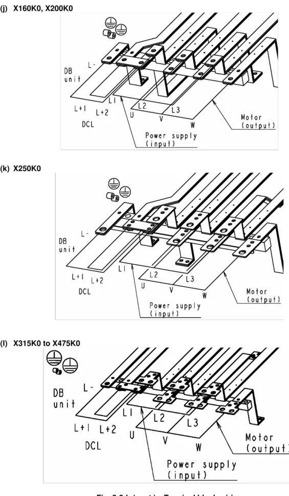
(Note 12) DB (Dynamic Braking) unit (N022K0, X030K0 or more)
When connecting the optional DB unit, follow Fig. 2-3-a (b) (c) and connect the L+2 and L–. The DB unit and inverter unit will both be damaged if the connection is incorrect.
Twist the wiring to the DB unit, and keep it as short as possible (3m or less). Refer to Section 7-3 for details.
(a) N000K7 to N011K0 (b) X018K5, X022K0 X000K7 to X015K0
(c) N015K0 (d) X030K0
DB Unit
L-(e) N018K5
(f) N022K0, N030K0 (g) N037K0, N045K0 X037K0 to X055K0
(h) X075K0, X090K0
(i) X110K0, X132K0 DB Unit
(j) X160K0, X200K0
(k) X250K0
(l) X315K0 to X475K0
2-4 Precautions for wiring to the control signal
(1) When wiring (control circuit wiring) to the control terminal block, separate the main circuit wiring (terminals L1, L2, L3, L+1, L+2, L–, B, U, V, W) and the other drive wires and power wires. Do not place the wires in the same conduit, lay them in parallel or bundle them, etc.
(2) Use a 0.13 to 0.8mm² wire for wiring to the control circuit.
In this case, tighten TB1 and TB2 with a 0.6N·m tightening torque. The TB3 tightening torque must be 0.25N·m.
(3) The length of the sequence input/output contact wire must be 30m or less.
(4) The sequence output PSO3 can output the pulse output (max.: 6kHz) by changing DS1-4 and setting the pulse output.
When using the speed detection option, do not set the pulse output if using the pulse output function provided with the option.
(5) Use a twisted pair wire or twisted pair shield wire for wiring to the analog signal circuit such as the setters and meter. (Refer to Fig. 2-4-a.) Connect the shield wire to the TB1 COM terminal of the VAT300.
The wire length must be 30m or less.
(6) The analog output is dedicated for the indicators such as the speedometer and ammeter. It cannot be used for control signals such as the feedback control.
(7) RY24 and RY0 are designed exclusively for the drive's internal sequence circuits. These are not designed to supply power to any external devices.
(8) After wiring, always check the mutual wiring.
At this time do not carry out a megger check or buzzer check on the control circuit. • Are there any wire scraps or foreign matter left around the terminals?
• Are any screws loose? • Is the wiring correct?
• Is any terminal contacting any other terminal?
F A VAT300 +15V 0V 0V 0VOP RY RY 11kΩ 2kΩ
2W 10kΩ
750Ω
Analog output • Changeable to 0 to 10V
or 4 to 20mA 0 to 10V max. 1mA 4 to 20mA max. 500Ω
• All terminal functions can be changed. Serial communication (RS-485)
CN2 and TB3 cannot be used simultaneously. 2 4 1 5VOP Terminator PSO1 PSO2 PSO3 PSOE DATA+ 0VOP 5VOP DATA+ DATA- 0VOP 3
CN2 : Modular Connector
PSI1 PSI2 PSI3 PSI4 PSI5 PSI6 PSI7 RY0 4.7kΩ RY24V 4.7kΩ RY0V Sink Source Sink/source logic changeover RY24 510Ω 11kΩ 10kΩ 510Ω 20kΩ P10 AI1 AI2 AI3 COM 0V 0V COM AO1 AO2 COM COM RY24V RY0V RA RC FA FB FC Sequence output (Relay output) • RA-RC Max. 250VAC 1A Max 30VDC 1A • FA-FB-FC
Max. 125VAC 0.4A Max. 30VDC 1A • All terminal functions can
be changed.
Sequence output (Open collector output)
• Max. 30VDC 50mA • PS03 can be changed to
pulse output • All terminal functions can
be changed. Sequence input
• 5mADC
• PSI7 can be changed to pulse input
• All terminal functions can be changed. Analog input
• AI1, AI2
Changeable to voltage signal or current signal Voltage signal max. 10VDC Current signal max. 20mADC • A13 max. ±10VDC • All terminal functions can
be changed. Frequency setting 20kΩ DATA- Forward run Reset Signal Emergency stop Reverse run Forward jog Reverse jog Run Fault READY 1 Current detection Speed attained (Note2) 1 1 W2 W1 2 2 (Note1) (Note1) (Note1) (Note4) (Note4) (Note3) (Note5)
TB3 : Terminal
Fig. 2-4-a
(Notes)
1. Four COM terminals are internally connected.
2. No connection shall be made between RY0, COM and 0VOP since this section is insulated. 3. This diagram is an example of the sink logic connection.
4. RY24 and RY0 must not be shorted. 5. P10 and COM must not be shorted.
Fig. 2-4-b
DS1
TB2
PSI5 PSI7 PSO2 PSOE FB FC FA
PSI4 PSI6 PSO1 PSO3 RY0 RC RA
CN2 TB1
AI1 AO1 AO2 RY24 PSI2
COM COM PSI1 PSI3
AI3
COM AI2
COM P10
2 2 1 W1 1 W2 W4 2 1 2 1 W3
SG D- D+
1 2 3 4 ON
1) Control terminal TB1,TB2
• The terminal block is laid out in two rows.
• Terminal screw size is M3.
2) Dip switches DS1
No. OFF ON Signal
1 OPEN 120Ω Standard serial terminator changeover 2 V1 I1 AI1 voltage, current changeover 3 V2 I2 AI2 voltage, current changeover
4 PS03 PULSE Sequence output, pulse train output changeover
All switches are set to OFF as the default.
3) EL-BIT W1,W2,W3,W4
No. 1 2 Signal
W1 SINK SOURCE PSI1~6 sink,source changeovers W2 SINK SOURCE PSI7 sink,source changeover W3 voltage current AO1 voltage, current changeover W4 voltage current AO2 voltage, current changeover
All EL-BITs are set to 1 as the default.
4) Standard serial or Modbus transmission
CN2 (Connector type: 4-pole modular, Hirose Electric TM3P-44P or equivalent)
• A signal level is based RS-485. The terminus resistance (120Ω) can set up on/off in DS1-1. ((DS1-1=120Ω): Connected, (DS1-1=OPEN): Not connected)
• The direction of a signal is based on VAT300.
• 5VOP and 0VOP are not designated to supply power externally.
Terminal No. Signal
1 DATA+ 2 DATA- 3 0VOP 4 5VOP
5) Standard serial or Modbus transmission TB3
• CN2 and TB3 DATA+, DATA- and 0VOP are connected in the PCB.
• The terminal size is M2.
• The applicable wire size is AWG26 to AWG16.
Terminal
No. Symbol Signal
1 D+ DATA+ 2 D- DATA- 3 SG 0VOP
Wire peeling size
5mm
5mm
6.6mm
Outline drawing of connector
Notes for moving Operation panel holder
Do not raise the operation panel holder with an angle of larger than 90°, so that the holder should not be fallen off.
If the operation panel holder should be taken off, push the hinges of the holder lightly and insert them into the original positions.
Fig. 2-4-c
Chapter 3 Test Operation and Adjustment
DANGER
• Always install the front cover before turning the input power ON. Never remove the cover while the power is ON. There are sections in the front PCB that are charged with high voltages.
Failure to observe this could lead to electric shocks. • Never touch the switches with wet hands.
Failure to observe this could lead to electric shocks.
• Never touch the inverter’s terminals while the inverter power is ON even if the operation is stopped. Failure to observe this could lead to electric shocks.
• Selection of the retry function could lead to unexpected restarting when alarm stops. The machine may start suddenly if the power is turned ON when the automatic start function is selected. Do not go near the machine.
(Design the machine so that physical safety can be ensured even if the machine restarts.) Failure to do so could lead to injuries.
• The machine may not stop when a stop command is issued if the deceleration stop function is selected and the overvoltage/overcurrent limit function is activated. Prepare a separate emergency stop switch.
Failure to do so could lead to injuries.
• The unit will not suddenly restart even if the alarm is reset with the operation signal input, however, in order to prevent unexpected operation, ensure that the operation signal is no longer being input, and reset the alarm.
Failure to do so could lead to injuries.
CAUTION
• The heat sink and resistor are heated to high temperatures, so never touch them. Failure to observe this could lead to burns.
• Do not block the inverter’s ventilation holes. Failure to observe this could lead to fires.
• The inverter operation can easily be set from low speeds to high speeds, so confirm that the operation is within the tolerable range for the motor or machine before making settings. Failure to do so could lead to injuries.
• Prepare holding brakes when necessary. Holding is not possible with the inverter’s brake functions. Failure to do so could lead to injuries.
• Confirm the operation of the motor as a single unit before operating the machine.
Failure to do so could lead to injuries or machine damage due to unforeseen movements.
The VAT300 has various setting items. Some of these include settings that must be made according to the power supply and motor before actually starting operation.
The methods for the VAT300 basic test operation and adjustment are explained in this section.
3-1 Flow of test operation
Carry out test operation according to the flow shown in Fig. 3-1.
The procedures above the dotted line in Fig. 3-1 are explained in this section.
Start
↓
Installation and wiring
↓
Initial power supply
↓
Selection of control mode
↓
Initialization of parameters
↓
Automatic tuning and adjustment
↓
Test operation with operation panel
↓
Setting of parameters for external control
↓
Test operation including external control
↓
End of test operation
Fig. 3-1 Flow of test operation
CAUTION
• Check that the wiring is correct.
• The power supply must always be kept in the tolerable range. • Confirm that the motor rating is within the inverter's rating range. • Always correctly install the front cover before turning the power on. • Assign one worker to operate the switches, etc.
Refer to section 3-4.
Refer to Chapter 2 and section 3-2, and complete the installation and wiring.
Refer to Section 3-3.
Range explained in Chapter 3.
↓
3-2 Preparation before turning power ON
Always confirm the following points before turning ON the power after completing wire.
(1) Remove the coupling and belt coupling the motor and machine, so that the machine can be run as a single unit.
(2) Confirm that the power supply wire is correctly wired to the input terminals (L1, L2, L3).
(3) With the 400V Series (X075K0 or higher), there are some sections in the inverter which operate with an AC power supply, such as fan and magnetic contactor. In this case, set the power changeover connector on the transformer auxiliary PCB according to the power voltage.
If this connector is not set correctly, the fan and magnetic contactor could burn. For 380V to 415V, short circuit across JP-1
For 416V to 460V, short circuit across JP-2
For 461V to 480V, short circuit across JP-3 (factory setting state)
(4) Make sure that the power voltage and frequency are within the tolerable range.
Voltage system Type Power voltage Frequency
200V series N000K7 to N011K0 200 to 240V ± 10% 50/60Hz ± 5% N015K0 to N045K0 200 to 230V ± 10% 50/60Hz ± 5% 400V series X000K7 to X475K0 380 to 480V ± 10% 50/60Hz ± 5%
(5) Refer to section 2-3, and correctly connect the main circuit wiring. (6) Securely fix the motor with the specified method.
(7) Make sure that none of the terminal section screws are loose.
(8) Make sure that there is no short circuit state in the terminals caused by wire scraps, etc. (9) Always correctly install the front cover and outer cover before turning the power ON. (10) Assign an operator, and make sure that the operator operates the switches.
CAUTION
3-3 Control modes
With the VAT300, four control modes and two overload modes can be selected. These are set with the parameter C30-0 (control mode selection). Refer to the Appendix Table 1 Table of control specifications for details.
* C30-0 is set with a 2-digit value (f0, f1). Refer to section 3-4 for the setting methods.
(1) Control modes
There are four VAT300 motor control modes. Refer to the following table, and select the mode which suits the application.
Control mode Explanation C30-0 f0
1) V/f control The voltage - frequency ratio is controlled. 1
2) IM speed sensor-less vector control
The IM is vector-controlled without a speed sensor.
The speed can be controlled. 2
3) IM vector control with speed sensor
The IM is vector-controlled with a speed sensor.
This mode is used when a fast speed response or torque response is required.
The speed detection option 1 is required. (Note 1)
3
4) PM motor control with sensor
The PM motor is vector-controlled.
The motor can be operated at a higher efficiency than IM. A speed detection option which matches the sensor (encoder) being used is required. (Note 1)
4
(Note 1) : Refer to Table 7-1-a (Chapter 7) for details on the speed detection options.
(2) Device overload mode selection
The following two modes can be selected according to the load being used. If the load and device capacity do not differ, the device could be overloaded. Refer to the following table, and select the mode that matches the load being used.
Control mode Explanation C30-0 f1
1) Normal-duty setting
Select this when the maximum load rate in respect to the rated load is low.
The overload standard will be 120% of the motor's rated current for one minute.
1
2) Heavy-duty setting
Select this when the maximum load rate in respect to the rated load is high.
The overload standard will be 150% of the motor's rated current for one minute.
3-4 Automatic tuning and test operation
Automatic tuning measures the constants of the connected motor, and automatically adjusts the parameters so that the system is used to the fullest.
The VAT300 automatic tuning function performs differ measurements for each of the four control modes. Carry out automatic tuning each time the motor being used or the applicable control mode is changed. The automatic tuning mode is set with parameter B19-0 (automatic tuning selection).
Control mode Automatic tuning mode
• V/f control B19-0 = 1,2
• IM speed sensor-less vector control B19-0 = 3, 4, 5 • IM vector control with speed sensor B19-0 = 1, 3, 4, 5 • PM motor control with sensor B19-0 = 6, 7
B19-0 Name
1 Simple adjustment mode
2 V/f control high-function adjustment mode
3 Vector control basic adjustment mode
4 Vector control expanded adjustment mode
5 No-load voltage operation mode
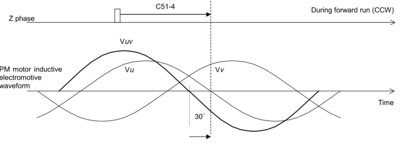
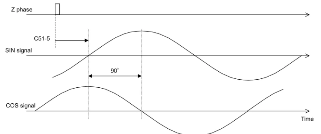
6 Encoder phase adjustment mode (Note 1)
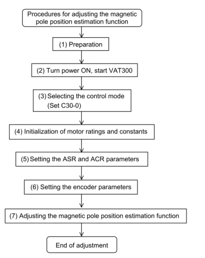
7 Magnetic pole position estimation mode (Note 2)
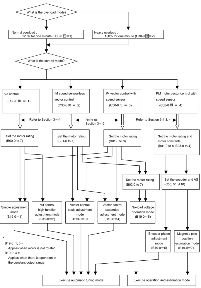
Carry out parameter initialization and automatic tuning as shown in the following flow chart. Refer to Chapter 4 for details on changing the parameters and operating the operation panel.
An adjustment mode dedicated for elevators (with brakes) is provided for the PM motor vector control with speed sensor. Refer to section 3-4-4 when using this mode for elevator applications.
Refer to section 3-4-3 when using for applications other than elevators.
(Note 1) B19-0=6 : The encoder phase adjustment mode automatically adjusts the parameters which set the phase angle between the encoder Z phase pulses and PM motor U-phase coil. The motor circuit constants are not adjusted automatically.
(Note 2) B19-0=7 : The magnetic pole position estimation mode is used to adjust the PM motor control magnetic pole position estimation function. This mode does not
IM speed sensor-less vector control
(C30-0 f0 = 2)
IM vector control with speed sensor
(C30-0 f0 = 3)
PM motor vector control with speed sensor
(C30-0 f0 = 4)
Fig. 3-4 Selection of automatic tuning mode
Simple adjustment mode (B19-0=1) V/f control
(C30-0 f0 = 1)
Refer to Section 3-4-1
V/f control high-function adjustment mode
(B19-0=2)
Vector control basic adjustment
mode (B19-0=3)
Vector control expanded adjustment mode
(B19-0=4)
No-load voltage operation mode (B19-0=5)
Execute automatic tuning mode
Encoder phase adjustment
mode (B19-0=6)
Magnetic pole position estimation mode
(B19-0=7)
Execute operation and estimation mode *
B19-0: 1, 5 =
Applies when motor is not rotated B19-0: 4 =
Applies when there is operation in the constant output range
What is the overload mode?
Normal overload :
120% for one minute (C30-0 f1=1)
What is the control mode?
Set the motor rating (B00-0 to 7)
Set the encoder and AS (C50, 51, A10) Heavy overload :
150% for one minute (C30-0 f1=2)
Refer to Section 3-4-2
Refer to Section 3-4-3, 4
Set the motor rating (B01-0 to 7)
Set the motor rating (B01-0 to 8)
Set the motor rating and motor constants (B01-0 to 8, B03-0 to 4)
3-4-1 V/f control (C30-0 f0 = 1) automatic tuning and test operation
(1) Automatic tuning (V/f control mode)
The following two modes can be selected for the V/f control automatic tuning.
Using B19-0 (automatic tuning selection), select the automatic tuning mode that matches the working conditions.
1) B19-0 = 1: Mode 1: simple adjustment mode (Execution time: approx. 10 seconds)
The basic parameters, such as boost voltage and brake voltage, are adjusted without rotating the motor.
The following parameters shown in Table 3-4-1-a are automatically adjusted by executing Mode 1.
Table 3-4-1-a
Applicable mode Parameter No. Name
C30-0 f0 = 1 B19-0 = 1
A02-2 A03-0 B02-0, 1 B02-4, 5
Manual torque boost setting DC brake voltage
R1: Primary resistance Lσ: Leakage inductance
2) B19-0 = 2: Mode 2: V/f control high-function adjustment mode (Execution time: approx. 1 minute) The parameters related to the slip compensation and max. torque boost are adjusted while rotating the motor.
The magnetic saturation characteristics are measured at the voltage boost, and are adjusted to match the max. torque boost.
The following parameters shown in Table 3-4-1-b are automatically adjusted by executing Mode 2.
Table 3-4-1-b
Applicable mode Parameter No. Name
C30-0 f0 = 1 B19-0 = 2
A02-2 A03-0 B02-0, 1 B02-4, 5 A02-5 A02-6
Manual torque boost setting DC brake voltage
R1: Primary resistance Lσ: Leakage inductance Slip compensation gain Max. torque boost gain
(Note 1) When the V/f control mode (C30-0 f0 = 1) is selected, modes other than B19-0=1, 2 cannot be used. If B19-0 is set incorrectly, set it again.
CAUTION
Precautions for executing V/f control automatic tuning
• Even when Mode 1 is executed, the motor may rotate due to vibration, etc. • If the vibration is large, press the key immediately to stop operation.
• With Mode 2, the motor will automatically start rotating.
• Always check the safety on the load side before executing automatic tuning, regardless of the Mode 1 or 2 setting.
• During automatic tuning, the motor may rotate, so always confirm safety before starting automatic tuning.
• If the automatic tuning function does not end correctly, always turn the inverter power OFF before investigating or confirming the operation.
• Automatic tuning can be started only in the local operation mode (when "LCL" LED on operation panel is ON). Confirm that the "LCL" LED is ON.
• If the motor has an unstable frequency band, automatic tuning may not end normally. In this case, the maximum torque boost function cannot be used.
• If the load is less than 10% and the fluctuation does not occur, automatic tuning can be carried out with the load and machine connected. However, the performance may not be complete.
• Always carry out automatic tuning before using the maximum torque boost function.
(2) Automatic tuning operation procedures (V/f control mode)
Carry out V/f mode automatic tuning with the following procedures. Refer to Chapter 4 for details on using the operation panel.
Automatic tuning end Automatic tuning procedures
(1) Preparation
(2) Turn power ON, start VAT300
(3) Selecting the control mode (Set C30-0)
(4) Initialization of motor ratings (B00-0 to 7)
(5) Input 2 for B19-0, V/f control high-function adjustment mode (5) Input 1 for B19-0
Simple adjustment mode
(6) Start automatic tuning.
Press the or key.
"LCL" LED flickers
(7) During automatic tuning execution
"FLT" LED turns ON E00 : Att-n (For V24OP1)
(For V24OP2) (9) Automatic tuning
abnormal completion (8) Automatic tuning
normal completion
"LCL" LED changes to continuous light, "RUN" LED turns OFF Can the motor
rotate?
Y
N
Automatic tuning standby state
1) Preparation
Separate the motor and load, machine, etc., and confirm the safety on the load side.
2) Turning the power ON and starting VAT300
Turn the power ON. (For U30 V24OP1)
After carrying out an initial check of the operation panel for approx. 5 seconds, the display changes as shown on the right. The "LCL" LED also turns ON.
(For U30 V24OP2)
All LEDs on the numeric display will turn ON for a short time, and then " ", " " and " " will appear.
The "LCL" and "Hz" LEDs will also turn ON.
3) Selecting the control mode
• Set A05-2 to 1. (Set the hardware option function display ON.) • Set the control mode selection: C30-0 f1 f0.
This parameter must be set first. (Note 1)
V/f control mode is to be used, so set C30-0 f0 =1. Set c30-0 f1 f0 as shown below according to the load.
Normal-duty setting: C30-0 f1 f0 = 1 1 Heavy-duty setting: C30-0 f1 f0 = 2 1
(Note 1) The default value is set to V/f control and Normal-duty setting (C30-0=11).
There are some parameters which will change automatically when C30-0 is changed, so also set this first.
4) Initialization of motor constants
Input the motor rating parameters. Set the parameters shown in Table 3-4-1-c. Automatic tuning will automatically change the parameters, so it is recommended to write down the values set in Table 3-4-1-a or Table 3-4-1-b.
Table 3-4-1-c
Applicable mode Parameter No. Name
C30-0 f0 = 1 B19-0 = 1, 2
B00-0 B00-1 B00-2 B00-3 B00-4 B00-5 B00-6 B00-7
Rated input voltage setting [No.] Max/base frequency simple setting [Hz]
Motor rated output [kW]
Rated output voltage [V]
Max. frequency (Note 1) [Hz]
Base frequency (Note 1) [Hz]
Motor rated current [A]
Carrier frequency
(Note 1) The max. frequency cannot be set below the base frequency, and the base frequency cannot be set above the max. frequency.
5) Selecting and executing the automatic tuning mode
Select the automatic tuning mode and execute automatic tuning.
• The operation panel's operation mode must be set to "Local" to execute automatic tuning. Make sure that the "LCL" LED is ON. If not, press the LCLSET +
STOP
keys, and confirm that the "LCL" LED turns ON.
• Set A05-0 to 1. (Set the expanded setting display ON.)
• Using B19-0 (automatic tuning selection), select the automatic tuning mode according to the working conditions. Refer to section 3-4-1 (1) for details on the automatic tuning mode.
• The automatic tuning standby state will be entered when the LCLSET key is pressed.
Output frequency D00-0 OFF.Hz
FWD REV FLT LCL
Hz A %
LCL
• During the automatic tuning standby state and the automatic tuning execution state, the LCL LED will flicker.
• To exit the automatic tuning standby state, press the key.
6) Starting automatic tuning
Automatic tuning will start when the key or key is pressed according to the required rotation direction.
To stop, press the key or input the emergency stop signal (EMS) from the terminal block.
* Once automatic tuning starts, all panel operations other than the STOP , RSTMOD or
keys ( knobs with U30V24OP1) are disabled until the operation ends.
7) During automatic tuning execution
The progression state can be confirmed with D22-0.
8) Normal completion of automatic tuning
When the automatic tuning ends normally, the "LCL" LED will change from a flicker to a stable light. The “RUN” LED will change from a flicker to the OFF state.
Refer to section 3-4-1 (1) for the adjustment items.
9) Abnormal completion of automatic tuning
If automatic tuning ends abnormally, the "FLT" LED will turn ON and a message will appear. Investigate and check according to the error codes.
Refer to section 3-4-5 for details on the error codes.
(3) Test operation (V/f control mode)
When finished with automatic tuning, test run the isolated motor, and make sure that there are no errors.
An example for when the maximum frequency (B00-4) and base frequency (B00-5) are 50Hz is given below.
Use the following procedures to test the operation with the operation panel. Refer to Chapter 4 for details on using the operation panel.
CAUTION
To prevent incorrect operation during the test operation, make sure that signals are not input into the sequence input terminal.
1) To enable operation with the operation panel, confirm that the "LCL" LED is ON. If not, press the
LCL
SET +
STOP
keys, and confirm that the "LCL" LED turns ON.
(ForU30 V24OP1) (For U30 V24OP2)
Upper level : The steps required for tuning are indicated (lit).
3) Press the RSTMOD and display D00-0 on the monitor. Then press the key. Operation will start.
The "FWD" lamp will turn ON, and the display will change from "OFF" to a value display. The value will gradually increase, and after several seconds, will change to "10.00". This is because as the factory settings, the direct setting frequency (A00-0) is set to 10Hz and the acceleration ramp time 1 (A01-0) is set to 10sec.
CHECK
1. Did the motor run?
2. Is the run direction correct? Check the wiring and operation if abnormal. 3. Is the rotation smooth?
4) Press the key and confirm that the motor runs in reverse.
(Note) Do not carry out this step if a load which cannot be run in reverse is connected.
5) Press the key and stop the motor.
6) Press the key. The motor will forward run at the output frequency 10Hz.
Change the frequency to 50Hz with the following operation.
7) Press the RSTMOD key several times. The Display will alternate between " " and
" " (with the U30V24OP1, the 0 section of "A00-0: 10.00Hz" will flicker).
8) Press the LCLSET key once.
The display will stop at " ", and the last digit will flicker. (With the U30V24OP1, the flicker will move to the 2nd decimal digit of the frequency display.)
This completes the preparation for changing the output frequency. The digit to change can be moved with the key. The output frequency can be incremented/decremented with the
keys ( knobs with U30V24OP1).
9) Move the digit with the key, and using the key ( knob with U30V24OP1), raise
the frequency to "50.00Hz". Then, press the LCLSET key. The output frequency will rise to 50Hz.
(Note) The operation panel frequency change operation is set to "Change in real time" (C11-2=1) with the factory shipment settings. Thus, even if the LCLSET key is not pressed,
the frequency will change in real time using the keys ( knobs
with U30V24OP1).
CAUTION
A 10-second acceleration and 20-second deceleration ramp time are set as defaults. The motor will slowly increase its speed to the set value.
When making a setting (using the keys, or knobs with
(U30-V24OP1), check that the motor operates correctly at each increment of approx. 10Hz.
10) Press the RSTMOD key several times, and display D00-0. When the output frequency ("D00-0"
display) reaches 50Hz, press the STOP key.
The display will decrease to "0.00" in several seconds. The "FWD" or "REV" LED will flicker for two seconds while the DC-brake is applied and the motor will stop.
11) Press the key, and test the reverse run at 50Hz.
(Note) Do not carry out this step if a load which cannot be run in reverse is connected.
This completes the test operation with the operation panel.
3-4-2 IM speed sensor-less vector control (C30-0 f0 = 2) and
IM vector control with speed sensor (C30-0 f0 = 3) automatic tuning test operation
(1) Before automatic tuning
When using IM vector control with speed sensor, the speed detection option is required in addition to the VAT300 standard unit.
When using the IM vector control with speed sensor, use with FWD, F.RUN as forward run and Rev, R.RUN as reverse run.
With the VAT300, the counterclockwise rotation (CCW) looking from the motor shaft is defined as forward run, and clockwise rotation (CW) is defined as reverse run.
Forward run (CW) Reverse run (CW)
Fig. 3-4-2-a Definition of VAT300 motor rotation direction
Refer to Table 3-4-2-a, and confirm that the speed detection option compatible with the encoder in use has been prepared. Refer to Chapter 7 for details on the speed detection option.
Table 3-4-2-a
Encoder type Speed detection option (Instruction Manual No.)
1) Complementary output method U30V24DN1 (PCST-3453)
2) Line driver output method U24V24DN2 (PCST-3454)
(2) Outline of automatic tuning (IM vector control mode)
The following four modes can be selected for the IM speed sensor-less vector control or IM vector control with speed sensor automatic tuning.
Using B19-0 (automatic tuning selection), select the automatic tuning mode according to the load conditions. (Note 1)
1) B19-0 = 1: Mode 1: simple adjustment mode (Execution time: approx. 10 seconds) (Note 1)
The basic parameters for IM vector control with speed sensor are automatically adjusted without rotating the motor.
The following parameters shown in Table 3-4-2-b are automatically adjusted by executing Mode 1.
Table 3-4-2-b
Applicable mode Parameter No. Name
C30-0 f0 = 3 B19-0 = 1
B01-9 B02-0, 1 B02-2, 3 B02-4, 5 B02-6, 7
No-load output voltage R1 : Primary resistance
R2’ : Secondary resistance (Note 2)
Lσ : Leakage inductance