Simulation and Analysis of Induced Harmonics
and Reactive Power of a Rotor-Fed Induction
Generator with PWM Inverter
Samiya Zafar, Zohaib Ahmed Siddiqui
Abstract—Rotor Fed Induction generators are an exception to DFIGs. Small scale wind farms are easy to build in remote, windy areas where standalone systems seem ideal choice for electrical power generation. For these systems, rotor excitation is a critical part. The paper does a comparative analysis of inverter schemes i.e. PWM inverter or pure sine wave inverter, the associated harmonic generation and the associated power factor requirements. The simulation results are also presented.
Keywords-Induction generator; harmonics; reactive power; PWM inverter; rotor frequency
I. INTRODUCTION
Wind turbines invariably use induction generators. With the advancements in this area, several methods and configurations of Induction Generator excitation have been proposed. Along with the conventional singly fed Induction generator with stator connected to grid, and the DFIGs with stator and rotor (through VSCs) connected to grid, there can be a method describing a standalone system as rec ently proposed, where the rotor is excited by a 3 phase AC of low frequency and the stator is connected to a 3 phase load, supplying may be to a small town or area [1].
In this method, a wound rotor IG is connected to a wind turbine and its stator winding is connected to load. The rotor windings are to be excited for which there may be used a grid from which voltage may be stepped down, rectified and then inverted to a frequency of interest (usually low, of the order 1 to 5 Hz) and given to the rotor: Or part of the generation may be fed back through a rectifier and transformer after the initial excitation of the system [1].
Figure 1: Rotor excitation block diagram
Samiya Zafar is a Lecturer at dept. of electrical engineering, NED University of engineering & Technology, Karachi Pakistan. [email protected]
Zohaib Ahmed Siddiqui is a Graduate student at ECE Department, University of Waterloo, Waterloo, Canada. [email protected]
The rotor excitation system can be explained by the block diagram in Fig. 1.
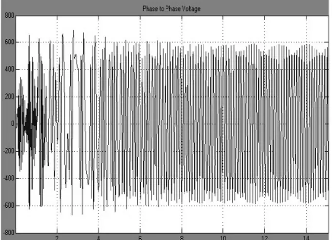
The system is simulated on MATLAB Simulink and also implemented in the lab and is run successfully. The simulation result and the result from the actual prototype implementation are given in Fig. 2 and Fig. 3 respectively.
Figure 2: phase to phase voltage at stator
Figure 3: Induced Voltage at prototype Proceedings of the International MultiConference of Engineers and Computer Scientists 2012 Vol II, IMECS 2012, March 14 - 16, 2012, Hong Kong
ISBN: 978-988-19251-9-0
ISSN: 2078-0958 (Print); ISSN: 2078-0966 (Online)
Here the choice of Inverter that feeds the rotor plays a significant role as that would decide the harmonics induced in the stator. Different types of inverters were studied for their cost and THD and finally PWM inverters are used. Simulation results (from MATLAB) and their analysis are included in the paper. Reactive power requirement of this system is also studied.
Where
IF: RMS value of the fundamental current
In: RMS value of the harmonic n
(2)
II. SINE WAVE AND THE PWM INVERTER
With the increasing popularity of alternate power sources, such as solar and wind, the need for static inverters to convert dc energy stored in batteries to conventional ac form has increased substantially [2].
There are basically two kinds of dc-ac inverters on the market today. One category is the “pure sine-wave” inverter, which produces sine waves with total harmonic distortion (THD) in the range of 3% (-30 dB). These are typically used when there is a need for clean, near-sine-wave outputs for medical, instrument and other critical applications [2].
More recent designs used pulse-width modulation (PWM) to produce a pulsed waveform that can be filtered relatively easily to achieve a good approximation to a sine wave. The significant advantage of the PWM approach is that switching techniques are used in the power stages, resulting in relatively high efficiency. However, PWM, with the pulse width made to vary according to the amplitude of a sine wave, requires significant control circuitry and high-speed switching. This is because the frequency of the PWM signal has to be much higher than that of the sine wave to be synthesized if the PWM signal is to be filtered effectively [2].
The inverter provides a fundamental voltage at the slip frequency and the associated low frequency harmonics can cause a pulsating air gap torque and voltage fluctuations on the system bus bar [3].
Such low frequency harmonics can also exist in a PWM inverter having a high switching frequency. In wind power systems, pulsating torque and flicker have already occurred caused by a fluctuating input due to wind speed. It is also considered that harmonics transfer from the rotor to the stator side of the machine, which was assumed to follow the transformer principle, i.e. magneto motive force (mmf) balance on both sides [3].
III. SIMULATION AND
ANALYSIS
The rotor of an RFIG is energized by a pure sine wave inverter first and then by a PWM IGBT inverter and the stator induced voltage is analyzed for total harmonic distortion. The Fourier analysis is carried out and active and reactive power requirements of rotor with these inverters are studied.
A. Total Harmonic Distortion
The THD is defined as the root mean square (RMS) value of the total harmonics of the signal, divided by the RMS value of its fundamental signal [4]. For example, for currents, the THD is defined as in (1).
(1)
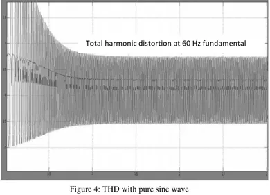
For the pure sine wave inverter, the THD is observed in the stator generated voltage as in Fig. 4.
Figure 4: THD with pure sine wave inverter
For the PWM inverter, the THD is observed as in Fig. 5.
Figure 5: THD with PWM inverter
B. Fourier Analysis
Recall that a signal f (t) can be expressed by a Fourier series of the form as in (3).
(3)
Total harmonic distortion at 60 Hz fundamental
Total harmonic distortion at 60 Hz fundamental
Proceedings of the International MultiConference of Engineers and Computer Scientists 2012 Vol II, IMECS 2012, March 14 - 16, 2012, Hong Kong
ISBN: 978-988-19251-9-0
ISSN: 2078-0958 (Print); ISSN: 2078-0966 (Online)
Where n represents the rank of the harmonics (n = 1 corresponds to the fundamental component) [4]. The magnitude and phase of the selected harmonic component are calculated by (4) and (5).
(4)
(5)
With the pure sine wave inverter, the Fourier analysis on a fundamental frequency voltage of 60 Hz as produced by stator is as given in Fig. 6.
Figure 6: Fourier analysis with pure sine wave inverter
With the PWM inverter, the Fourier analysis on a fundamental frequency voltage of 60 Hz, at a 3rd harmonic and 7th harmonic, as produced by stator is given in Fig. 7.
Figure 7: Fourier analysis with PWM inverter
C. Rotor active and reactive power consumption
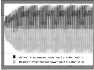
The consumption of active and reactive power by the rotor of an RFIG is an important aspect to be analyzed. For pure sine wave inverter, the rotor consumed powers (both active and reactive) are simulated and the results are as in Fig. 8.
Figure 8: active and reactive power consumption of rotor for sine wave inverter
Similarly, for PWM inverter fed rotor, the active and reactive power requirements are given in Fig. 9.
Figure 9: active and reactive power consumption of rotor for PWM inverter
Note that the reactive power requirement is actually decreased with the PWM fed inverter.
It is important to note here that no filters have been used at any stage from the inverter at the rotor side to the stator output. If a filter is used at the rotor or preferably at the output with stator (since the harmonics there are of frequencies 180 Hz and above), the harmonic contents may be reduced to almost a negligible amount.
Fourier analysis at fundamental frequency of 60 Hz
Active instantaneous power input at rotor (watts)
Reactive instantaneous power input at rotor (vars)
Fundamental component at 60 Hz 3rd harmonic
7th harmonic
Active instantaneous power input at rotor (watts)
Reactive instantaneous power input at rotor (vars)
Proceedings of the International MultiConference of Engineers and Computer Scientists 2012 Vol II, IMECS 2012, March 14 - 16, 2012, Hong Kong
ISBN: 978-988-19251-9-0
ISSN: 2078-0958 (Print); ISSN: 2078-0966 (Online)
IV. CONCLUSION
This paper performed a comparative analysis and simulation of the characteristics of a rotor-fed induction generator using MATLAB simulation approach.
The simulation study shows that the characteristics are affected by the type of inverter used at rotor. Pure sine wave inverters with filter stages are always the preferred choice when it comes to avoid harmonic distortion, yet PWM inverters can be used to get the desired results with actually low reactive power requirement than pure sine wave inverters.
REFERENCES
[1] Samiya Zafar “Simulation and analysis of a prototype rotor fed induction generator for wind power: Parameter controlling using MATLAB” in Proc. IEEE 10th Int. Conf. Environment and Electrical Engineering (EEEIC), 2011, Rome, Italy.
[2] James H. Hahn, “Modified Sine-Wave Inverter Enhanced”,
www.powerelectronics.com, August 2006.
[3] Yong Liao, Li Ranm Ghanim A. putrus and Kenneth S. Smith, ”Evaluation of the effects of rotor Harmonics in a doubly fed induction generator with harmonics induced speed ripple” , IEEE transactions on energy conversion, Vol 18, No. 4 December 2003. [4] MATLAB R2008b, Simulink Help.
Proceedings of the International MultiConference of Engineers and Computer Scientists 2012 Vol II, IMECS 2012, March 14 - 16, 2012, Hong Kong
ISBN: 978-988-19251-9-0
ISSN: 2078-0958 (Print); ISSN: 2078-0966 (Online)