Brazilian Microwave and Optoelectronics Society-SBMO received 31 Mar 2018; for review 5 Apr 2018; accepted 22 Sept 2018 Brazilian Society of Electromagnetism-SBMag © 2018 SBMO/SBMag ISSN 2179-1074
WCIP Method Applied To Modeling an
L-Notched Rectangular Metallic Ring FSS for
Multiband Applications and its Equivalent
Structure
Ibtissem Adoui1, Mohammed Titaouine1,2, Hassina Choutri1, Raouia Saidi2, Thayuan Rolim De Sousa3, Alfredo Gomes Neto3, Henri Baudrand4
1Laboratory of Materials and Electronic Systems LMSE, University of BordjBou-Arréridj, El Anasseur 34625, Algeria.
ibtissem.adoui @gmail.com, [email protected]
2Department of electronics, Faculty of technology, University of Batna2, Batna 05000, Algeria. [email protected], [email protected]
3 Group of Telecommunications and Applied Electromagnetism, GTEMA, Federal Institute of Education, Science and Technology of Paraíba, IFPB, Av. 1 de Maio, 720, João Pessoa, PB, Brazil, CEP 58015-430
[email protected], [email protected]
4 University of Toulouse; INPT, UPS; LAPLACE; ENSEEIHT, 2 rue Charles Camichel, BP 7122, F-31071 Toulouse cedex 7, France.
Brazilian Microwave and Optoelectronics Society-SBMO received 31 Mar 2018; for review 5 Apr 2018; accepted 22 Sept 2018 Brazilian Society of Electromagnetism-SBMag © 2018 SBMO/SBMag ISSN 2179-1074
I. INTRODUCTION
Commonly, Frequency Selective Surfaces (FSSs) consist of a two-dimensional periodic array of a metal plane aperture with openings (metal grid), or an arrangement of printed conductive elements on a dielectric substrate and they act as a band-pass or band-stop filter [1],[2]. For the last few decades, FSS are one of the important planar periodic structures, which are investigated and characterized in several important applications domain such as electromagnetic engineering and microwaves. Due to large demands for multi-functionality of FSS in electrical engineering and telecommunications, many researchers studied and developed the FSS for designing multiband responses[3]-[15].
In this paper, we propose a structure having five resonant frequencies, three resonant when the FSS is x-polarized and two resonant when the FSS is y-polarized. To perform this investigation, the proposed FSS was simulated using the wave concept iterative procedure WCIP [16].
In order to validate the results of the WCIP method, the commercial finite-element software package COMSOL Multiphysics RF Module is employed, and one FSS design is fabricated and tested. The obtained WCIP and COMSOL Multiphysics results are in good agreement where compared with the experimental ones.
Moreover, for such FSS structure, a synthesis approach based on the FSS parametric study allows the determination of the resonant frequencies. The use of the least mean square method allowed the determination of the resonant frequencies equations based on polynomials and plotting charts. For complex FSS patterns characterized with a difficult resonant frequencies behavior comprehension, the synthesis approach is extended to FSS structures based on non-coupled parallel metallic strips to provide complex FSS equivalents structures. When the FSS applications are limited to the use of an FSS of a specific pattern, abacuses are implemented to get a direct determination of the FSS resonant frequencies ones the FSS dimensions are fixed without a need to run the software each time. The presented FSS synthesis approach results are compared to the WCIP results, COMSOL Multiphysics and measurements and good agreement is obtained.
II. L-NOTCHED RECTANGULAR METALLIC RING FSS DESIGN
The unit cell of the L-notched rectangular metallic ring FSS is shown in fig.1 where the metallic ring is printed on a fiberglass (FR-4) substrate with dielectric constant εr=4.4 and a thickness h=1 mm.
Brazilian Microwave and Optoelectronics Society-SBMO received 31 Mar 2018; for review 5 Apr 2018; accepted 22 Sept 2018 Brazilian Society of Electromagnetism-SBMag © 2018 SBMO/SBMag ISSN 2179-1074
Fig.1. The L-notched rectangular metallic ring FSS unit cell.
III. RESULTS AND DISCUSSIONS
A. WCIP results and validation
In order to confirm the results obtained by WCIP method, a simulation with COMSOL Multiphysics software was investigated and one FSS prototype of 10×10 unit cells, shown in Fig. 2, is fabricated and experimentally characterized by using the data acquisition system that consists of an Agilent two ports microwave network analyzer N5230A and two standard horn antennas. The FSS overall size is 20 cm × 20 cm, and the metallic rings are printed on a substrate of FR-4 with thickness h=1 mm and dielectric constant ɛr=4.4. All the other dimensions of the fabricated FSS are the same as those of the unit cell shown in Fig. 1 when Lh=7.5 mm and Lv=4 mm.
Figs.3 (a) and (b) present the FSS transmission coefficient obtained by the WCIP method, COMSOL Multiphysics software, and measurements when a normally incident plane wave is x -polarized and y-polarized respectively.
Brazilian Microwave and Optoelectronics Society-SBMO received 31 Mar 2018; for review 5 Apr 2018; accepted 22 Sept 2018 Brazilian Society of Electromagnetism-SBMag © 2018 SBMO/SBMag ISSN 2179-1074
As the incident plane wave is x-polarized, dual resonant frequencies are observed, from both simulated WCIP, COMSOL Multiphysics and measured results. The first resonance occurs at 8.7 GHz in the WCIP results, 8.9 GHz in the COMSOL results and 8.5 GHz for measurements while the second resonance takes place at 10.4GHz, 10.3 GHz and 10.1 GHz for WCIP, COMSOL and measured results respectively. In the case of y-polarization, only one resonance frequency is observed at 8.1 GHz as a WCIP result, 8.1 GHz as a COMSOL result and 7.8 GHz in measurements. A good agreement is noted when comparing the WCIP results with those of COMSOL Multiphysics and Measurement.
Fig.3. Measurements and simulated WCIP and COMSOL Multiphysics results of the dependence of the transmission coefficient to the operating frequency when Lh=7.5 mm, in the case of x-polarization(a) and y-polarization (b).
B. L-notched FSS parametric study
To determine the dimensions responsible of tuning the resonant frequencies for the dual polarized FSS, a parametric study should take place. Figs. 4 and 5 illustrate the transmission coefficient of the FSS when the parallel strip length Lh varies from 4.5 mm to 7.5 mm. With the increase in Lh lengths, the highest and the lowest resonant frequencies decrease while the central resonant frequency remains constant not affected by the variation of the Lh values in the considered interval when the x-polarized source is used.
Brazilian Microwave and Optoelectronics Society-SBMO received 31 Mar 2018; for review 5 Apr 2018; accepted 22 Sept 2018 Brazilian Society of Electromagnetism-SBMag © 2018 SBMO/SBMag ISSN 2179-1074
Fig.4.Transmission coefficient S21 versus the operating frequency for different lengths Lh when the FSS is x -polarize(a)WCIP results, (b) COMSOL results.
Brazilian Microwave and Optoelectronics Society-SBMO received 31 Mar 2018; for review 5 Apr 2018; accepted 22 Sept 2018 Brazilian Society of Electromagnetism-SBMag © 2018 SBMO/SBMag ISSN 2179-1074
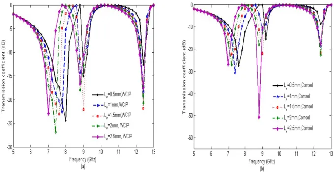
The effect of the vertical strip Lv of the proposed FSS on the resonant frequencies is shown in Figs. 6 and 7 for x-polarization and y-polarization respectively. In the x-polarization case, when Lv changes from 0.5 mm to 2.5 mm, the lowest resonant frequency is decreased from about 8 GHz to about 7GHz. The centered resonant frequency slightly decreases while the highest resonant frequencies remain constant. The results in Fig. 7 concern the y-polarization case and shows that the lowest resonant frequency decreases with the increase of Lv, while the highest one remains constant.
Fig. 6.Transmission coefficient S21 versus the operating frequency for different lengths Lv when the FSS is x-polarized. (a)WCIP results, (b) COMSOL results.
Brazilian Microwave and Optoelectronics Society-SBMO received 31 Mar 2018; for review 5 Apr 2018; accepted 22 Sept 2018 Brazilian Society of Electromagnetism-SBMag © 2018 SBMO/SBMag ISSN 2179-1074
The variation of Lv can serve as a large tuning way for the lowest resonant frequency for both polarizations as it can serve also as a fine tuning way for the centered resonant frequency in the x
polarization.
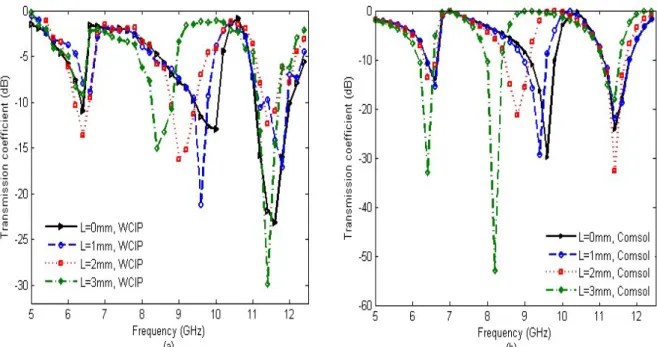
Another important parameter, which affects the resonant frequencies of the proposed FSS, is the length L of the notch. Figs. 8 and 9 show the transmission coefficient due to the increase in L for x -polarization and y-polarization respectively.
Fig. 8. Transmission coefficient S21 versus the operating frequency for different lengths L when the FSS is x-polarized. (a)WCIP results, (b) COMSOL results.
Brazilian Microwave and Optoelectronics Society-SBMO received 31 Mar 2018; for review 5 Apr 2018; accepted 22 Sept 2018 Brazilian Society of Electromagnetism-SBMag © 2018 SBMO/SBMag ISSN 2179-1074
As the values of L increase from 0 to 3 mm, the central resonant frequency decreases from about 9.8 GHz to 8.1 GHz while both the lowest and the highest resonant frequencies do not change. In the case of y-polarization source plane wave, when the height L increases the highest resonant frequency decreases, while the lowest one remains constant.
IV. BANDWIDTH ENHANCEMENT
The adjustment of different resonance frequencies can result in widening the FSS band by fusing two adjacent resonant frequencies bandwidth. In the case of Lh =12 mm and the x-polarized exciting source, the highest resonant frequency decreases and merges with the central resonant frequency resulting in only one resonant frequency as the lowest resonant frequency disappears and an improvement of the FSS bandwidth has shown in Fig. 10. The enhanced bandwidth is 6.95 GHz at -3 dB and -3.25 GHz at -10 GHz concerning the WCIP results.
Fig.10. Transmission coefficient S21 versus the operating frequency when Lh=12 mm for the x-polarized FSS.
V. RESONANT FREQUENCY ESTIMATION
Brazilian Microwave and Optoelectronics Society-SBMO received 31 Mar 2018; for review 5 Apr 2018; accepted 22 Sept 2018 Brazilian Society of Electromagnetism-SBMag © 2018 SBMO/SBMag ISSN 2179-1074
f = (1)
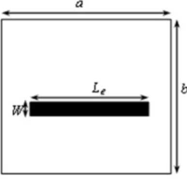
c is the speed of light in free space given by c=3x10⁸ m/s, L is the length of the metallic strip, and
ε is the effective dielectric constant of the structure and can be calculated from the equation of microstrip lines as[18]:
ε = + 1 + 12 (2)
Where W is the metallic strips width (W=2 mm), h is the thickness of the substrate taken here as h=1mm due to their availability in the laboratory. Therefore, the value of the effective dielectric constant, in this case, is given as ε =3.3425.
Fig. 11. metallic strip FSS unit cell with the effective strip’s length.
First, the resonant frequencies for different values of the FSS dimension Lh or L shown in Fig. 1 are determined by the WCIP method and the COMSOL Multiphysics software but maintaining the other FSS dimensions constant. Then, the different equivalent strips lengths called effective lengths Le are calculated using:
L = (3)
At this stage, the real metallic strips length that if manufactured gives the same result is not yet determined since it is related to the effective length Le by:
Le=Lr/k (4) Where k is a polynomial to be determined from the curve relating the complex FSS dimension Lh or L and the effective length Le calculated in (3). Thus, it can be noted as k(Lh) or k(L). Once determined, the resonant frequency of the FSS of Fig. 1is directly given by only inserting the concerned dimension Lh or L.
Brazilian Microwave and Optoelectronics Society-SBMO received 31 Mar 2018; for review 5 Apr 2018; accepted 22 Sept 2018 Brazilian Society of Electromagnetism-SBMag © 2018 SBMO/SBMag ISSN 2179-1074
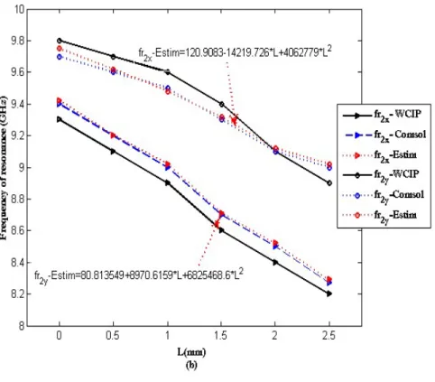
many methods for optimization like the genetic algorithm, neural network, gradient method, least square method ... In the following, the optimization with the least square method of one variable on the resonance frequencies by using the Scilab software [19] is used. Therefore, knowing the two polynomials concerning the FSS dimensions Lh and L, the resonant frequency of the FSS structure of Figs. 1 and 2 can be easily anticipated only by knowing the values of the influencing dimensions Lh and L, the dielectric without using neither the WCIP method nor the COMSOL Multiphysics or HFSS or other commercial software. The precise equation giving the FSS resonant frequency is then given by:
f _ = k(L ) (5.a)
where Lh is the varied dimension FSS from the standard FSS dimensions shown in Fig. 1 in addition to the substrate thickness h=1mm and its dielectric constant r=4.4.
f _ = k(L) (5.b)
where L is the varied dimension FSS from the standard FSS dimensions shown in Fig. 1 in addition to the substrate thickness h=1mm and its dielectric constant r=4.4, and c is the speed of light c=3x10⁸ m/s.
Brazilian Microwave and Optoelectronics Society-SBMO received 31 Mar 2018; for review 5 Apr 2018; accepted 22 Sept 2018 Brazilian Society of Electromagnetism-SBMag © 2018 SBMO/SBMag ISSN 2179-1074
Fig. 12. The five resonant frequencies with the variations of the dimensions influenced. (a) fr1x, fr3x and fr1y, (b) fr2x, and fr2y.
VI. L-NOTCHED RECTANGULAR METALLIC RING FSS EQUIVALENT STRUCTURE DETERMINATION
APPROACH
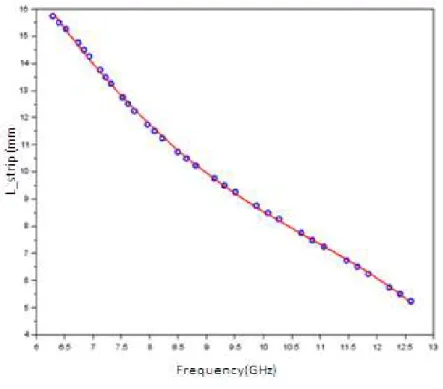
The dimensions affecting each resonant frequency of a complex metallic pattern FSS such as the notched quasi-square FSS are determined after achieving the parametric study of the structure. A deep comprehension of the FSS behavior leads to a determination of a simple equivalent circuit based on series LC components branches which are not all the time possible for all FSS structures. To overcome this drawback, equivalent FSS structures based on non-coupled parallel metallic strips are introduced which necessitate the presentation of an approximate approach determining the real or the physical length Lr, Fig. 1, of the metallic strip FSS to end with an FSS having the desired resonant frequency. First, the curve describing the relationship between the resonant frequency and the actual length of the strip Lr is plotted in Fig. 13, by recording the resonant frequency calculated by the WCIP method for different strip lengths Lr varying from 5.25 mm until 15.75 mm with a step equal to 0.25 mm, so that to cover the interval of Lr values possible by the standard metallic strip FSS being W=1 mm, the substrate dielectric constant εr = 4.4, the substrate thickness h = 1 mm, the dimensions of the basic unit cell are a x b = 20 mm x 20 mm as shown in Fig. 11.
Brazilian Microwave and Optoelectronics Society-SBMO received 31 Mar 2018; for review 5 Apr 2018; accepted 22 Sept 2018 Brazilian Society of Electromagnetism-SBMag © 2018 SBMO/SBMag ISSN 2179-1074
obtained by the WCIP method for a given strip’s length Lr. The red curve is obtained by an interpolation process of the WCIP results.
Fig. 13.Real metallic strip length of the FSS as a function of its resonant frequency.
From Fig. 13 the length Lr can be determined for any value of the desired frequency varying from 6.29 to 12.60 GHz. To validate the approximate proposed approach, the measured resonant frequencies of three proposed FSS are used.
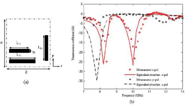
The first structure presents the unit cell of the notched rectangular metallic ring FSS shown in Fig. 3, where the resonant frequencies given by the system of measurement and considered as desired resonant frequencies for the presented approach are 8.4 GHz and 10.1 GHz when the incident wave is x-polarized and 7.8 GHz when the incident wave is y-polarized. An FSS structure equivalent to the structure of Fig. 3 and based on two non-coupled metallic strips according to x -polarization with lengths L1x and L2x, and a single metallic strip according to y with length L1y is shown in Fig. 14.a.
The resonant frequencies given by the measurements and corresponding to the structure of Fig. 3 are replaced in Fig.13as desired resonant frequencies giving the real lengths of the strips as L1x= 10.98 mm, L2x= 8.41 mm, L1y= 7.8 mm. The basic FSS unit cell has dimensions of a=20 mm and b=20 mm, substrate dielectric constant of r=4.4 and a thickness of h=1 mm.
The resonant frequencies obtained by the WCIP method when characterizing the equivalent FSS resulting from the presented synthesis approach are 8.2 GHz and 10 GHz when the incident wave is
Brazilian Microwave and Optoelectronics Society-SBMO received 31 Mar 2018; for review 5 Apr 2018; accepted 22 Sept 2018 Brazilian Society of Electromagnetism-SBMag © 2018 SBMO/SBMag ISSN 2179-1074
proposed equivalent FSS structure of Fig. 14.a is 2.38% and 0.99% respectively in x-polarization and 0 % iny-polarization.
Fig. 14.(a) FSS Structure equivalent to the notched quasi-square FSS structure, (b) Simulated and measured transmission coefficient versus the operating frequency for the x-polarized source and the y-polarized source.
The same approach’s steps are repeated to find the equivalent FSS structures of the open notched quasi-square metallic ring FSS proposed in [9] and shown in Fig. 15. The manufactured FSS are printed on a fiber glass (FR-4) substrate with dielectric constant r=4.4 and a thickness of h=1 mm [9].
Fig.15. The open notched quasi-square metallic ring FSS with unit cell geometry [9].
Brazilian Microwave and Optoelectronics Society-SBMO received 31 Mar 2018; for review 5 Apr 2018; accepted 22 Sept 2018 Brazilian Society of Electromagnetism-SBMag © 2018 SBMO/SBMag ISSN 2179-1074
TABLE I:EQUIVALENT STRUCTURES STRIPS LENGTHS OF THE OPEN NOTCHED QUASI SQUARE METALLIC RING FSS WITH
LH=9.5MM.
Measured resonant frequency (GHz) of the open notched quasi square metallic
ring FSS
real metallic strip length Lr(mm)
Equivalent metallic strips FSS resonant frequency (GHz)
Error %
x-polarized source fr1x=9.1
fr2x=9.9 fr3x=11.7
L1x=9.6 L2x=8.67 L3x=6.49
fr1x=9 fr2x=10.2 fr3x=11.6
1.10 3 0.86
y-polarized source fr1y=6.7 L1y=14.76 fr1y=6.6 1.49
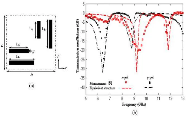
The resulting equivalent FSS structure to the structure presented in Fig. 15 is based on three uncoupled parallel metallic strips, according to x-polarization with lengths L1x,L2xand L3xand a single metallic strip according to y polarization as shown in Fig.16.a.
When Lh=11.5 mm, the parallel metallic strips FSS structure equivalent to the open notched quasi-square metallic ring FSS of Fig. 15 is shown in Fig. 17.a. This structure is based on two metallic strips according to x-polarization with lengths L1x and L2x and two metallic strips according to y -polarization with length L1y and L2y .
Table II summarizes the different obtained results for the strips lengths corresponding to the measured frequencies of the open notched quasi-square metallic ring FSS show in Fig.15 for Lh=11.5mm.
TABLE II:EQUIVALENT STRUCTURES STRIPS LENGTHS OF THE OPEN NOTCHED QUASI-SQUARE METALLIC RING FSS WITH
LH=11.5MM.
Measured resonant frequency (GHz) of the open notched quasi square metallic
ring FSS
real metallic strip length Lr (mm)
Equivalent metallic strips FSS resonant frequency (GHz)
Error %
x-polarized source fr1x=8.8 fr2x=11.7
L1x=10.28 L2x=6.49
fr1xe=8.8 fr2xe=11.6
0 0.86
y-polarized source fr1y=6.5 fr2y=8.8
L1y=15.3 L2y=10.28
fr1ye=6.4 fr1ye=8.8
1.54 0
Brazilian Microwave and Optoelectronics Society-SBMO received 31 Mar 2018; for review 5 Apr 2018; accepted 22 Sept 2018 Brazilian Society of Electromagnetism-SBMag © 2018 SBMO/SBMag ISSN 2179-1074
Fig. 16. (a) Equivalent structure, (b) Simulated and measured transmission coefficient versus the operating frequency for the x-polarized source and the y-polarized source for the structure with Lh=9.5 mm.
Brazilian Microwave and Optoelectronics Society-SBMO received 31 Mar 2018; for review 5 Apr 2018; accepted 22 Sept 2018 Brazilian Society of Electromagnetism-SBMag © 2018 SBMO/SBMag ISSN 2179-1074
VII. THE L-NOTCHED RECTANGULAR METALLIC RING FSS ABACUSES
When the applications are restricted to a specific FSS pattern as that shown in Fig. 1, abacus can provide rapid precise results without a need to use neither software nor experimental measurements.
In this part abacuses are proposed and used to extract the resonant frequencies of the L- notched rectangular metallic ring FSS structure but without doing any simulation.
So according to the parametric study of the FSS of Fig. 2, the resonance frequencies fr1x, fr3x and fr1ydepends on the length Lh while fr2x and fr2y are varied according to L.
Figs.18 and 19 show the effect of increasing the lengths Lh and L on L-notched rectangular metallic ring FSS resonant frequencies respectively.
Fig. 18. The resonant frequencies versus the length Lh with L=2mm and Lv=4mm.
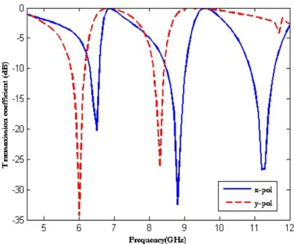
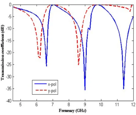
Figs. 18 and 19 can be used as abacus for the choice of the dimensions of the L- notched rectangular metallic ring FSS of Fig. 2providing desired resonant frequencies. According to Fig.18, the values of the resonant frequencies fr1x, fr2x, fr3x, fr1y and fr2yfor a fixed value of the length Lh=4.8 mm are respectively: 6.5 GHz, 9 GHz, 11.3 GHz, 6 GHz et 8.2 GHz.
Brazilian Microwave and Optoelectronics Society-SBMO received 31 Mar 2018; for review 5 Apr 2018; accepted 22 Sept 2018 Brazilian Society of Electromagnetism-SBMag © 2018 SBMO/SBMag ISSN 2179-1074
Fig. 19.The resonant frequencies versus the length L with Lh= 4.5 mm and Lv=4 mm.
Fig. 20. Transmission coefficient versus frequency for Lh=4.8 mm L=2 mm and Lv=4 mm.
Brazilian Microwave and Optoelectronics Society-SBMO received 31 Mar 2018; for review 5 Apr 2018; accepted 22 Sept 2018 Brazilian Society of Electromagnetism-SBMag © 2018 SBMO/SBMag ISSN 2179-1074
Fig. 21. Transmission coefficient versus frequency for L=1.7mm,Lh=4.5mm and Lv=4mm.
VIII. CONCLUSION
In this paper, the L- notched rectangular metallic ring FSS is analyzed using WCIP method. The proposed FSS presents a frequency behavior that may be suitable in the design of multiband structures where the FSS can be used simultaneously for dual and three-band applications when the two perpendicular polarizations are considered. One FSS has been fabricated and characterized. The FSS resonant frequencies can be adjusted by changing the dimensions of the FSS determined by the parametric study. To determine the approximate equations of the different FSS resonant frequencies an approximate procedure is presented. In complex pattern FSS such as the open notched quasi-square metallic ring FSS the determination of an equivalent circuit based on resonant LC circuit offering a complete FSS behavior comprehension is quite difficult. Thus the approximate procedure is extended to determine the complex patterns FSS equivalent structures based on non-coupled parallel metallic strips that can replace the complex pattern FSS for given resonant frequencies. When the applications are limited to a specific FSS such as L- notched rectangular metallic ring FSS due to its availability in terms of cost and manufacturing, abacuses can be used to save time without a need to software. Two abacuses are plot and verified.
REFERENCES
[1] K. Sarabandi and N. Behdad, “A Frequency Selective Surface With Miniaturized Elements,” IEEE Trans.
Antennas Propag, vol. 55, no. 5, pp. 1239–1245, 2007.
Brazilian Microwave and Optoelectronics Society-SBMO received 31 Mar 2018; for review 5 Apr 2018; accepted 22 Sept 2018 Brazilian Society of Electromagnetism-SBMag © 2018 SBMO/SBMag ISSN 2179-1074
single- and dual-band applications together with absorber and sensor configurations,” IET Microwaves, Antennas
Propag., vol. 10, no. 3, pp. 293–300, 2016.
[3] M. Titaouine, N. Raveu, A. G. Neto, and H. Baudrand, “dual-band and enhanced band fss characterization using the WCIP method,” Microw. Opt. Technol. Lett, vol. 52, no. 4, pp. 836–839, 2010.
[4] J. Lee, M. Yoo, S. Member, and S. Lim, “A Study of Ultra-Thin Single Layer Frequency Selective Surface Microwave Absorbers With Three Different Bandwidths Using Double Resonance,” IEEE Trans. Antennas Propag., vol. 63, no. 1, pp. 221–230, 2015.
[5] A. L. P. S. Campos, F. C. G. da S. Segundo, R. H. C. Manicoba, and A. G. N. and A. G. D’Assuncao, “A Simple Fractal Geometry to Design Multi-Band Frequency Selective Surfaces,” Microw. Opt. Technol. Lett, vol.54, no.10, pp 2321-2325, 2012.
[6] M. T. Letters, A. L. Pereira, S. Campos, U. Federal, R. Grande, U. Federal, R. Grande, R. Hebraico, C. Mani, and U. Estadual, “A Comparative Study of Two Numerical Techniques To Analyze Double Screen Frequency Selective Surface,” Microw. Opt. Technol. Lett, vol.55, no.9, pp 2206-2209, 2013.
[7] Y. Li, L. Li, Y. Zhang, and C. Zhao, “Design and synthesis of multilayer frequency selective surface based on antenna-filter-antenna using minkowski fractal structures,” IEEE Trans. Antennas Propag., vol. 63, no. 1, pp. 133–141, 2015.
[8] D. H. Kim and J. I. Choi, “Design of a multiband frequency selective surface,” ETRI .J, vol. 28, no. 4, pp. 506– 508, 2006.
[9] I. Adoui, M. Titaouine, H. Choutri, A. Djouimaa, T. Rolim De Sousa, A.G. Neto and Henri Baudrand, “Characterization of novel open notched quasi-square metallic ring FSS using WCIP method,” Microw. Opt.
Technol. Lett., vol. 58, no. 9, pp. 2071–2075, 2016.
[10] J. A. Bossard, D. H. Werner, T. S. Mayer, J. A. Smith, Y. U. Tang, R. P. Drupp, and L. Li, “The Design and Fabrication of Planar Multiband Metallodielectric Frequency Selective Surfaces for Infrared Applications,” IEEE
Trans. Antennas Propag., vol. 54, no. 4, pp. 1265–1276, 2006.
[11] D. Kim, J. Yeo, and J. Choi, “Compact Spatial Triple-Band-Stop Filter for Cellular / PCS / IMT-2000 Systems,”
ETRI J., vol. 30, no. 5, pp. 735–737, 2008
[12] M. Titaouine, N. Raveu, A. G. Neto, and H. Baudrand, “Electromagnetic Modeling of Quasi-Square Open Metallic Ring Frequency Selective Surface Using Wave Concept Iterative Procedure,” ETRI J., vol. 31, no. 1, pp. 77–79, 2009.
[13] I. Adoui, M. Titaouine, A.Djouimaa, H. Choutri and H. Baudrand, “WCIP Method Applied to Modeling a Modified Rectangular Metallic Ring FSS for Multiband Applications”, 7th seminar on Detection Systems:
Architectures and Technologies (DAT'2017), 2017
[14] A. Djouimaa, M. Titaouine, I. Adoui, T. Rolim De Sousa, A. G. Neto and Henri Baudrand., "Tunable FSS simulation using WCIP method for multiband and dual polarized application", Radioelectronics and
Communications Systems, vol. 60, no. 3, pp. 106–112, 2017.
[15] M. Aouissi, M. Titaouine, T. Rolim De Sousa, I. Adoui, A. G. Neto and Henri Baudrand, "Analysis of a joined split-ring FSS structure characterized by three resonant frequencies and a tuned enhanced band using the WCIP method", Turkish Journal of Electrical Engineering & Computer Sciences, vol. 25, pp. 288- 2896, 2017.
[16] R. Saidi, M. Titaouine, A. Djouimaa, T. R. Sousa, A. G. Neto, K. Bencherif and H. Baudrand, “Characterization of Switchable Rectangular Ring FSS with Non Coupled Parallel Metallic Strips for Multi Band and Dual Polarized Applications Using WCIP Method”, Journal of Microwave, Optoelectronics and Electromagnetic
Applications, vol. 17, no. 1, pp. 102-120, March 2018.
[17] A. G. Neto, J. Costa, J. N. De Carvalho, A. Nascimento, C. B. De Aguiar, and D. F. Mamedes, “Analysis of Frequency Selective Surface with U-Shaped Geometry,” Journal of Microwave, Optoelectronics and
Brazilian Microwave and Optoelectronics Society-SBMO received 31 Mar 2018; for review 5 Apr 2018; accepted 22 Sept 2018 Brazilian Society of Electromagnetism-SBMag © 2018 SBMO/SBMag ISSN 2179-1074 [18] M. O. L. Matekovits, G. C. Vietti Colomè, “Effect of transverse periodicity on the value of the effective dielectric