Abstract— In this paper, a rectangular metallic ring FSS (Frequency Selective
Surfaces) with parallel metallic strips for multi band applications are characterized by the WCIP (Wave Concept Iterative Procedure) method. The proposed FSS structures are made of metallic elements that are simultaneously independent in the spatial domain and uncoupled in the spectral domain. Thus the FSS multiband behavior can be achieved only by a building process based on independent metallic elements in both domains. The resonant characteristics of the proposed FSS are determined. The structure shows three resonant frequencies when the incident wave is x-polarized and three resonant frequencies when the source is polarized in the orthogonal direction. A variation in the length of the strips and the rectangular ring allows a fine tuning in the FSS resonant frequencies to give raise to tuned bandwidths. The suppression of a resonant frequency can be insured either by the elimination of the responsible metallic strip or by the insertion of a PIN diode switch. Three FSS structures are manufactured and characterized. The FSS bandwidth can be enhanced in both perpendicular FSS exciting source directions by only varying the strips lengths and the ring dimensions to the corresponding resonant frequencies. A good agreement is obtained when the WCIP results are compared with the simulations of COMSOL Multiphysics software and experiment.
Index Terms— WCIP method, FSS structures, transmission coefficient, metallic strips, rectangular ring, resonant frequency, PIN diode, enhanced bandwidth.
Characterization of Switchable Rectangular
Ring FSS with Non Coupled Parallel Metallic
Strips for Multi Band and Dual Polarized
Applications Using WCIP Method
R. Saidi, 1 M. Titaouine, 1, 2 A. Djouimaa, 1
1
Department of Electronics, Faculty of Technology, University of Batna 2, Batna 05000, Algeria
2
Laboratory of Materials and Electronic Systems LMSE, Faculty of Sciences and Technology University of Bordj Bou Arreridj, University, El Anasseur 34625, Algeria
[email protected], [email protected],
T. R. Sousa, 3 A. Gomes Neto, 3
3
Group of Telecommunications and AppliedElectromagnetism,
GTEMA, Federal Institute of Education Science and Technology of Paraiba, IFPB, Av. 1 de Maio, 720, Joao Pessoa, PB, CEP 58015-430, Brazil
[email protected], [email protected]
K. Bencherif, 1
1
Department of Electronics, Faculty of Technology, University of Batna 2, Batna 05000, Algeria
H. Baudrand, 4
4
University of Toulouse; INPT, UPS; LAPLACE; ENSEEIHT, 2 Rue Charles Camichel, Toulouse Cedex 7, BP 7122, F-31071, France
Brazilian Microwave and Optoelectronics Society-SBMO received 08 Sep 2017; for review 08 Sep 2017; accepted 15 Mar 2018 © 2018 SBMO/SBMag ISSN
2179-I. INTRODUCTION
Along the decades, the increased demand for telecommunication systems services, due to the
technological progress encouraged the development of new frequency selective surfaces having
multiband applications and smaller sizes [1], [2]. The applications of frequency selective surfaces
(FSS) are varied; in the microwave the FSS are exploited to make a reflector antenna more efficient,
another application in this wavelength range is the radome. In the far-infrared region, periodic screens
are used as polarizers, beam splitters, as well as mirrors for improving the pumping efficiency in
molecular lasers [3], [4].
Many previous works have presented FSSs for multi-band and dual-polarization applications. In
concentric rectangular rings FSS the insertion of one more ring results in the addition of one resonant
frequency in both perpendicular directions. To decrease the metallic surface of the FSS maintaining
the multi band and dual polarization characteristics the quasi-rectangular open-rings is introduced [5],
[6], [7], [8], [9]. In the U-shaped FSS the two resonant are controlled by the strips lengths [5]. To
increase the number of resonances without altering the FSS interface another FSS layer is added to
end with a double layered FSS structure [10], [11]. Theses FSS structures suffers from being not
under the total control of the users since changing one or many FSS metallic elements dimensions at a
time leads to a non prior known frequency response unless a deep parametric study is done.
Moreover, with these FSS it is not possible to build the desired frequency response in all the cases.
Thus an equivalent circuit capable of modeling these FSS for all the cases is hard to determine.
To overcome the previous FSS drawbacks, in this paper the presented FSS structure is made of
parallel non coupled metallic strips with one rectangular metallic ring acting as a multi-band and a
dual polarized filter with three resonant frequencies for an x-polarized source and three resonant
frequenciesfor a y-polarized source. The proposed structure is composed of uncoupled metallic strips
in such a way that a resonant frequency is added (or suppressed) from the FSS frequency response by
only adding (or suppressing) its resonant frequency responsible strip or ring. Hence this independence
of the metallic elements in the spatial domain leads to the metallic elements behaviors independence
in the frequency domain. Many simulations have been simulated by the Comsol Multiphysics
software, HFFS software, and the WCIP method to end with the FSS final arrangement with
uncoupled metallic elements allowing building the FSS frequency response from individual metallic
elements frequency responses in two polarizations with the same facilities of the spatial domain.
In this paper, a rectangular metallic ring FSS with non coupled parallel metallic strips for multi band
applications is proposed. The presented FSS shows three resonant frequencies at about 6 GHz, 8.25
GHz and 10.5 GHz when the incident wave is x-polarized and three resonant frequencies at about 6
proposed structures are characterized by the WCIP (Wave Concept Iterative Procedure) method,
COMSOL Multiphysics and measurements. In the proposed FSS structure each resonant frequency
can be deleted by only eliminating the corresponding metallic strip. For more flexible FSS selectivity
and electronically controlled FSS a PIN diode switch is inserted at the center of the strip to bring the
corresponding resonant frequency higher so that it is seen as eliminated. Moreover, the presented FSS
bandwidth can be enhanced by independently and simultaneously varying the strips length and the
ring dimensions to the appropriate values.
The WCIP method (Wave Concept Iterative Procedure) gets its originality from its ease of
implementation since it is based on two essential equations. The former is defined in the spatial
domain and it is a description of the interface using the boundary conditions. Whereas the letter is
described in the modal domain and it summarizes the reflection of the diffracted waves getting out of
the interface from the modes closing impedances due to the closing conditions. The WCIP speed is
obtained from the systematic use of the fast modal transform pair FMT/FMT-1 [6] integrating in its
procedure the two dimensional fast Fourier transform pair FFT/FFT-1.
The WCIP method is used for obtaining simulation results of the single interface multilayer FSS [12],
[13]. Three proposed FSS structures are manufactured and characterized. WICIP results are compared
to results simulated by COMSOL Multiphysics 4.3v software package and experimental
measurements and a good agreement is recorded.
II. WCIP FORMULATION
The WCIP method is based on the transverse-formulation and information obtained at the interfaces
[14]. Multiple reflection process is started using the initial conditions and stopped once convergence
is reached. The diffraction operator Ŝ and the reflection operator Γ̂ relate the incident and diffracted
waves in the spatial and spectral domain respectively and govern the iterative procedure [14]. In the
WCIP method, the FSS analysis is reduced to that of the unit cell. Fig. 1.a shows an FSS with
arbitrary shape excited with a normal incident plane wave along the negative z direction. The dashed
Brazilian Microwave and Optoelectronics Society-SBMO received 08 Sep 2017; for review 08 Sep 2017; accepted 15 Mar 2018 © 2018 SBMO/SBMag ISSN
2179-The incident and the reflected waves can be obtained from the transverse electric and magnetic
fields as [15]-[18]:
A⃗⃗ i= 1
2√Z0i(E⃗⃗ Ti+ Z0i J i) (1)
B⃗⃗ i= 1
2√Z0i(E⃗⃗ Ti− Z0i J i) (2)
Z
0i indicates the characteristic impedance of medium 1 or medium 2 [14].The diffracted waves B⃗⃗ i(k) at the kth iteration are obtained from the incident waves A⃗⃗ (k)i by [6]:
B⃗⃗ i(k)= ŜΩA⃗⃗ (k)i (3)
ŜΩis the diffraction operator at the interface Ω containing the FSS circuit. It depends on the boundary conditions of each domain and the geometry of the structure. The diffraction phenomena is
seen in the modal domain and it takes place once one incident wave strikes the interface and as a
result an infinity of TE (Transverse Electric) and TM (Transverse Magnetic) modes appears due to the
presence of a metal-dielectric discontinuity. Hence equation (3) is considered as a dynamic equation
since if the FSS structure pattern is changed this equation has to be also changed due to the presence
of the diffraction operator ŜΩ depending on the physical interface containing the electric circuit.
Once the diffracted waves appear, they are reflected by the modes closing impedances at the closing
wall representing the two ends of the hypothetical rectangular periodic waveguide containing the FSS
unit cell. The incident waves A⃗⃗ (k+1)i of the (k+1)th iteration can be calculated by [6]:
A⃗⃗ (k+1)i = Γ̂iBi(k)+ A⃗⃗ 0 (4)
Where Γ̂iBi(k) represents the reflected waves with Γ̂ibeing the reflection operator defined in the
modal domain.
The FMT/FMT-1 transform pair given in [6] allows the transition between the spatial domain and the
modal domain.
Equation (4) is structure independent and it is seen as a static equation. Hence the only parameter
that depends on the structure is the diffraction operator. Thus when changing the structure all the
algorithm parameters remain the same except the diffraction operator giving to the WCIP method
another potential favor in studying planar circuits as compared to other methods such as the method of
moments where if the structure is changed all the parameters constituting its algorithm have to
A multiple reflection procedure is started using the initial conditions and stopped once the
convergence is reached. Thus, the tangential electric and magnetic fields can be calculated as [12],
[13], [19]-[21]:
E⃗⃗
i= √Z
0i(A
⃗⃗⃗ + B⃗⃗
i i)
(5)
J i= (1/√Z0i)(A⃗⃗ i− B⃗⃗ i) (6)
The WCIP method adopted in this paper doesn’t account for the losses in the FSS structures. The
only source of losses is the limited number of used modes due to the meshed interface. Theoretically
the convergence cannot be obtained at the resonance since the waves at this state are reflected back
and forth by the interface and the closing walls as if they are imprisoned. But the losses caused by the
limitation in the number of used TE and TM modes in the analysis forces the convergence to exist at
structure resonance. The use of the medium impedance Z0ican be replaced by any impedance Z0 [6]
with Z01= Z02= Z0 . It is initially used as medium impedance to provide some physical sight on its
value.
III. THE PARALLEL METALLIC STRIPS WITH RECTANGULAR METALLIC RING FSS
DESIGN
The proposed structure is a parallel non coupled metallic strips with one rectangular metallic ring,
shown in Fig. 2(a). The manufactured FSS of 20 cm × 20 cm size is printed on a fiber glass (FR-4)
substrate with dielectric constant of r=4.4 and a thickness of h=1.5 mm. The remaining FSS
dimensions shown in Fig. 2(b) representing the FSS unit cell are: L1 = 10.45mm, L2 = 7.27mm, L3 =
11.36mm, L4 = 9.45mm, L5 =7.27mm, W1 = W2 = W4 = W5 = 1mm, W=1mm and W3 = 11.81mm.
Fig. 2. The rectangular metallic ring FSS with parallel metallic strips: (a) Realized FSS with an array of 10 × 10 unit cells and (b) FSS unit cell geometry.
x y
b a
L1
L2
L3
L4
L5
W3
W4
W5
W2
W1
W Dielectric domain
Metallic domain
Brazilian Microwave and Optoelectronics Society-SBMO received 08 Sep 2017; for review 08 Sep 2017; accepted 15 Mar 2018 © 2018 SBMO/SBMag ISSN
2179-IV. Results and analysis
To validate the implemented WCIP method results for no need to more improvement to accelerate
convergence for the used grid and stopping iterative procedure in addition to mastering Comsol
Multiphysics for planar FSS problems, the scattering parameters of the structure shown in figure 2 are
obtained by the WCIP method. A grid of 100×100 pixels is used to describe the FSS interface and the
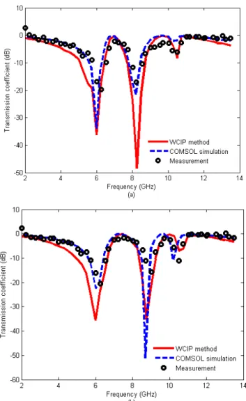
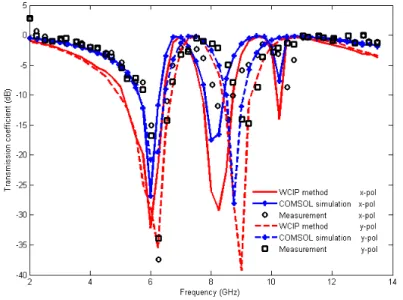
iterative process is stopped after 350 iterations. As shown in Fig .3(a) the resonant frequencies are
about 6 GHz, 8.25 GHz and 10.5 GHz when the incident wave is x-polarized and 6 GHz, 8.75 GHz
and 10.5 GHz when the source is y-polarized as shown in the Fig. 3(b).
Fig. 3. Simulated and measured transmission coefficient versus the operating frequency for: (a) The x-polarized source (b) The y-polarized source
In the next part and using the implemented WCIP method, the characteristic of the presented FSS as
being composed of uncoupled FSS elements is independently verified for each metallic strip. It is
shown that the variation of one strip length maintaining the remaining FSS elements dimensions
A. Variation of the strip length L1
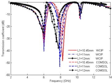
The results concerning the transmission coefficients for different values of the length of the strip L1
of Fig. 1(b) obtained by the WCIP method and the Comsol software are given in Fig. 4.
Fig. 4. Transmission coefficient versus frequency for different values of L1 for an x-polarized source WCIP results and
COMSOL results.
Observing figure 4, it is noted that when using the WCIP method the strip length L1 increases its
corresponding resonant frequency decreases from 8.25 GHz to 7.75 GHz for values of L1 equal to
10.45mm and 12 mm respectively in the x polarization. The corresponding resonant frequencies using
Comsol multiphysics software decrement from 8.2 GHz 7.5 GHz. The relative error between the
WCIP method results and Comsol Multiphysics software in determining the resonant frequencies are
0.61%, 1.26% and 3.33% when L1 equals to 10.45mm, 11mm and 12mm respectively. The principle
characteristic of the presented FSS structure is shown by the fact that the two resonant frequencies
recorded at 6GHz and 10.5GHz are not altered since the strips and the ring are not coupled.
B. Variation of the strip length L2
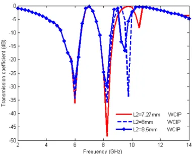
The transmission coefficients of the structure as a function of the operating frequency,
Brazilian Microwave and Optoelectronics Society-SBMO received 08 Sep 2017; for review 08 Sep 2017; accepted 15 Mar 2018 © 2018 SBMO/SBMag ISSN
2179-Fig. 5. The transmission coefficient versus the frequency for L2=7.27 mm until 8.5 mm for an x-polarized source.
When the length L2 increases the resonance frequency decreases, giving a value of 10.5 GHz for L2
equal to 7.27 mm and 9.5 GHz for a value of L2 equal to 7 8.5 mm in the x polarization.
In the y polarization the effect of varying the lengths L1 and L2 on the resonant frequencies is not
observed.
C. Variation of the strip length L4
As shown in Fig. 6, the resonant frequency of the structure is decreasing when L4 is increasing,
taking values of 8.75GHz for L4=9.45 mm, 8.5GHz for L4=10.25mm and 8GHz for L4=11 mm.
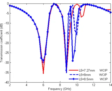
D.Variation of the strip length L5
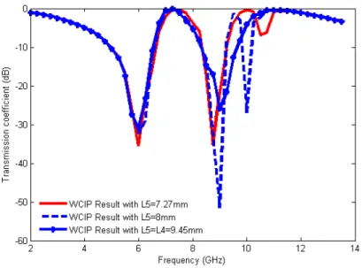
Fig. 7. The transmission coefficient versus the frequency for L5=7.27 mm until 8.5 mm for a y-polarized source.
The transmission coefficients as a function of the operating frequency, corresponding to different
values of L5 are shown in Fig. 7. When the length L5 increases from 7.27mm, to 8mmm until 8.5mm
the resonance frequency decreases, from 10.5 GHz until 9.75 GHz.
In the case of an x-polarized source of excitation, the effect of varying L4 and L5 is not recorded.
Hence, the presented FSS structure is based on non coupled parallel metallic strips. As a result the
proposed FSS resonant frquencies can be independently adjusted by only varying the corresponding
strips lengths.
E. Switchable FSS
Another way of confirming that a strip is uncoupled with the remaining structure elements is by
physically eliminating it without affecting the remaining FSS elements frequency response. To
confirm the non coupling of the strip L5 and its presence lead to inserting the highest resonant
frequency 10.5GHz of the structure in the y polarization, it is definitively eliminated, taking the
remaining dimensions equal to: L1=10.58mm, L2=7.50mm, L3=11.32mm, L4=9.70mm, W3=11.82mm
Brazilian Microwave and Optoelectronics Society-SBMO received 08 Sep 2017; for review 08 Sep 2017; accepted 15 Mar 2018 © 2018 SBMO/SBMag ISSN
2179-Fig. 8. The rectangular metallic ring FSS with parallel metallic strips:
(a) Realized FSS with an array of 10 × 10 unit cells and (b) FSS unit cell geometry without L5.
Fig. 9 presents the transmission power of the structure of Fig. 8. It is clear that the highest resonant
frequency at 10.5GHz is eliminated when the structure is y polarized while the other resonant
frequencies are maintained fixe in both polarization x and y.
Fig. 9. Simulated and measured results for the transmitted power of the parallel metallic strips
with rectangular metallic ring FSS versus frequency according to the x and y polarizations.
b
x y
a
L1
L2
L3
L4
W
W W
W
W Dielectric domain
Metallic domain
To take benefit of both cases of the presence of the highest resonant frequency and its elimination a
switchable FSS is necessary. The strip elimination is achieved by pushing its corresponding resonance
out of the operating frequency window ranging from 2GHz to 14 GHz. Even though it is not
physically suppressed its behavior is eliminated. Thus switchable FSS consists in the addition or the
elimination of a metallic strip via the insertion of an ideal ON-OFF states switch in the center of a
strip to bring higher its corresponding resonant frequency, 2fr. The ideal switch is replaced by a gap of
dimensions 1mm×1mm as shown in Fig. 10 where the switch is inserted in the center of the strip L2.
The structure is fabricated and characterized.
Fig.10. The rectangular metallic ring FSS with parallel metallic strips:
(a) Realized FSS with an array of 10 × 10 unit cells and (b) FSS unit cell geometry with a gap on the strip length L2.
The Transmission power of the structure of Fig. 10 is shown in Fig. 11. It shows only two
resonances at about 6.25 GHz, and 8.25 GHz according to the x polarization with a clear elimination
of the third resonant frequency and two resonances at about 6GHz, and 9 GHz according to the y
polarization.
b
x y
a
L1
L2
L3
L4
W3
W4
W2
W1
W Dielectric domain
Metallic domain
Brazilian Microwave and Optoelectronics Society-SBMO received 08 Sep 2017; for review 08 Sep 2017; accepted 15 Mar 2018 © 2018 SBMO/SBMag ISSN
2179-Fig. 11. Simulated and measured transmission coefficient versus the frequency for the x and y polarizations.
When PIN diodes are used to operate as RF/microwaves switches, they are modeled as a simple
resistance in the forward biasing case and as a resistance in parallel with a capacitor for the reverse
biasing diode case. To account for PIN diodes insertion in the WCIP method an impedance diffraction
operator is first determined by the use of the diodes equivalent impedance as surface impedance in the
domain occupied by the diodes as in [20]. Thus the diode FSS structures consist of four domains with
the addition of the diodes domain. In fig.12 the metallic strip FSS with a diode reversely biased at
-30V and with a diode replaced by a gap the transmission coefficient of is shown representing WCIP
results and HFSS results. The diode is reversely polarized at -30V and it is modeled as a resistance of
4k in parallel with a capacitor of 0.052 pF and it can be modeled as a resistance of 1 when it is
forward biased [22]. The transmission coefficient of the metallic strip FSS with a diode inserted at the
Fig. 12. Simulated transmission coefficient versus the frequency for the x-polarized source exciting a metallic strip FSS with a diode reversely biased at the strip center.
Fig. 13. Simulated transmission coefficient versus the frequency for the x-polarized source exciting a metallic strip FSS with a diode forward biased at the strip center.
Figs. 12 and 13 show a good agreement between an ideal ON/OFF switch and a PIN diode switch.
Thus the presented measurement of fig. 11 when a gap is inserted can be used to confirm the OFF
state PIN diodes presence since the metallic strips in the parallel metallic strip FSS presented are not
coupled.
2 4 6 8 10 12 14
-18 -16 -14 -12 -10 -8 -6 -4 -2 0 T ra n s m is s io n c o e ff ic ie n t (d B ) Frequency (GHz) WCIP Result with Diode OFF -30V HFSS Result with Diode OFF -30V HFSS Result with gap
a
L
b
W
Brazilian Microwave and Optoelectronics Society-SBMO received 08 Sep 2017; for review 08 Sep 2017; accepted 15 Mar 2018 © 2018 SBMO/SBMag ISSN
2179-V. BANDWIDTH ENHANCEMENT AND TUNABILITY
The principal advantage of the presented FSS based on non coupled parallel metallic strips in easily
enhancing the FSS bandwidth can arise when adjusting independently each of the strips length to give
rise to the desired resonant frequency so that the resulting transmission power posses the desired
enhanced bandwidth. In addition the rectangular metallic ring dimensions can also used to bring its
corresponding resonant frequency to improve the FSS bandwidth. The FSS of fig. 2b is taken as a
reference structure to design an enhanced band FSS. At -3dB of the transmission power it has
rejecting bandwidths of 3.35GHz, 1.76 GHz and 0.46 GHz centered at resonant frequencies
respectively when the source is x polarized. In the case of the y polarized source the rejecting
bandwidths are 3.70 GHz, 1.65 GHz and 0.57 GHz. At -10dB of the transmission power two rejecting
bands exist in both source polarizations with bandwidths of 1.37 GHz, 1.021GHz for the x polarized
source and 1.71 GHz and 0.92 GHz when the source is y polarized. Fig. 14 shows the variation of the
transmission coefficient as a function of the operating frequency for different values of the metallic
strip of length L2 resulting in decreasing the FSS higher resonant frequency. For L2 equals to
10.45mm, its corresponding resonant frequency intervenes to enhance the bandwidth situated at
8.25GHz for the x polarized FSS. Thus bandwidth presented initially at this frequency is enlarged to
2.44 GHz at -3dB and 1.42 GHz at -10dB to result to a band enhancement of 38.64% at -3dB and
39.08% at -10dB. Another mean of enhancing the improved band at 8.25GHz is a decrease in the
metallic ring dimension L3 to result in moving higher its corresponding resonant frequency as shown
in fig. 15. When L3 takes the value of 5mm its corresponding bandwidth overlaps with the initial
rejecting bandwidth situated at 8.25GHz to result in enhancing again the rejecting bandwidth situated
at 8.25GHz to 4.10 GHz at -3dB and 1.65 GHz at -10dB. Thus a bandwidth improvement of 123.86%
at -3dB and 61.60% at -10dB as compared to the initial FSS rejecting bandwidth occurring at
Fig. 14. Transmission coefficient for different increasing values of L2 for x-Polarization
Fig. 15. Transmission coefficient for different decreases values of L3 and fixed L2=10.45mm for y-Polarization
To improve the FSS bandwidth when it is excited with a y polarized source, the strip length L5 is
increased to 9.45 mm to take the same value of L4as shown in fig. 16. A bandwidth of 2.40 GHz at
-3dB and 1.3 GHz at -10dB is observed. Thus the rejecting bandwidth occurring at a resonant
frequency of at 8.25GHz is enhanced with 45.45% at -3dB and 41.3% at -10dB occurs. The obtained y
Brazilian Microwave and Optoelectronics Society-SBMO received 08 Sep 2017; for review 08 Sep 2017; accepted 15 Mar 2018 © 2018 SBMO/SBMag ISSN
2179-shown in fig. 17. When W3 decreases to 4mm the resulting rejecting bandwidth situated at 8.25GHz is
improved to 3.67GHz at -3dB without being altered for -10dB reference. Hence an overall rejecting
bandwidth enhancement of 122.42% at -3dB occurring at 8.25GHz is achieved as compared to the
initial FSS of fig. 2.
In the proposed FSS the resonant frequency of the enhanced bandwidths can be easily tuned to the
desired frequency by varying independently and simultaneously the corresponding strips lengths and
the ring dimensions to the appropriate values.
Fig. 16. Transmission coefficient for different increasing values of L5 for y-Polarization
VI. WCIP CONVERGENCE CRITERIA
In the WCIP method the convergence is ensured independently of the metallic pattern at the interface
[6]. The iterative procedure once the convergence is reached represented. The convergence is
quantified by comparing the present iteration admittance to the previous iteration admittance once the
admittance steady state is attained. A relative error of less than 10-2 is necessary to stop the iterative
procedure and to provide precise results. In fact when the operating frequency is far away from the
resonance the convergence is rapidly obtained and the number of necessary iterations decreases as
getting far away from resonance. Thus the need of an adaptive algorithm to choose the number of
needed iterations to reach convergence at each operating frequency is relevant leading to an important
gain in computing time.
The input admittance Yin seen by the excitation source is calculated every iteration and at each
operating frequency. The real and imaginary parts of the input admittance Yin are shown in figure 18
as a function of the iteration number for a given operating frequency where three different regions are
present: transition region, chaotic region and convergence region.
Fig. 18. Variation of Yin versus the number of iterations
The iterative procedure is stopped after 350 iterations. The relative error in the real part of the input
th
Transition region
Chaotic region
Convergence
Brazilian Microwave and Optoelectronics Society-SBMO received 08 Sep 2017; for review 08 Sep 2017; accepted 15 Mar 2018 © 2018 SBMO/SBMag ISSN
2179-iteration, 351st iteration, 352nd iteration and 353rd iteration. The relative errors vary from 5.97x10⁻³ to
8.21x10⁻³. It is expected to see the relative error decreasing but it is not the case because of the quasi
oscillatory profile of the input admittance at the convergence region. To overcome this drawback, the
mobile average technique which is an average of the input admittance over a range of 50 iterations for
example is to be adopted. This technique permits smoothing the curve by filtering the oscillations and
as a result the relative error will be decreasing from one iteration to the next iteration in the
convergence region.
VII. CONCLUSION
In this work a rectangular metallic ring FSS with non coupled parallel metallic strips for three bands
and dual polarization applications is simulated and manufactured. In the proposed FSS type the strips
and the rectangular ring making the FSS unit cell are independent in the spatial domain and also
independent in the spectral domain since the metallic elements are uncoupled for a determined
arrangement. This characteristic offers to the users a comprehensive FSS behavior at any resonant
frequency of their frequency response since each resonant frequency is only due to one metallic FSS
element intervening by only one dimension. Moreover its resonance is no more than an equivalent
resonant LC circuit.
One of the fabricated structures presents three resonant frequencies at 6 GHz, 8.25 GHz, and 10.5
GHz with bandwidths of 1.53 GHz, 1.25 GHz, and 0.21 GHz respectively when the incident wave is
x-polarized and three resonant frequencies at 6 GHz, 8.75 GHz, and 10.5 GHz with bandwidths of
1.71 GHz, 0.93 GHz respectively when the source is y polarized. The resonant frequencies can be
independently adjusted by the variation of the metallic strips lengths. For switchable FSS the insertion
of a PIN diode switch at the center of the strips allows the insertion or the removal of the
corresponding resonant frequency. Three FSS structures are fabricated and characterized. The WCIP
results are in a good agreement with COMSOL Multiphysics and measurements.
The presented FSS is characterized by bandwidths that can be improved until more than 122% in
both x and y polarized source directions by independently varying the strips lengths and the ring
dimensions. Moreover, the same way can lead to tuning the resonant frequency centering the
enhanced bandwidth.
VIII. REFERENCES
[1] R. Bhattacharyya, et al., “A Compact Frequency Selective Surface with Multi Frequency Operation”, International Journal of Electronics and Communication Engineering, Vol. 9, No. 1, pp. 39-44, 2016.
[2] A. G. Neto, et al., “ Analysis of Frequency Selective Surface with U-Shaped Geometry”, JMO Journal, Vol. 14, pp. 113-122, July 2015,.
[4] Y. Li, et al., “Design And Synthesis of Multilayer Frequency Selective Surface Based on Antenna-Filter-Antenna
Using Minkowski Fractal Structures”, IEEE Transactions On Antennas And Propagation, Vol. 63, No. 4, pp. 133–
141, January 2015.
[5] H. Baudrand, M. Titaouine and N. Raveu, The Wave Concept in Electromagnetism and Circuits: Theory and Applications, ISTE Ltd and John Wiley & Sons Inc., August 2016.
[6] A. Djouimaa et al., "Tunable FSS simulation using WCIP method for multiband and dual polarized application", Radioelectronics and Communications Systems, Vol. 60, No. 3, pp. 106–112, 2017.
[7] I. Adoui, et al., "Characterization Of Novel Open Notched Quasi-Square Metallic Ring FSS Using WCIP Method For Multiband Applications", Microwave And Optical Technology Letters. Vol. 58, No. 9 pp. 2071-2075, 2016, doi: 10.1002/mop.
[8] M. AOUISSI, et al, "Analysis of a joined split-ring FSS structure characterized by three resonant frequencies and a tuned enhanced band using the WCIP method", Turkish Journal of Electrical Engineering & Computer Sciences, Vol. 25,pp. 288- 2896, 2017.
[9] I. Adoui, M. Titaouine, A.Djouimaa, H. Choutri and H. Baudrand, “WCIP Method Applied to Modeling a Modified Rectangular Metallic Ring FSS for Multiband Applications”, 7th seminar on Detection Systems: Architectures and Technologies (DAT'2017), 2017.
[10] M. Titaouine, et al., “Dual- Band And Enhanced Band FSS Characterization Using Wcip Method”, MOTL Journal, Vol. 52, No. 4, pp. 836-839, April 2010.
[11] A. Djouimaa, M.Titaouine, H. baudrand, “Analysis of Double layered Frequency selective surface based on WCIP -SM Technique”, 7th seminar on Detection Systems: Architectures and Technologies (DAT'2017), 2017.
[12] M. Titaouine, et al., “Analysis of Frequency Selective Surface on Isotropic/Anisotropic Layers Using WCIP Method”, ETRI Journal, Vol. 29, No. 1, pp. 36-44, February 2007.
[13] M. Titaouine, et al., “Determination Of Metallic Ring Fss Scattering Characteristics Using WCIP Method”, MOTL Journal, Vol. 50, No. 5, pp. 1324-1328, May 2008.
[14] M. Titaouine, et al., “Analysis ofShorted Ring Slots Frequency Selective Surfaces Using WCIP Method”, JMOEA Journal, Vol. 07, No. 2, pp. 65-82, December 2008.
[15] V. P. Silva Neto, et al., “Wave Concept Iterative Procedure Analysis of Patch Antennas on Nanostructured Ceramic Substrates”, ADVANCED Electromagnetics Journal, Vol. 02, No.3, pp. 41-44, December 2013.
[16] M. Ayari, et al., “An Extended Version of Transverse Wave Approach (TWA) for Full-Wave Investigation of Planar Structures”, JMO Journal, Vol. 07, No.2, pp. 123-138, December 2008.
[17] M. Tellache, et al., “An Numerical Method Based Iterative Process To Characterize Microwave Planar Circuits”, Computing Journal, Vol. 07, pp. 86-94, 2008.
[18] S. Aroussi, et al., “Efficient Analysis of Complex FSS Structure Using the WCIP Method”, Journal Of Electromagnetic Analysis And Applications, Vol. 3, pp. 447-451, 2011.
[19] G. Ramzi, et al., “Tunable Lowpass Filters Using Folded Slots Etched In The Ground Plane”, Progress In Electromagnetics Research C, Vol. 7, pp. 65–78, 2009.
[20] M. Titaouine, et al., “WCIP Method Applied to Active Frequency Selective Surface”, Journal of Microwaves and Optoelectronics, Vol. 6, No. 1, pp. 1-16, June 2007.
[21] A. Sassi, et al., “Analysis and design of planar FSS circuits of approach multiscale combined with an auxiliary source technique using an Iterative Method”, International Journal of Applied Engineering Research , Vol. 11, No. 12, pp. 7851-7856, 2016.