Brazilian Microwave and Optoelectronics Society-SBMO received 10 Mar 2018; for review 23 Mar 2018; accepted 26 Sep 2018
Brazilian Society of Electromagnetism-SBMag © 2018 SBMO/SBMag ISSN 2179-1074 Abstract— A novel parallel non coupled metallic strips frequency
selective surface (FSS) is presented. The design is based on a filter composed of horizontal and vertical metallic strips. The structure has the advantage of simplicity and gives multi resonant frequencies easily controlled by a simple variation in the strips length. The proposed FSS rejects frequencies at 7GHz, 9.4GHz with bandwidths of 0.646GHz, 0.793GHz respectively when the structure is excited with an x polarized plane wave, and two frequencies at 9.1GHz and 11.2 GHz with bandwidth of 280.3MHz, 63MHz respectively when the structure is excited with a y polarized plane wave. To suppress frequencies ideal diode on reverse bias are inserted. The simulated results obtained using WCIP (Wave Concept Iterative Method) are compared to the COMSOL Multiphysics 4.3b software results, and measurements, a good agreement is observed. Then, an FSS synthesis approach based on non coupled parallel metallic strips is presented. It provides synthesized FSS with resonant frequencies ranging from 4.5GHz and 12.25 GHz for metallic strips lengths inversely varying from 5mm to 19mm. To validate the synthesis approach, measured resonant frequencies are used as desired resonant frequencies to determine the metallic strips lengths. As a result the metallic strips FSS dimensions are extracted. At this stage the WCIP method is used to characterize the synthesized FSS. Three FSSs are synthesized based on the fabricated FSS and good agreement between measurements and synthesized FSSs results is recorded.
Index Terms—WCIP method, FSS structures, Coupling, PIN diodes, tuned resonant frequencies.
Multiband FSS Analysis and Synthesis Based
on Parallel Non Coupled Metallic Strips Using
WCIP Method
Karima Bencherif1,Mohammed Titaouine1, 2,Raouia Saidi1,Awatef Djouimaa1, Ibtissem Adoui2, Thayuan Rolim De Sousa3, Alfredo Gomes Neto3, Henri Baudrand4
1
Department of Electronics, Faculty of Technology, University of Batna 2 (Mostefa Ben Boulaïd), Batna 05000, Algeria
2
Laboratory of Materials and Electronic Systems LMSE, Faculty of Sciences and Technology University of Bordj Bou Arreridj, University, El Anasseur 34625, Algeria
[email protected], [email protected],
[email protected], [email protected], [email protected]
3
Group of Telecommunications and AppliedElectromagnetism, GTEMA, Federal Institute of Education Science and Technology of Paraiba, IFPB, Av. 1 de Maio, 720, Joao Pessoa, PB, CEP 58015-430, Brazil
[email protected], [email protected]
4
University of Toulouse; INPT, UPS; LAPLACE; ENSEEIHT, 2 Rue Charles Camichel, Toulouse Cedex 7, BP 7122, F-31071, France
Brazilian Microwave and Optoelectronics Society-SBMO received 10 Mar 2018; for review 23 Mar 2018; accepted 26 Sep 2018
Brazilian Society of Electromagnetism-SBMag © 2018 SBMO/SBMag ISSN 2179-1074 I. INTRODUCTION
Frequency selective surface (FSS) is a 2D-periodic planar structure consisting of one or more
patches or slots etched on a dielectric substrate to operate as band stop or band pass filters
respectively [1-3].
Over the years the FSS was widely investigated for a variety of applications as frequency filters
ranging from microwave systems in high performance reflector antenna systems, or advanced radome
designs, to infrared devices and optical signals [4-6]. The bandwidths performances are one of the
important subjects of researches, with the diversity of the wireless communications systems and the
increase of the number of users. Having structures with multi band applications has become a
necessity. The FSS frequency response depends on several factors: the incident wave polarization, the
substrate thickness and permittivity, the spacing between the element, and the choice of the elements
geometry which is the important one [7].
In this paper the analysis of simple FSS based on parallel non coupled metallic strips using WCIP
(Wave Concept Iterative Method) is presented. The structure has two resonant frequencies when the
structure is excited with an x-polarized plane wave and also two resonant frequencies when the
structure is excited with a y-polarized plane wave. The effect of the metallic strips lengths and strips
spacing on the resonance frequencies is studied. The parametric study results in a determination of
metallic strips minimum spacing to provide strips decoupling. Frequency tenability is obtained by
varying the strips lengths. Another method often used to obtain a variable FSS frequency response is
the use of inversely biased PIN diodes to switch the FSS diodes between the ON and the OFF states
[7].
The WCIP results are compared to the COMSOL Multiphysics 4.3b software results, and the
measurements, a good agreement is observed.
For a priory choice of the FSS resonant frequencies number and values based on the available
substrates, a synthesis approach based on non coupled parallel metallic strips and a ring is introduced.
First the characteristic strip/ring curve is determined using the WCIP method for strip lengths ranging
from 6mm to 19mm and for the ring outer circumference varying from 34mm to 58mm. To validate
the presented synthesis approach, measured resonant frequencies of three manufactured FSSs are
input to the proposed approach as desired resonant frequencies to extract the necessary metallic strips
lengths. Thus all the metallic strips FSS dimensions are determined. To analyze the synthesized FSS
the WCIP method is used. The presented synthesis approach allows also the determination of an
equivalent metallic strips based FSS for complexes FSS structures. Good agreement between
Brazilian Microwave and Optoelectronics Society-SBMO received 10 Mar 2018; for review 23 Mar 2018; accepted 26 Sep 2018
Brazilian Society of Electromagnetism-SBMag © 2018 SBMO/SBMag ISSN 2179-1074 II. WCIPFORMULATION
The simplicity of the WCIP procedure is based on Fast Modal Transform (FMT) switching between
spatial and spectral domain and the convergence is insured independently of the circuit complexity
[8-10].
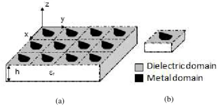
In the WCIP method the FSS analysis is reduced to that of the unit cell limited by periodic walls
shown as dashed lines in Fig. 1. The FSS unit cell is composed of two domains corresponding to the
metal domain and the dielectric domain as shown in Fig. 1.
Fig. 1. (a) Geometry of arbitrary FSS (b) Unit cell in the FSS structure.
The incident waves on the FSS unit cell and reflected waves from the FSS unit cell are
described at the boundaries interfaces as a function of the tangential electric field and the
transverse electric current densities as [11],[12]:
With:
is the transverse magnetic field, represents the wave impedance of the middle i, (i is the
medium index (i=1 ,2)), and it is expressed as: .
The diffracted waves at the kth iteration are obtained from the incident waves by [13]:
is the diffraction operator at the interface containing the FSS circuit and it is defined in the spatial domain. It is determined from the geometry of the planar unit cell and the boundary conditions
at the interface [14].
The diffracted waves are projected into periodic wall rectangular wave guide modes basis (TEM
mode, TE modes and TM modes) making a complete modal basis. Each resulting mode propagates
independently of the all the other modes since they are uncoupled in the modal domain. Thus each
Brazilian Microwave and Optoelectronics Society-SBMO received 10 Mar 2018; for review 23 Mar 2018; accepted 26 Sep 2018
Brazilian Society of Electromagnetism-SBMag © 2018 SBMO/SBMag ISSN 2179-1074 mode is reflected with a specific reflection coefficient [15] at the dielectric medium discontinuity
made by the substrate and the air due to the hypothetical rectangular waveguide’s modes closing
impedances. Thus the reflection operator in defined in the modal domain .
The reflected waves are equal and the next iteration incident waves of the (k+1)th
iteration is obtained by adding the wave source to the reflected waves [13] as:
Where is the reflection operator defined in the modal domain.
The fast modal transform (FMT) and its inverse (FMT-1) necessary at each iteration and given in
[13, 16, 17,18] allows the transition from the spatial domain to the modal domain and vice versa as:
The iterative procedure is repeated until convergence of the input admittance Yin is obtained. The
WCIP method’s convergence is ensured independently of the analyzed structure due to bounded
reflection operator.
The tangential electric and magnetic fields can be calculated from the diffracted waves and the
reflected waves as [16]:
III. FILTER CONFIGURATION
Initially, the FSS arrangement shown in Fig. 2 is presented to obtain dual polarized multiband FSS
structures with patterns offering easy comprehended resonances sources via simple equivalent LC
circuits. The linear metallic strip FSS comes to bring this advantage, but the strips coupling affects all
the resonances if the length of one strip is altered. To overcome this drawback many simulations are
achieved during the parametric study to end with strips spacing resulting in non coupled metallic
strips FSS structures. Hence, the resulted FSS is made of linear metallic strips independent in both the
spatial domain and the spectral domain. The choice of the strips lengths is made in such a way to
obtain resonances in the frequency range that can be measured at the GTEMA/CEFET-PB laboratory
Brazilian Microwave and Optoelectronics Society-SBMO received 10 Mar 2018; for review 23 Mar 2018; accepted 26 Sep 2018
Brazilian Society of Electromagnetism-SBMag © 2018 SBMO/SBMag ISSN 2179-1074 chosen to be 1mm since the available substrates at the laboratory are those with thicknesses of 0.8mm,
1mm, and 1.5mm and a dielectric constant of 4.4 because it is made of fiber glass (FR-4), in addition
to cell dimensions fixed to be 20mmx20mm.
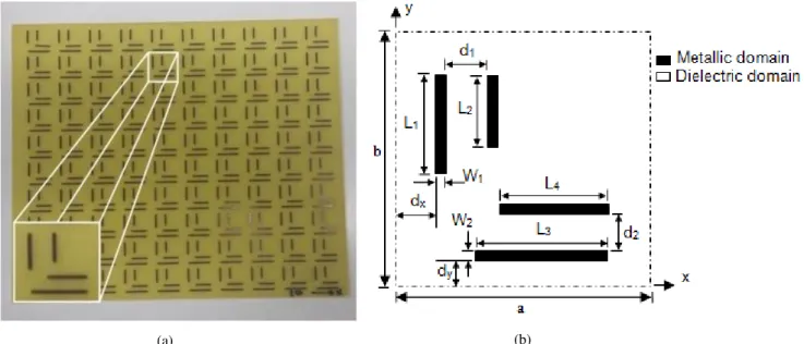
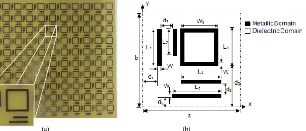
The filter configuration is presented in Fig. 2.a. The structure is fabricated from copper and etched
on a 1mm thickness substrate with relative dielectric constant of 4.4. The geometrical dimensions of
the proposed FSS unit cell shown in Fig. 2.b have the following values: a=b=20mm, L1=9.61mm,
L2=7.532mm, L3=13.684mm, L4=9.736mm, W1=0.789mm, W2=0.779mm, and d1= 5.263mm,
d2=3.376mm, dx=2.7mm, dy=1.8mm.
The FSS structure is excited with an x and y polarized normal incident plane waves. The WCIP
results are compared to the simulated results, and the measurements .The experimental results are
done on FSS of arrays consisting of unit cells as shown in Fig. 2.a.
Fig. 2. The parallel metallic strips FSS: (a) Realized FSS with an array of 10unit cells and (b) FSS unit cell geometry.
IV. RESULTS AND DISCUSSION
The FSS unit cell interface of Fig. 2.b is described by 200×200 pixels and the iterative process is
stopped after 350 iterations.
The WCIP results are validated by comparing them to the simulated results and the experimental
results.
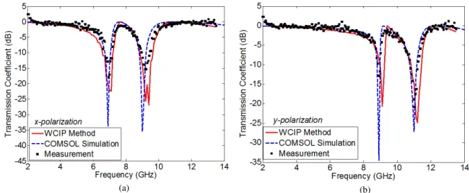
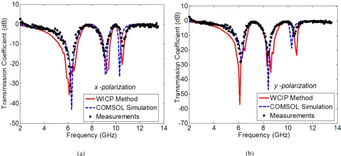
The transmission coefficients S12 of the parallel metallic strips FSS of Fig. 2 when the structure is
excited by an x and y polarized normal plane waves are shown in Figs. 3.a and 3.b respectively. The
simulated and measured results show a good agreement.
As shown in Fig. 3 the structure presents two resonant frequencies at about 7.1GHz and 9.4GHz
with bandwidths of 0.646GHz, 0.793GHz at -10dB respectively when it is excited with an x polarized
plane wave, and two resonant frequencies at about 9.1GHz and 11.2GHz with bandwidths of
Brazilian Microwave and Optoelectronics Society-SBMO received 10 Mar 2018; for review 23 Mar 2018; accepted 26 Sep 2018
Brazilian Society of Electromagnetism-SBMag © 2018 SBMO/SBMag ISSN 2179-1074 280.3MHz, 63MHz respectively when the structure is excited with a y polarized plane wave.
Fig. 3. Simulated and measured transmission coefficient for the : (a) x polarization – (b) y polarization.
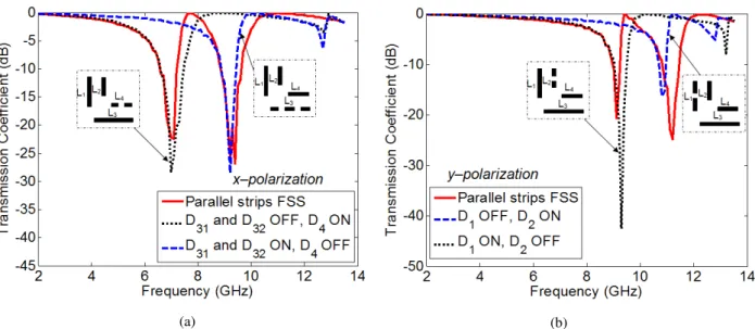
A. Metallic strips coupling effect study
To study the metallic strips coupling effect of the structure shown in Fig. 2 one strip at a time is
eliminated to lead to a structure with three strips. Figs. 4.a and 4.b present the transmission coefficient
of the four possible structures. Figs. 3.a and 3.b respectively shows that the elimination of a metallic
strip results in an elimination of its corresponding resonance without altering the other resonances
created by the remaining strips. Thus there is no coupling between the strips of the proposed structure
in Fig. 2.
Fig. 4. Simulated and measured transmission coefficient for the : (a) x polarization – (b) y polarization.
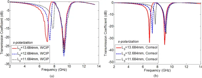
B. Frequencies tenability
The two resonant frequencies characterizing the FSS structure of Fig. 2.b and excited with an x
polarized plane wave source are adjusting by a variation in the strips dimensions L3 and L4.
The decrease of L3 from 13.684mm to 11.684mm allows the increase of the lowest resonance
frequency from 7 GHz to 7.8 GHz as shown in Figs. 5.a and 5.b. The increase of the second resonant
(a)
(a)
(b)
Brazilian Microwave and Optoelectronics Society-SBMO received 10 Mar 2018; for review 23 Mar 2018; accepted 26 Sep 2018
Brazilian Society of Electromagnetism-SBMag © 2018 SBMO/SBMag ISSN 2179-1074 frequency from 9.4 GHz to 10 GHz is observed when L4 decreases from 9.736 mm to 8.736mm
respectively as shown in Fig. 6.a and 6.b. The obtained WCIP method results are compared to the
simulated results, and a good agreement is reported.
Fig. 5. Transmission coefficient versus frequency for different Values of L3 for the x polarization : (a) WCIP results - (b)
Simulated results.
Fig. 6. Transmission coefficient versus frequency for different Values of L4 for the x polarization : (a) WCIP results - (b)
Simulated results.
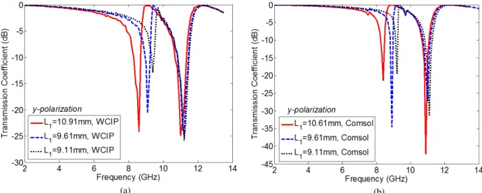
In the case of the y-polarized source, the two resonant frequencies are tuned by the variation of the
parallel strips dimensions L1 and L2, the increase of the lowest resonance frequency from 9.1 GHz to
9.7 GHz is achieved by the decrease of L1 from 9.61 mm to 8.61mm as shown in Figs. 7.a and 7.b.
The increase of the higher resonant frequency from 11.2 GHz to 11.9 GHz is observed when L2
decreases from 7.532 mm to 6.532 mm as shown in Figs. 8.a and 8.b.
Hence the different resonant frequencies can be independently controlled by only varying the strips
lengths L1, L2, L3, L4. Moreover the resonances can be separately eliminated by only removing the
strip responsible of the resonance. The simulated results obtained using WCIP are compared to the
simulated results and a good agreement is reported.
(a) (b)
Brazilian Microwave and Optoelectronics Society-SBMO received 10 Mar 2018; for review 23 Mar 2018; accepted 26 Sep 2018
Brazilian Society of Electromagnetism-SBMag © 2018 SBMO/SBMag ISSN 2179-1074
Fig. 7. Transmission coefficient versus frequency for different Values of L1for the y polarization : (a) WCIP results - (b)
Simulated results.
Fig. 8. Transmission coefficient versus frequency for different Values of L2 for the y polarization : (a) WCIP results - (b)
Simulated results.
The resonant frequency of a linear metallic strip FSS simulated by the WCIP method and calculated
also by equations (10) and (11) [19-21] is given in Table I for different strip lengths.
TABLE I. ERRORPERCENTOFTHERESONANTFREQUENCIES CORRESPONDING TO THE METALLIC STRIP L3
L3 (mm) Resonant frequencies WCIP
Method
Resonant frequencies (Equation 10)
Error %
13.684 7 6.67 4.71 12.684 7.4 7.19 2.83 11.684 7.8 7.81 0.12
(b) (a)
Brazilian Microwave and Optoelectronics Society-SBMO received 10 Mar 2018; for review 23 Mar 2018; accepted 26 Sep 2018
Brazilian Society of Electromagnetism-SBMag © 2018 SBMO/SBMag ISSN 2179-1074 The error rises from the non precise given in equation (11). The resonant frequency of a
rectangular metallic ring FSS can be also calculated by equations (10) and (11) by replacing the
parameter 2L by the ring outer circumference. Hence in order to determine an FSS metallic strip/ring
length resonating at a given resonant frequency, a more precise approach is to be adopted.
C. Electronically controlled FSS resonant frequencies
The suppression of one of the resonant frequencies can be achieved by inserting a gap of
dimensions Wg×Lg=0.779mm×1mm at the appropriate position along the strip responsible of the
corresponding resonant frequency. An ideal ON/OFF switch can be used to design an FSS capable of
inserting a resonance or removing it as represented in Figs. 10.a and 10.b. In Fig. 2 the strip of length
L3 even though divided into two equal strips by inserting an ON/OFF switch, its resonance is not
eliminated but moved up and can be close or equal to the resonance created by one of the other
adjacent strips. To overcome this problem a second ideal ON/OFF switch is inserted as shown in Fig.
9a. In Fig. 9b, ideal ON/OFF diode switches are inserted instead of the gaps to end with an
electronically controlled FSS resonant frequencies.
Fig. 9. The parallel metallic strips FSS: (a) With gaps (b) With diode switches.
Fig. 10. Simulated transmission coefficient for the : (a) x polarization – (b) y polarization.
(a) (b)
Brazilian Microwave and Optoelectronics Society-SBMO received 10 Mar 2018; for review 23 Mar 2018; accepted 26 Sep 2018
Brazilian Society of Electromagnetism-SBMag © 2018 SBMO/SBMag ISSN 2179-1074 Figs. 11.a and 11.b show the transmission coefficient of the FSS of Fig. 9 for different switches
states using WCIP method and simulation. When the switches D31 and D32 are both OFF, the only
resonance present concerns the strip of length L4. If D32 is ON and D31 is maintained OFF, two
resonant frequencies are shown where the lowest is recorded at about 9GHz and it concerns the strip
of length L4 and the highest resonant frequency observed at about 10.1GHz concerns the strip of
length 8mm extracted from the strip L3 by decrementing its length with 5.684mm. In the case where
the D 31 is ON and D32 is OFF, an improvement of 98.44% of the bandwidth centered at 9.2GHz is
obtained as compared to the structure of Fig. 2. It is due to the creation of new near L4 resonance by
the second strip constituting L3 strip of length 9.684mm.
Fig. 11. Simulated transmission coefficient for the x polarized FSS : (a) WCIP results – (b) Simulated results.
To add a third resonance in the x polarization, a horizontal strip is added as shown in Fig. 12.
Fig. 12. Parallel metallic strips FSS with three horizontal strips.
Brazilian Microwave and Optoelectronics Society-SBMO received 10 Mar 2018; for review 23 Mar 2018; accepted 26 Sep 2018
Brazilian Society of Electromagnetism-SBMag © 2018 SBMO/SBMag ISSN 2179-1074 The structure of Fig. 12 has the following dimensions: a=b=20mm, L1=11.81mm, L2=7.868mm,
L3=13.5081mm, L4=10.868mm, L5=7.868mm, W=0.983mm and d1=1.983mm, d2=d3=2.752mm,
dx=dy=1.2mm.
In the x polarization three resonant frequencies are observed at about 7 GHz, 8.6GHz and 11GHz as
shown in Fig. 13.a. In the y polarization two resonant frequencies of about 7.9GHz and 10.6GHz are
observed as represented by Fig. 13.b. In addition to the results obtained by the WCIP method,
simulated results are also plotted on Figs. 13.a and 13.b, and a good agreement is reported.
(a) (b)
Fig. 13. Simulated transmission coefficient for the: (a) x polarization – (b) y polarization.
To save a space and get three resonant frequencies in both directions of polarization a rectangular
ring is added in the structure of Fig. 2. Fig. 14 shows the designed and fabricated novel structure
where the geometrical dimensions of the proposed FSS unit cell are: a=b=20mm, L1=10.81mm,
L2=L4=7.868mm, L3=9.5081, W=0.983mm, and d1=d2=0.983mm, Wa=La=11.8mm, d3=5.9mm,
dx=dy=1.2mm.
(a) (b)
Brazilian Microwave and Optoelectronics Society-SBMO received 10 Mar 2018; for review 23 Mar 2018; accepted 26 Sep 2018
Brazilian Society of Electromagnetism-SBMag © 2018 SBMO/SBMag ISSN 2179-1074 The FSS unit cell of Fig. 14b is described by 200×200 pixels and the iterative process is stopped
after 350 iterations.
The WCIP results are validated by comparing them to the simulated results and the experimental
results, a good agreement is observed.
The transmission coefficients S12 of the structure when it is excited by an x and y polarized normal
plane waves are shown in Figs. 15.a and 15.b respectively.
(a) (b)
Fig. 15. Simulated and measured transmission coefficient for the: (a) x polarization - (b) y polarization.
As shown in Fig. 15 the structure presents three resonant frequencies at about 6.1GHz, 9.3GHz and
10.5GH with bandwidths of 1.554GHz, 0.632GHz and 28.1MHz at -10dB respectively when it is
excited with an x polarized plane wave, and three resonant frequencies at about 6.1GHz, 8.3GHz and
10.7GHz with bandwidths of 1.446GHz, 0.93 GHz and 27.6MHz respectively when the structure is
excited with a y polarized plane wave. In addition to the results obtained by the WCIP method,
simulated results are also plotted on Figs. 15.a. and 15.b, and a good agreement is reported.
V. FSS SYNTHESIS BASED ON NON COUPLED PARALLEL METALLIC STRIPS AND A RING
A multiband FSS with dual polarization can be synthesized only by giving the corresponding strips
lengths and their number being equal to the number of the desired resonant frequencies in the two
polarizations.
The structure that can be fabricated in the laboratory is an array of 10x10 cells with cell dimensions
a=b=20mm, a substrate thickness of 1mm and a relative dielectric constant of 4.4.
An FSS with an adjusted resonant frequency can be also obtained from rectangular metallic ring
length’s variation since its resonance occurs when the operating wavelength is equal to the
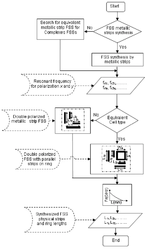
circumference of the ring. The outlines of the procedure of FSS synthesis based on metallic strips and
Brazilian Microwave and Optoelectronics Society-SBMO received 10 Mar 2018; for review 23 Mar 2018; accepted 26 Sep 2018
Brazilian Society of Electromagnetism-SBMag © 2018 SBMO/SBMag ISSN 2179-1074
Fig. 16. Strips length and ring circumference determination procedure outlines.
A. Metallic strip/ring length determination for a desired resonant frequency
The configuration of the metallic strip unit cell and metallic ring unit cell are presented in Figs. 17.a
and 17.b respectively. In the case of a metallic strip FSS unit cell of Fig. 17.a, the geometrical
dimensions are: a=b=20mm, a strip width W=0.789mm and the strip length L is ranging from 6mm to
19mm with an increment of 1mm. For the metallic ring FSS geometry of Fig. 17.b having the same
Brazilian Microwave and Optoelectronics Society-SBMO received 10 Mar 2018; for review 23 Mar 2018; accepted 26 Sep 2018
Brazilian Society of Electromagnetism-SBMag © 2018 SBMO/SBMag ISSN 2179-1074 length La varies from 5mm to 16mm. The FSS structures substrate have a 1 mm thickness and a 4.4
dielectric constant. They are excited with an x-polarized normal incident plane wave.
Fig. 17. FSS unit cell geometry : (a) Metallic strip - (b) Metallic ring.
The presented approach is summarized in the flowchart shown in Fig. 18. First of all, the type of FSS
is to be chosen between an FSS made of only parallel metallic strips and an FSS made of parallel
metallic strips and a ring. Once the FSS type is chosen, the desired resonant frequencies are inserted
once a time in Fig. 19 and the corresponding curve either the strip curve or the ring curve is used to
extract the strips length and/or the ring length La representing the remaining dimension to be
determined in order to end with an FSS with the desired frequency response.
Using the WCIP method and the simulator, the resonant frequency of the FSS structures of Fig. 17
is calculated for different values of L and La and shown in Fig. 18 in which the interpolation (solid and
dashed lines) is insured by the use of the least mean square method. At this stage, FSS with one
resonant frequency ranging from 4.5GHz to 12.25GHz can be realized by only using one metallic
strip. For more resonances additional metallic strips corresponding to the desired resonant frequencies
are inserted and arranged as presented in Fig. 2 since it was shown that no coupling exist between the
metallic strips under this arrangement.
Figure 18 presents a flowchart summarizing the different steps of obtaining the resonant frequency
fras a function of the strip’s length L and as a function of a ring length La. In Fig. 19, the obtained
characteristic plot relating the desired resonant frequency to the strip’s length L or the ring’s length La is shown. The obtained characteristic plot limits the synthesized FSS resonant frequencies to range
from 4.8GHZ to 12 GHz however the synthesized metallic ring FSS resonant frequencies are
restricted to the interval varying from 5GHZ to 8GHz.
.
Brazilian Microwave and Optoelectronics Society-SBMO received 10 Mar 2018; for review 23 Mar 2018; accepted 26 Sep 2018
Brazilian Society of Electromagnetism-SBMag © 2018 SBMO/SBMag ISSN 2179-1074
Brazilian Microwave and Optoelectronics Society-SBMO received 10 Mar 2018; for review 23 Mar 2018; accepted 26 Sep 2018
Brazilian Society of Electromagnetism-SBMag © 2018 SBMO/SBMag ISSN 2179-1074
Fig. 19. Resonance frequency as a function of the metallic strip length.
B. Approach validation
To validate the proposed approach, the measured results shown in Figs. 3.a and 3.b, 15.a and 15.b
and concerning respectively the dual polarized parallel metallic strip FSS of Fig. 2 and the dual
polarized FSS with parallel metallic strips and a ring of Fig. 14 are taken as references.
Dual polarized parallel metallic strips FSS:
Tables II and III show the values of the metallic striplength Li obtained from Fig. 19 and necessary to realize the measured resonant frequencies of Figs. 3.a
and 3.b respectively. The transmission power of the present approach dual polarized parallel metallic
strips FSS calculated by the WCIP method are shown in Figs. 20.a and 20.b for both source
polarizations x and y respectively.
TABLE II.ERROR IN THE PRESENT APPROACH RESONANT FREQUENCY AS COMPARED TO THE MEASURED RESONANT FREQUENCY FOR AN X POLARIZED SOURCE EXCITING THE DUAL POLARIZED PARALLEL METALLIC STRIPS FSS
Polarization x
fr (measured)
fr1 fr2
6.945 9.245
Li 14.154 9.902
fr_WCIP (GHz) 6.9 9.1
fr Eq. (10) 9.12 13.037
Error % WCIP 0.64 1.56
Brazilian Microwave and Optoelectronics Society-SBMO received 10 Mar 2018; for review 23 Mar 2018; accepted 26 Sep 2018
Brazilian Society of Electromagnetism-SBMag © 2018 SBMO/SBMag ISSN 2179-1074
TABLE III.ERROR IN THE PRESENT APPROACH RESONANT FREQUENCY AS COMPARED TO THE MEASURED RESONANT FREQUENCY FOR A Y POLARIZED SOURCE EXCITING A DUAL POLARIZED PARALLEL METALLIC STRIPS FSS
Polarization y
fr (measured)
fr2
8.9 11.03
Li 10.48 7.42
fr_WCIP (GHz) 8.6 11.3
fr Eq. (10) 12.953 18.145
Error % WCIP 3.37 2.44
Error % Eq. (10) 45.54 64.51
The recorded error in the resonant frequency obtained by the proposed approach as compared to
measurement varies from 0.64% to 3.37% whereas the error produced using equations (10) and (11)
reaches 64.51%.
Fig. 20. Transmission Coefficient of the dual polarized parallel metallic strips FSS the equivalent metallic structure for the: (a) x polarization - (b) y polarization.
Dual polarized FSS with parallel metallic strips and a ring:Table IV and Table V show the ring and
strip lengths La, L1, L2 represented by Li values and corresponding to the measured resonant
frequencies of 6GHz, 9.073GHz and 10.57GHz respectively. The measured resonant frequencies
concern the dual polarized metallic ring and parallel strips FSS shown in Fig. 14 and for which the
measurements are presented in Figs. 15.a and 15.b for x-polarized and y-polarized sources
respectively and exciting the FSS of Fig. 14. The transmission power of the present approach dual
polarized FSS with parallel metallic strips and a ring calculated by the WCIP method are shown in
Figs. 21.a and 21.b for both source polarizations x and y respectively.
Brazilian Microwave and Optoelectronics Society-SBMO received 10 Mar 2018; for review 23 Mar 2018; accepted 26 Sep 2018
Brazilian Society of Electromagnetism-SBMag © 2018 SBMO/SBMag ISSN 2179-1074
TABLE IV.ERROR IN THE PRESENT APPROACH RESONANT FREQUENCY AS COMPARED TO THE MEASURED RESONANT FREQUENCY FOR AN X POLARIZED SOURCE EXCITING THE DUAL POLARIZED FSS WITH PARALLEL METALLIC STRIP AND A RING
Polarization x
fr (measured)
fr1 fr2 fr3
6.255 9.073 10.57
Li 12.105 10.143 8.04
fr_WCIP (GHz) 6 8.8 10.4
fr Eq. (10) 10.665 12.727 16.039
Error % WCIP 3.61 3.01 1.61
Error % Eq. (10) 70.50 40.27 51.74
TABLE V. ERROR IN THE PRESENT APPROACH RESONANT FREQUENCY AS COMPARED TO THE MEASURED RESONANT FREQUENCY FOR A Y POLARIZED SOURCE EXCITING THE DUAL POLARIZED FSS WITH PARALLEL METALLIC STRIP AND A RING
Polarization y
fr (measured)
fr1 fr2 fr3
6.14 8.383 10.51
Li 12.51 11.28 8.12
fr_WCIP (GHz) 6 8.2 10.4
fr Eq. (10) 10.32 11.444 15.884
Error % WCIP 2.2800 2.1800 1.0500
Error % Eq. (10) 68.08 36.51 51.31
Fig. 21. Transmission coefficient of the dual polarized FSS with metallic parallel strips and a ring for the: (a) x polarization - (b) y polarization.
As shown in Tables IV and V the error in the resonant frequencies calculated by the proposed
approach remains less than 3.61% however the error percent of the resonant frequencies calculated by
equations (10) and (11) varies between 36.51% and 70.50%.
The presented synthesis approach anticipates more precisely the resonant frequency of the metallic
strip/ring FSS. Using Fig. 19 to extract pairs of resonant frequencies and strip/ring lengths (fr, Li) then
inserting them a pair at a time in equation (12) obtained from equation (10), a curve relating the
Brazilian Microwave and Optoelectronics Society-SBMO received 10 Mar 2018; for review 23 Mar 2018; accepted 26 Sep 2018
Brazilian Society of Electromagnetism-SBMag © 2018 SBMO/SBMag ISSN 2179-1074 relative effective dielectric constant of the FSS and the resonant frequencies or the strip/ring
length are obtained and shown in Fig. 22. As a result equation (10) and the resulting curves also
provide errors in the strip/ring FSS resonant frequencies determination less than 4.25% and errors in
the strip/ring length of also less than 4.25% as shown in Figs. 23 and 24 respectively since they are
issued from the same synthesis and analysis approaches.
The difference between the experiment results and the simulated results are probably due to the non
exact value of the substrate dielectric constant of the manufactured FSS since its is provided by the
constructor and not extracted from experiment before measuring the manufactured FSS. A part of this
difference may be related to the use of a limited number of TE and TM modes arising from the limited
number of pixels describing the FSS interface. In addition the iterative procedure of the WCIP method
is stopped at a limited number of iterations presenting initially an accepted error in the determination
of the reflection and transmission coefficients.
Fig. 22. Effective dielectric constant as a function of the: (a) Metallic FSS metallic strip/ring length (b) Resonant frequency of the strip/ring FSS
C. Approach error estimation
The synthesis approach error in the FSS’s
strip/ring length as a function of the desired
resonant frequency of the metallic strip/ring FSS is shown in Fig. 23 where a maximum error
of 4.25% in the strip length is recorded for a desired resonant frequency of 9.18GHz. Fig. 24
presents the analysis approach error in the resonant frequency of the metallic strip/ring FSS
as a function of a given FSS’s strip/ring length where the maximum error
of 4.25% is
observed for the strip FSS of 10 mm length. The errors are identical since a metallic strip
FSS of 10mm length resonates at 9.2GHz. When comparing the least square method results
to those of the WCIP method the error is lower since the WCIP method results are used as the
r_e
ff
(a) (b)
r_e
Brazilian Microwave and Optoelectronics Society-SBMO received 10 Mar 2018; for review 23 Mar 2018; accepted 26 Sep 2018
Brazilian Society of Electromagnetism-SBMag © 2018 SBMO/SBMag ISSN 2179-1074
basis data to obtain the least square method curve. Comparing the simulation curve to the
least square curve, a higher error value is recorded in the majority part of the
frequency/length range since there is an initial error between the WCIP results and the
simulation results as it can be seen in Figs 3, 13 and 15 due to the limited number of modes
used as a modal basis in the WCIP method. Moreover also the limited number of iterations
imposing an acceptable error after the iterative process convergence represents an additional
source of error.
Fig. 23. Strip/ring length error versus the desired resonant frequency for: (b) Metallic strip FSS (c) Metallic ring FSS
Fig. 24. Strip/ring resonant frequency error versus given strip/ring lengths for: (b) Metallic strip FSS (c) Metallic ring FSS
(a) (b)
Brazilian Microwave and Optoelectronics Society-SBMO received 10 Mar 2018; for review 23 Mar 2018; accepted 26 Sep 2018
Brazilian Society of Electromagnetism-SBMag © 2018 SBMO/SBMag ISSN 2179-1074 VI. EQUIVALENT STRUCTURE OF AN OPEN NOTCHED QUASI-SQUARE METALLIC RING BASED ON
METALLIC STRIPS
The comprehension of the electromagnetic behavior of a structure makes it more useful. Complex
structures don’t always offer this characteristic. Thus, introducing an approach for obtaining equivalent structures based on non coupled metallic strips is important in such a way that each
resonant frequency of the equivalent structure can be easily represented by a simple independent
resonant circuit.
In this part the equivalent structure of an open notched quasi-square metallic ring shown in Fig. 25
is determined and it is based on parallel metallic strips. The structure presented in [22] has three
resonant frequencies at about 9GHz, 11.6GHz and 12GHz for an x polarized source and 6.8GHz in the
case of a y polarized source. Using Fig. 19, each resonant frequency gives a value of the physical
metallic strip’s length that can produce this resonant frequency. By adopting the arrangement shown
in Fig. 2.b, the metallic strips are not coupled. Hence each resonant frequency can be independently
produced by one metallic strip.
Fig. 25. The open notched quasi-square metallic ring FSS unit cell dimensions [22].
The equivalent FSS based on parallel metallic strips is depicted in Fig. 26. It has three strips in the x
directions corresponding to three resonant frequencies when the structure is excited with an x
polarized plane wave source, and a single strip in the y direction to produce one resonant frequency
when the structure is excited with a y polarized plane wave.
The equivalent structure shown in Fig. 26 has the following dimensions: a=b=20mm, L1=10.3mm,
Brazilian Microwave and Optoelectronics Society-SBMO received 10 Mar 2018; for review 23 Mar 2018; accepted 26 Sep 2018
Brazilian Society of Electromagnetism-SBMag © 2018 SBMO/SBMag ISSN 2179-1074
Fig. 26. Unit cell of the equivalent dual polarized FSS based on parallel metallic strips.
Table VI shows the obtained strips lengths using the present approach based on Fig. 19. It provides
also the error in the present approach resonant frequency as compared to the measured resonant
frequencies of [22] for both x and y polarized sources exciting the equivalent dual polarized FSS
based on parallel metallic strips. It does not exceed 2.9% recorded for the y polarized source.
TABLE VI. EQUIVALENT FSS STRIPS LENGTHS AND RESONANT FREQUENCY ERROR AS COMPARED TO MEASUREMENTS Polarization x Polarization y
fr (measured)
fr1 fr2 fr3 fr1
9 10.8 11.6 6.8
Li 10.3 7.4 6.7 14.9
fr_WCIP (GHz) 8.8 11 11.8 6.6
Error % (WCIP) 2.22 0.9 1.7 2.9
The transmission power of the open notched quasi-square metallic ring [22] shown in Fig. 25 and
its equivalent structure based on metallic strip shown in Fig. 26 for the x and y polarization directions
are shown in Fig. 27.
Brazilian Microwave and Optoelectronics Society-SBMO received 10 Mar 2018; for review 23 Mar 2018; accepted 26 Sep 2018
Brazilian Society of Electromagnetism-SBMag © 2018 SBMO/SBMag ISSN 2179-1074 VII. CONCLUSION
A Dual polarized parallel metallic strips FSS and dual polarized FSS with parallel metallic strips and
a ring for multi band applications are proposed. The first proposed structure shows two resonant
frequencies at 7 GHz, 9.4GHz when the structure is excited with an x polarized plane wave, and two
resonant frequencies at 9.1GHzand 11.2GHz for the orthogonal source polarization. The second
proposed FSS structure shows three resonant frequencies for the x polarized source at 6.1GHz,
9.3GHz 10.5GHz and three resonant frequencies for the y polarized source at 6.1GHz 8.3GHz
10.7GHz. A resonant frequency can be eliminated when needed by only inserting an ideal ON/OFF
switch at the appropriate position along the strip responsible of this resonance. The two structures are
manufactured and measured. Good agreement is recorded between WCIP results, simulated results
and measurements. Next, an FSS synthesis approach based on non coupled metallic strips and a ring
is proposed and validated by measurements of the two manufactured structures. The recorded errors
don’t exceed 3.61% when comparing the desired resonant frequencies to the obtained resonant frequencies by analyzing the synthesized FSS. Finally, the proposed FSS synthesis based on parallel
metallic strips is used to determine the equivalent structure of an open notched quasi square ring FSS,
issued from literature for its complex electromagnetic behavior comprehension. It shows three
resonant frequencies for an x polarized source and one resonant frequency for the y polarized source.
The obtained equivalent metallic strips FSS resonant frequencies are compared to those of the open
notched quasi square ring FSS structure and good agreement is shown with an error remaining less
than 2.9%.
REFERENCES
[1] L. P. S. Antonio, Campos Adaildo, G. d'Assunção, Robson H., C., Maniçoba, Lincoln, M. Araújo, “Software for project and Analysis of Frequency Selective Surfaces,” Journal of Microwaves, Optoelectronics and Electromagnetic Applications, Vol. 11No. 1, pp. 56-67, 2012.
[2] S. Bera, S. Bandhu, P.P. Sarkar, “Design of Novel Shaped Compact Frequency Selective Surface with Dual band Applications,”International Journal of Electronics & Communication Technology, Vol. 4, pp. 29-32, 2013.
[3] A. Kaur, G. Er. Saini, Review of Various Designs of Periodic Structures for Frequency Selective Surfaces. International Journal of Engineering Trends and Technology, Vol .4, No. 5, pp. 29-250, 2016.
[4] C. Guo, H. Sun, and X. Lu, “A Novel Dual Band Frequency Selective Surface With Periodic Cell Perturbation,”
Progress In Electromagnetics ResearchB, Vol. 9, pp. 137-149, 2008.
[5] T. Mandal, P. S. Pratim, “A Dome Shaped Curved FSS with Extra Wide Band Applications: Design and Theoretical Analysis,” Journal of Electronics and Communication Engineering, Vol. 8, No. 1, pp. 53-55, 2013.
[6] Ghaffer. I. Kiani, Kenneth .L. Ford, Karu. P. Esselle, Andrew. R. Weily, C. Panagamuwa, John C. Batchelor, “Single
-Layer Bandpass Active Frequency Selective Surface,” Microwave and Optical Technology Letters. Vol. 50 No. 8, pp. 2149-2151, August 2008.
Brazilian Microwave and Optoelectronics Society-SBMO received 10 Mar 2018; for review 23 Mar 2018; accepted 26 Sep 2018
Brazilian Society of Electromagnetism-SBMag © 2018 SBMO/SBMag ISSN 2179-1074
[8] H. Baudrand, M. Titaouine and N. Raveu, “The Wave Concept in Electromagnetism and Circuits: Theory and Applications,” ISTE Ltd and John Wiley & Sons In. August 2016.
[9] M. K. Azizi, L. Latrach, N. Raveu, A. Gharsallah, H. Baudrand, “A New Approach Of almost Periodic Lumped
Elements Circuits By An Iterative Method Using Auxiliary Sources,” American Journal of Applied Sciences. Vol. 10 No. 11, pp. 1457-1472, 2013.
[10] A. Salouha, L. Latrach, A. Gharsallah, A. Gharbi, And H. Baudrand, “Characterization Of Switchable And Multilayered FSS Circuits Using The WCIP Method,” Int. Journal of Engineering Research and Applications, pp.109-116, November 2014.
[11] M. Latifa, L. Latrach, A. Gharsallah, “Analysis of an Almost Periodic Reconfigurable Circuits Using Iterative Method,”
International Journal of Applied Engineering Research. Vol. 11, No. 4, pp. 2508-2512, 2016.
[12] A. Zugari, N. Raveu, C. Girard, H. Baudrand, and M. Khalladi, ”A Fast Hybrid WCIP and FDTLM Approach to Study
Inhomogeneous Circuits,” Progress In Electromagnetics Research C. Vol. 51, pp. 55-62, 2014.
[13] S. Akatimagool, “Electromagnetic Software Tools for Microwave Multi-layer Integrated Circuits and Components,”
Journal of KMITNB. Vol. 13, No. 2, pp.7-11, Jun 2003.
[14] M. Titaouine, N. Raveu, A. G. Neto, “Dual-Band And Enhanced Band FSS Characterization Using WCIP Method,”
Microwave And Optical Technology Letters. 52, No. 4, pp. 836-839, April 2010.
[15] M. Titaouine, A. G. Neto, H.. Baudrand, and F. Djahli, “Analysis of Frequency Selective Surface on
Isotropic/Anisotropic Layers Using WCIP Method,” ETRI Journal. Vol. 29, No. 1, pp. 36-44, February 2007.
[16] R. Gharbi, H. Zairi , H. Trabelsi, H. Baudrand, “Analysis of Complex Electromagnetic Structures by Hybrid
FDTD/WCIP Method,” Journal of Electromagnetic Analysis and Applications. Vol. 4, pp. 497-503, 2012.
[17] M. Titaouine, A. G. Neto, H. Baudrand, and F. Djahli, “Determination Of Metallic Ring FSS Scattering Characteristics
using Wcip Method,” Microwave And Optical Technology Letters. Vol. 50, No. 5, pp. 1324-1328, May 2008.
[18] S. Aroussi, L. Latrach, N. Sboui, A. Gharsallah, A. Gharbi, H. Baudrand, “ Efficient Analysis of Complex FSS
Structure Using the WCIP Method,” Journal of Electromagnetic Analysis and Applications, Vol. 3, pp. 447-451, 2011.
[19] G. A. J. Adaildo, G. Fontgall, M. Titaouine, H. Baudrand, H. M. D. Nóbrega,. A. G. Neto, “Analysis of Tapered
Micostrip Patch Antenna by the Wave Concept Iterative Procedure,”IEEE, pp. 61-66, 2009.
[20] A. G. Neto, J. C. Silva, J. N. Carvalho, A. N. d. Silva, C. B. d. Aguiar, F. M. Deisy, “Analysis of Frequency Selective Surface with U-Shaped Geometry,” Journal of Microwaves, Optoelectronics and Electromagnetic Applications, Vol. 14, pp. 113-122, 2015.
[21] Jia-Sheng Hong, Lancaster, M.J. “Microstrip Filters for RF/Microwave Applications,” John Wiley & Sons, Inc. 2001. [22] I. Adoui, M. Titaouine, H. Choutri, A. Djouimaa, T. R. De Sousa, A. G. Neto, H. Baudrand, “Characterization Of