Universidade do Minho
Escola de Engenharia
Nuno Filipe Antunes Oliveira Ferreira Alves
Biped locomotion control through a
biologically-inspired closed-loop controller
UMinho|20
12
N
uno F
ilipe Antunes Oliv
eir a F err eir a Alv es Biped locomo tion control t hrough a biologicall
Dissertação de Mestrado
Ciclo de Estudos Integrados Conducentes ao
Grau de Mestre em Engenharia Biomédica
Trabalho realizado sob a orientação da
Professora Doutora Cristina P. Santos
Universidade do Minho
e coorientação do
Doutor Juan C. Moreno
CSIC – Madrid
Universidade do Minho
Escola de Engenharia
Nuno Filipe Antunes Oliveira Ferreira Alves
Biped locomotion control through a
É AUTORIZADA A REPRODUÇÃO PARCIAL DESTA DISSERTAÇÃO APENAS PARA EFEITOS DE INVESTIGAÇÃO, MEDIANTE DECLARAÇÃO ESCRITA DO INTERESSADO, QUE A TAL SE COMPROMETE;
Acknowledgements
I would like to express all my gratefulness to my advisor Cristina Santos, for her continu-ous and opportune supervising, always paying attention to the detail and giving me important advices to work out this dissertation.
A special word goes to my other advisor Juan C. Moreno. His knowledge and experience in the area were fundamental to this work. He guided me along the training period and it was a real pleasure to work with him.
I also want to show gratitude to Jose Luis Pons, for the opportunity they gave me to work in such an important Research Center as CSIC (Consejo Superior de Investigaciones Cientificas- Madrid - Spain), as well as their support all through the internship term, which was greatly appreciated.
Sincere gratitude to my colleagues from the Bioengineering Group of CSIC and from the ASB (Adaptive System Behavior - Braga - Portugal) group should be noted with whom exchange of views on various issues have proven vitally important in promoting gradual development of this work as well as in highlighting and clarifying priority steps for the improvement of the study.
Finally, I want to thank to my family and friends all the support they have given me all year round, especially because they always believe in my work.
Abstract
Currently motor disability in industrialized countries due to neural and physical impair-ments is an increasingly worrying phenomenon and the percentage of patients is expected to be increasing continuously over the coming decades due to a process of ageing the world is undergoing. Additionally, rising retirement ages, higher demand of elderly people for an independent, dignified life and mobility, huge cost in the provision of health care are some other determinants that motivate the restoration of motor function as one of the main goals of rehabilitation. Modern concepts of motor learning favor a task-specific training in which all movements in daily life should be trained/assisted repetitively in a physically correct fashion. Considering the functional activity of the neuronal circuits within the spinal cord, namely the central pattern generator (CPG), as the foundation to human locomotion, motor relearn-ing should be based on intensive trainrelearn-ing strategies directed to the stimulation and reorgani-zation of such neural pathways through mechanisms addressed by neural plasticity. To this end, neuromodelings are required to simulate the human locomotion control to overcome the current technological challenges such as developing smaller, intelligent and cost-effective devices for home and work rehabilitation scenarios which can enable a continuous ther-apy/assistance to guide the impaired limbs in a gentle manner, avoiding abrupt perturbations and providing as little assistance as necessary. Biomimetic models, taking neurological and biomechanical inspiration from biological animals, have been embracing these challenges and developing effective solutions on refining the locomotion models in terms of energy efficiency, simplicity in the structure and robust adaptability to environment changes and unexpected perturbations.
Thus, the aim target of this work is to study the applicability of the CPG model for gait rehabilitation, either for assistance and/or therapy purposes. Focus is developed on the locomotion control to increase the knowledge of the underlying principles useful for gait restoration, exploring the brainstem-spinal-biomechanics interaction more fully. This study has great application in the project of autonomous robots and in the rehabilitation technology, not only in the project of prostheses and orthoses, but also in the searching of procedures that help to recuperate motor functions of human beings.
Encouraging results were obtained which pave the way towards the simulation of more complex behaviors and principles of human locomotion, consequently contributing for im-proved automated motor rehabilitation adapted to the rehabilitation emerging needs.
Resumo
Actualmente a debilidade motora em países industrializados devido a deficiências neurais e físicas é um fenómeno crescente de apreensão sendo expectável um contínuo aumento do rácio de pacientes nas próximas décadas devido ao processo de envelhecimento. Inclusivé, o aumento da idade de reforma, a maior procura por parte dos idosos para uma mobilidade e vida autónoma e condigna, o elevado custo nos cuidados de saúde são incentivos para a restauração da função motora como um dos objectivos principais da reabilitação. Conceitos recentes de aprendizagem motora apoiam um treino de tarefas específicas no qual movimen-tos no quotidiano devem ser treinados/assistidos de forma repetitiva e fisicamente correcta.
Considerando a actividade funcional dos circuitos neurais na medula, nomeadamente o gerador de padrão central (CPG), como a base da locomoção, a reaprendizagem mo-tora deve-se basear em estratégias intensivas de treino visando a estimulação e reorgani-zação desses vias neurais através de mecanismos abordados pela plasticidade neural. Assim, são necessários modelos neurais para simular o controlo da locomoção humana de modo a superar desafios tecnológicos actuais tais como o desenvolvimento de dispositivos mais compactos, inteligentes e económicos para os cenários de reabilitação domiciliar e laboral que podem permitir uma terapia/assistência contínua na guia dos membros debilitados de uma forma suave, evitando perturbações abruptas e fornecendo assistência na medida do necessário. Modelos biomiméticos, inspirando-se nos princípios neurológicos e biomecâni-cos dos animais, têm vindo a abraçar esses desafios e a desenvolver soluções eficazes na refinação de modelos de locomoção em termos da eficiência de energia, da simplicidade na estrutura e da adaptibilidade robusta face a alterações ambientais e perturbações inesperadas. Então, o objectivo principal do trabalho é estudar a aplicabilidade do modelo de CPG para a reabilitação da marcha, para efeitos de assistência e/ou terapia. É desenvolvido um foco no controlo da locomoção para maior entendimento dos princípios subjacentes úteis para a recu-peração da marcha, explorando a interacção tronco cerebral-espinal medula-biomecânica de forma mais detalhada. Este estudo tem potencial aplicação no projecto de robôs autónomos e na tecnologia de reabilitação, não só no desenvolvimento de ortóteses e próteses, mas tam-bém na procura de procedimentos úteis para a recuperação da função motora.
Foram obtidos resultados promissores susceptíveis de abrir caminho à simulação de com-portamentos e princípios mais complexos da marcha, contribuindo consequentemente para uma aprimorada reabilitação motora automatizada adaptada às necessidades emergentes.
Contents
1 Introduction 1 1.1 Motivation . . . 1 1.2 Problem formulation . . . 2 1.3 Solution . . . 3 1.4 Thesis structure . . . 72 State of the art of rehabilitation and assistive devices 8 2.1 Passive exoskeletons . . . 10
2.2 Active exoskeletons . . . 11
2.3 Functional electrical stimulation . . . 33
2.4 Hybrid exoskeletons . . . 34
2.5 Open research questions . . . 52
3 Central Pattern Generators (CPGs) 59 3.1 CPG-based locomotion modeling . . . 59
3.2 Movement primitives learning . . . 60
3.3 Hopf AFOs . . . 61
4 Overall system design 69 4.1 Biped walker system . . . 70
4.2 Locomotion control . . . 75
5 Methodology 94 5.1 Experimental setup . . . 94
5.2 Experimental procedures . . . 95
6 Results and discussion 104 6.1 CPG-orthosis in open-loop control experiment . . . 104 6.2 CPG-biped model in open-loop control . . . 107 6.3 CPG-biped model in closed-loop control . . . 109
7 Conclusions and future developments 136
Bibliography Appendix
A Biped model specifications 162
B Dynamic model formulas 163
List of Figures
2.1 Gait passive orthoses: 1(a) knee-ankle-foot orthosis (KAFO) [1]; 1(b) hip-knee-ankle-foot orthosis (HKAFO) [2]; 1(c) HKAFO orthosis with
recipro-cating mechanism on the hip joint [2]. . . 11
2.2 H.A.L. exoskeleton [3]. . . 13 2.3 T.U.P.L.E.E. prototype [4]. . . 14 2.4 P.I.G.R.O. prototype [5]. . . 15 2.5 eLegs exoskeleton [6]. . . 16 2.6 REX device [7]. . . 17 2.7 V.P.O. prototype [8]. . . 17 2.8 P.A.G.O. prototype [9]. . . 19 2.9 Roboknee exoskeleton [10]. . . 19 2.10 A.A.F.O. prototype [10]. . . 20 2.11 A.F.O.U.D. system [11]. . . 21 2.12 A.F.O.U.M. device [12]. . . 22 2.13 R.G.T. orthosis [13]. . . 23 2.14 A.A.F.O.U.Y. prototype [14]. . . 25 2.15 Anklebot exoskeleton [15]. . . 25 2.16 P.P.A.F.O. system [16]. . . 26 2.17 S.C.K.A.F.O. prototype [17]. . . 28 2.18 A.S.O.D. prototype [18]. . . 29 2.19 V.H.C.M. exoskeleton [19]. . . 36 2.20 C.B.O. exoskeleton [20]. . . 38
2.21 S.B.O. gait system [21]. . . 42
2.22 J.C.O. exoskeleton [22]. . . 42
2.23 E.S.O. exoskeleton [23]. . . 44
2.25 WalkTrainer exoskeleton [25]. . . 48
2.26 Rewalk orthosis [26]. . . 49
3.1 Oscillator’s state variables x and y. . . 63
3.2 Stability of the oscillator over time. . . 63
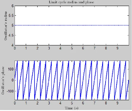
3.3 Oscillator’s radius and phase x and y. . . 64
3.4 Exhibition of a stable harmonic limit cycle. . . 64
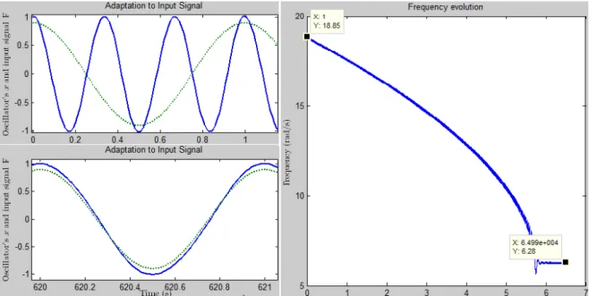
3.5 Frequency learning in the Hopf AFO. The learning input is a harmonic signal F= cos (2πt). The evolution of ω is shown on the right, where one can observe the adaptation to the desired input frequency and its phase-locking. On the left are depicted the oscillations of the Hopf oscillator (blue solid line) corresponding to x-state variable, at the onset of learning (upper graph) and after learning (lower graph), in addition to the plot of the input signal F (green dotted line). . . 65
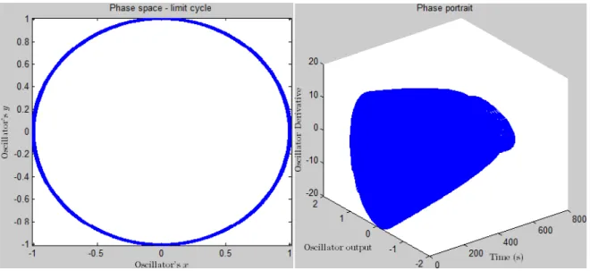
3.6 Exhibition of a stable harmonic limit cycle and of the stability of the oscillator over time. . 66
3.7 The figure illustrates the evolution of four intrinsic frequencies of the four oscillators, (ω1, ω2, ω3, ω4). Each oscillator can adapt its frequency to one of desired frequencies of the input signal. . . 67
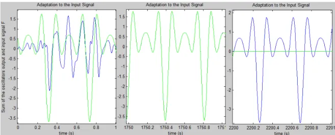
3.8 Frequency learning in the adaptive Hopf oscillators while receiving the input input, F = 0.8sin (15t)+ cos (30t) − 1.4sin (45t) − 0.5cos (60t). In the figure it is shown the sum of the oscillations of the Hopf oscillators corresponding to the x-state variable (solid blue line) in addition to the learning input signal (solid green line): at the onset of learning (left graph), after learning (center graph) and after removing the input signal (right graph). . . 68
4.1 Overall architecture control. . . 69
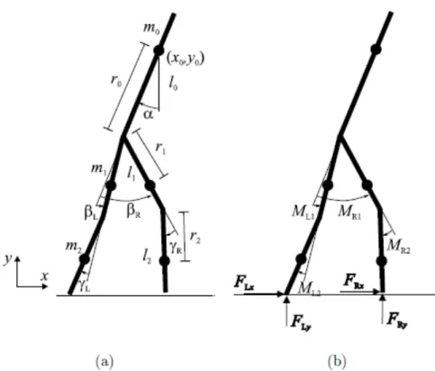
4.2 Schematic diagram of the biped walker stick man. . . 71
4.3 Schematic of the Biped walker system. . . 72
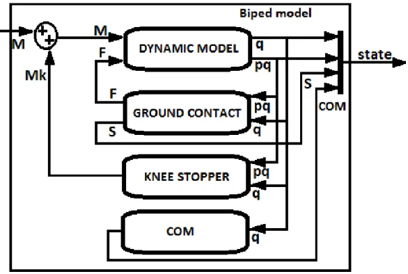
4.4 The blocks inside the Biped model block. . . 73
4.5 Schematic of the blocks with the PD ref controller block. This block is inside the Biped walkersystem (figure 4.1) . . . 74
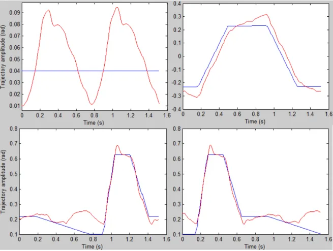
4.6 Comparison between the nominal reference trajectories from the stateCPGvector (solid blue line) and the real trajectory signals (solid red line) assumed by the biped system from the simulation model during a single stride period. - Top: trajectories relating the torso angle α (left) and the difference of the thigh angles∆β (right); - Bottom: trajectories regarding the left (left) and right (right) leg knee angles γLand γR. . . 75
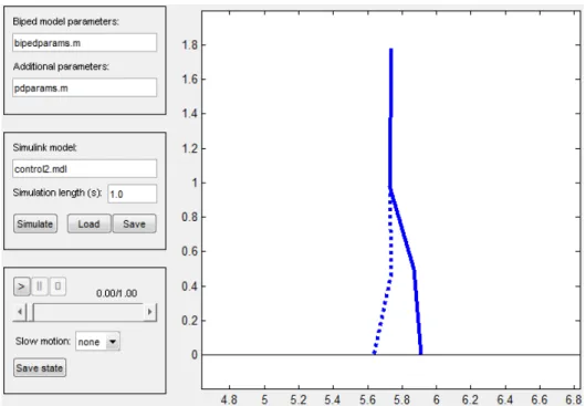
4.7 The graphical user interface for a controlled biped system simulation.. . . 76
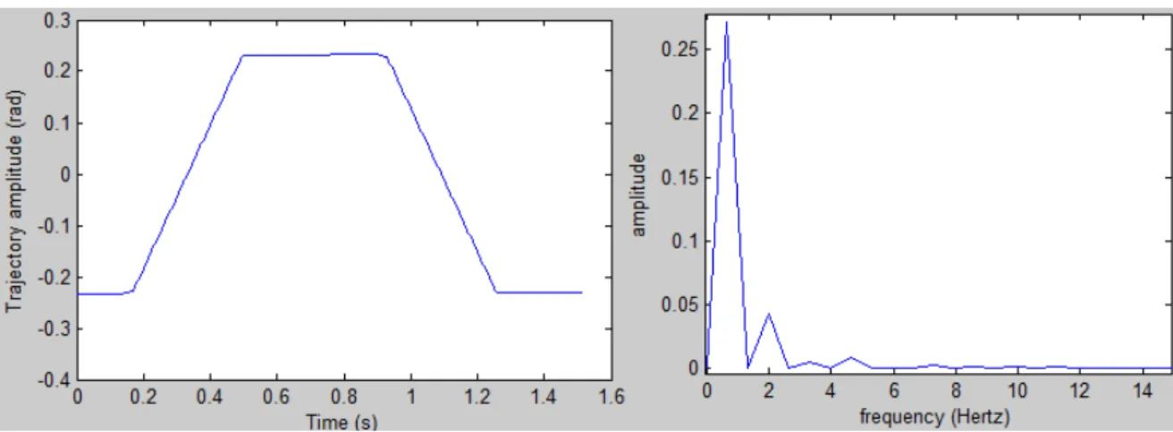
4.8 Difference of the thigh angles (∆β) and its frequency spectrum. . . 77
4.9 Left leg knee angle (γL) and its frequency spectrum. . . 77
4.10 Right leg knee angle (γR) and its frequency spectrum. . . 78
4.11 Torso angle (α) and its frequency spectrum. . . 78
4.12 Comparison between the nominal reference trajectories from the simulation model (solid blue line) and the manually reproduced signals (solid red line). - Top: trajectories con-cerning the torso angle α (left) and the difference of the thigh angles∆β (right); - Bottom: trajectories regarding the left (left) and right (right) leg knee angles γLand γR. . . 79
4.13 Schematic of the dynamic learning of the reference nominal trajectories. . . 80
4.14 Structure of the generic CPGs within the Generic CPGs block. A generic CPG is used for each DOF (∆β, γLand γR). The arrows connecting the first oscillators of each generic CPG represent the phase relationship between the CPGs. Each produced DOF trajectory is the weighted sum of the respective constituent oscillators of the respective CPG. . . 81
4.15 Structure of a generic CPG network of Hopf AFOs. The learning signal F(t)= learningS − P aixi is delivered to all oscillators, which is the difference between the signal to be learned, learningS, and the signal already learned, learnedS= P aixi. Unlike the oscillator 0, all the oscillators are given a phase contribution φifrom oscillator 0. For more details, consult [27, 28]. . . 81
4.16 Learning of the frequencies and associated amplitudes of the∆β reference signal in the thigh CPG. The error between the learningS and the learnedS signals is shown on the right, where one can observe its value converging to zero. On the left are depicted the oscillations of the Hopf oscillator (blue solid line) corresponding to x-state variable, at the onset of learning (upper graph) and after learning (lower graph), in addition to the plot of the input signal I (green solid line).. . . 84
4.17 Learning of the frequencies and associated amplitudes of the γL reference signal in the left knee CPG. The error between the learningS and the learnedS signals is shown on the right, where one can observe the its value converging to zero. On the left are depicted the oscillations of the Hopf oscillator (blue solid line) corresponding to x-state variable, at the onset of learning (upper graph) and after learning (lower graph), in addition to the plot of the input signal I (green solid line). . . 85
4.18 Learning of the frequencies and associated amplitudes of the γR reference signal in the right knee CPG. The error between the learningS and the learnedS signals is shown on the right, where one can observe the its value converging to zero. On the left are depicted the oscillations of the Hopf oscillator (blue solid line) corresponding to x-state variable, at the onset of learning (upper graph) and after learning (lower graph), in addition to the plot of the input signal I (green solid line). . . 85 4.19 Schematic of the reference signals generation by the CPG-based controller within the
Low-level controlsystem. The internal feedback stateHLC is represented in solid line, while the external feedback stateBPDis represented in dashed line.. . . 87
4.20 Limit cycle of a specific trajectory over time (left panel) and relating to the x − y state space (right panel). A perturbation is applied to x−state using a FT value of −400 within 0.715 − 0.72 s. . . 92 4.21 Limit cycle of a specific trajectory relating to the x − y state space. A perturbation is applied
to x−state, deviating its value to ≈ 0 within 0.715 − 0.72 s. . . 92
5.1 Sketch of the swinging task. The CPG generates the rhythmic signal to the controlled joint. 95 5.2 Stability analysis through the method of upper-body motion measure of a gait pattern
char-acterized as the normal walking gait on even ground. The behavior of the COP (magenta line), COMx(red line), stance leg tip (blue line) and swing leg tip (green line) is described. A single stride is simulated including the double support phase (DSP) and the single support phase (SSP). . . 100 5.3 The NN and the D-statistic determination [29]. . . 102 6.1 The CPG reference input (blue) and the real angle pattern (red) trajectories when using the
orthosis velocity controller. (a) total time simulation; (b) focus on the initial stage of the simulation. . . 105 6.2 The CPG reference input (blue) and the real angle pattern (red) trajectories when using the
orthosis position controller. (a) total time simulation; (b) focus on the initial stage of the simulation. . . 106 6.3 Comparison between the CPG reference (blue) and the biped system real (green)
trajecto-ries.∆β, γLand γRsignals are plotted at the top, middle, bottom, respectively. . . 108
6.4 Mechanical system amplitude oscillations of the stable oscillatory regime described by the biped COM without the integration of the feedback signal. . . 109
6.5 Mechanical system amplitude oscillations of the stable oscillatory regime described by the biped COM with the integration of the feedback signal and feedback gain ge= 1.0.. . . . 110
6.6 Mechanical system amplitude oscillations of the stable oscillatory regime described by the biped COM with the integration of the feedback signal and feedback gain ge= 2.0.. . . . 110
6.7 Comparison between the CPG reference (blue) and the biped system real (green) trajecto-ries.∆β, γLand γRsignals are plotted at the top, middle, bottom, respectively. . . 112
6.8 Stability analysis through the NNGI method of the locomotion characterized as a normal walking gait on even ground. The NN (gray dashed line) and the RLC (black solid line) are illustrated in the upper panel; the bottom panel shows the D-statistic (solid line). . . 113 6.9 Stability analysis through the method of upper-body motion measure of the locomotion
characterized as a normal walking gait on even ground. The behavior of the COP (magenta line), COMx(red line), stance leg tip (blue line) and swing leg tip (green line) is described throughout the total simulation (on the left panel) and during a single stride (on the right panel) for greater clarity and insight. . . 114 6.10 Stability analysis of the locomotion under the application of an internal perturbation in the
early swing (0.245- 0.745 s). (a) The NN (dashed line) and the RLC (solid line) are il-lustrated in the upper panel; the bottom panel shows the D-statistic (solid line). (b) The resultant limit cycle of the right knee joint is displayed. (c) The real trajectories assumed by the biped system. . . 115 6.11 Stability analysis of the locomotion under the application of an internal perturbation in the
late swing (0.535- 1.035 s). (a) The NN (dashed line) and the RLC (solid line) are illustrated in the upper panel; the bottom panel shows the D-statistic (solid line). (b) The resultant limit cycle of the right knee joint is displayed. (c) The real trajectories assumed by the biped system.116 6.12 Stability analysis of the locomotion under the application of an internal perturbation in the
stance phase (0.735- 1.235 s). (a) The NN (dashed line) and the RLC (solid line) are il-lustrated in the upper panel; the bottom panel shows the D-statistic (solid line). (b) The resultant limit cycle of the right knee joint is displayed. (c) The real trajectories assumed by the biped system. . . 117 6.13 Stability analysis through the method of upper-body motion measure of the locomotion on
tilted ground of 1.0◦ of slope. The behavior of the COP (magenta line), COMx(red line), stance leg tip (blue line) and swing leg tip (green line) is described throughout the total simulation. . . 118
6.14 Stability analysis through the method of upper-body motion measure of the locomotion on tilted ground of 1.0◦ of slope. The behavior of the COP (magenta line), COMx (red line), stance leg tip (blue line) and swing leg tip (green line) is described throughout the total simulation. αREF= 0.04rad. . . 120
6.15 Stability analysis through the method of upper-body motion measure of the locomotion on tilted ground of 1.0◦ of slope. The behavior of the COP (magenta line), COM
x (red line), stance leg tip (blue line) and swing leg tip (green line) is described throughout the total simulation. αREF= 0.05rad on the left panel; αREF= 0.07rad on the right panel. . . 121
6.16 Stability analysis through the method of upper-body motion measure of the locomotion on tilted ground of 1.0◦ of slope. The behavior of the COP (magenta line), COMx (red line), stance leg tip (blue line) and swing leg tip (green line) is described throughout the total simulation. αREF= 0.07rad. . . 121
6.17 Stability analysis through the method of upper-body motion measure of the locomotion on tilted ground of −0.8◦of slope. The behavior of the COP (magenta line), COMx(red line), stance leg tip (blue line) and swing leg tip (green line) is described throughout the total simulation. αREF= 0.04rad. . . 122
6.18 Stability analysis through the method of upper-body motion measure of the locomotion on tilted ground of −0.8◦of slope. The behavior of the COP (magenta line), COM
x(red line), stance leg tip (blue line) and swing leg tip (green line) is described throughout the total simulation. αREF= 0.015rad on the left panel; (b) αREF= 0.005rad on the right panel. . . 123
6.19 Simulation of the biped locomotion on a complex terrain with positive, zero and negative slopes, respectively. (a) Stability analysis through the method of upper-body motion mea-sure; the behavior of the COP (magenta line), COMx (red line), stance leg tip (blue line) and swing leg tip (green line) is described throughout the total simulation; (b) Adaptation of αREFaccording to the floor slope; (c) Height from the floor with the respective slopes. . 124
6.20 Simulation of the biped locomotion on a complex terrain with negative, zero and positive slopes, respectively. (a) Stability analysis through the method of upper-body motion mea-sure; the behavior of the COP (magenta line), COMx (red line), stance leg tip (blue line) and swing leg tip (green line) is described throughout the total simulation; (b) Adaptation of αREFaccording to the floor slope; (c) Height from the floor with the respective slopes. . 125
6.21 Different slopes in simulation. Upslope and downslope are shown, respectively, separated by flat surface. The upslope and downslope angles are respectively ≈+1.56◦and ≈ −0.81◦. 126
6.22 Different slopes in simulation. Downslope and upslope are shown, respectively, separated by flat surface. The upslope and downslope angles are respectively ≈ −0.81◦and ≈+1.56◦. 127 6.23 Actual mean step length versus the slope angle of the floor. The biped system can walk
stably in this range of floor slope angles. . . 127 6.24 Actual mean gait velocity versus the slope angle of the floor. The biped system can walk
stably in this range of floor slope angles. . . 128 6.25 Slope angle of+3.0◦ in simulation. (a) Stick figure of the biped system traced at 0s, 7.03s
and 10.0s; (b) on the left panel is illustrated the stability analysis through the method of upper-body motion measure, while on the right panel is depicted the modulation of αREF. . 129
6.26 Slope angle of −2.5◦in simulation. (a) Stick figure of the biped system traced at 0s, 7.3s and 10.0s; (b) on the left panel is illustrated the stability analysis through the method of upper-body motion measure, while on the right panel is depicted the modulation of αREF . 130
6.27 On the upper panel is the stability analysis through the method of upper-body motion mea-sure of the locomotion on uneven ground with an obstacle of 0.05m high; the behavior of the COP (magenta line), COMx(red line), stance leg tip (blue line) and swing leg tip (green line) is described throughout the total simulation. On the lower panel is depicted the presence of an obstacle. . . 131 6.28 Stability analysis. (a) Method of upper-body motion measure of the locomotion on uneven
ground with an obstacle of 0.05m high; the behavior of the COP (magenta line), COMx(red line), stance leg tip (blue line) and swing leg tip (green line) is described throughout the total simulation. (b) Method of perturbation detection under the presence of an obstacle; the NN (dashed line) and the RLC (solid line) are illustrated in the upper panel; the bottom panel shows the D-statistic (solid line) . . . 132 6.29 (a) It is illustrated the stick figure on uneven ground with two obstacles; after overcoming
the obstacles the biped system ends up collapsing. (b) Stability analysis through the method of upper-body motion measure. . . 133 6.30 On the top panel is indicated the stability analysis through the method of upper-body motion
measure of the locomotion on uneven ground with obstacles. The evolution of αREF is described on the lower panel. . . 134 6.31 Obstacles in simulation. Stick figure on uneven ground with two obstacles; after overcoming
the obstacles the biped system continues to walk stably. . . 135
List of Tables
2.1 Active exoskeletons presented in the literature. . . 12
2.2 Active exoskeletons presented in the literature (continuation). . . 13
2.3 Hybrid Exoskeletons presented in the literature. . . 58
C.1 Without external feedback. . . 168
C.2 With external feedback and feedback gain ge = 1.0. . . 168
C.3 With external feedback and feedback gain ge = 2.0. . . 168
C.4 Without external feedback. . . 169
C.5 With external feedback and feedback gain ge = 1.0. . . 169
C.6 With external feedback and feedback gain ge = 2.0. . . 170
C.7 Comparison of the mean stride left-right asymmetry in the absence and in the presence of external feedback. . . 170
Chapter 1
Introduction
1.1
Motivation
In this chapter it is outlined the development framework of the current Master’s Dissertation. The chapter concerns the problematics of gait restoration of motor function for disabled pa-tients with lower-limb impairments of the central nervous system (CNS), such as e.g. stroke, spinal cord injury (SCI), traumatic brain injury (TBI), cerebral palsy (CP) among other dis-eases through robot-assisted gait rehabilitation. In this regard, gait restoration is a funda-mental part of rehabilitation with a major influence on people’s daily life and community living.
Particularly, CP is the most leading motor disability in childhood, affecting approxi-mately 1 in 303 8-years-old children in the U.S.A. It is a group of disorders resulted from a brain injury or malformations which potentially affects such a person’s ability to move and maintain muscle control, balance, posture and coordination that may not be able to walk independently [30]. SCI consists of an interruption on the neurological connection paths from the brain to the rest of the body causing musculature paralysis, lost of sensibility and autonomous nervous system alteration. The severity of consequences arising from spinal lesion depends basically on the lesion level and extension, discriminating therefore differ-ent degrees of injury known as complete injury (total interruption of connection paths) and incomplete injury by which there remain still some operating functions, e.g., reflexes, vol-untary movement capability, sensibility. . . [31]. The annual incidence of SCI in the U.S.A. is estimated to be around 40 cases per million population or approximately 12000 new ap-pearances each year [32]. Stroke is pointed to be the most common cause of disability in industrialized countries due to both the debilitating initial symptoms and in many cases the
severe long-term impairment in activities such as walking and speech with an incidence es-timated approximately to 200 patients per 100 000 inhabitants in the EU5 nations (France, Spain, Germany, UK and Italy) each year and with a prevalence around 200-300 cases . The main cause of stroke is the interruption of the cerebral blood flow which leads to neurologic deficits. Whilst unclear decreases in incidence or prevalence have been reported during the last decade, an increase in burden due to aging populations of the EU5 countries and other demographic changes is a growing possibility [33].
In addition to physical disabilities, the detrimental effects also extend to significant emo-tional burden. Apart from people requiring the ability to perform their work further into old age due to rising retirement ages, the elderly are increasingly expecting for a continuous or at least higher as possible independent life and mobility so that they can encourage themselves a feeling of belonging to a normal community without requiring external care for daily life. Thus, an improved restoration of motor function constitutes an unceasing growth in demand.
1.2
Problem formulation
During the preceding decades rehabilitation, particularly gait rehabilitation, has been at-tempting to find solutions to tackle the issue of quality of live improvement of disabled people with lower extremities impairment. Gait rehabilitation has implied not only the re-training but also assistance or replacement of a certain motor function depending if there is some or none motor function remaining, respectively. Thus, the former application of reha-bilitation is focused on demonstrating therapeutic benefits for people with paralysis, whilst the latter one is intended to permanently substitute lost neuromuscular function of people with muscle weakness. Upon the rehabilitation strategy relying on the development of mo-tor learning which is believed of favoring a task-specific training (i.e., walking relearning in gait rehabilitation), conventional therapy methods such as treadmill therapy have demon-strated interesting results on the repetitive and physiologically correct fashion training of walking movements important for daily life. Nonetheless, main drawbacks or limitations emerge from this conventional training: not all walking movements needed for daily life can be trained such as walking on uneven floor or stair climbing due to physiotherapists’ overstrain; great physically effort from at least two therapist is required; an intensive hand-to-hand therapy programme is restricted to economic constraints; the therapy can promote lack of motivation for both patient and therapist to exercise the affected limb(s), and
there-fore, the reduction of the training session.
Conversely, robotic devices for gait rehabilitation emerged since the 1990s can offer new possibilities and perspectives for the improvement of neurorehabilitation after neurological injuries in order to compensate the shortcomings deriving from conventional therapy. Inten-sive and varied trainings in terms of frequency and session time are no longer a problem as well as therapists can be more relieved from exhausting manual labor taking more of a super-visory role. Current studies are specially focused on developing devices which can be able to guide the impaired limbs in a gentle manner, avoiding abrupt perturbations and providing as little assistance as necessary. Considering the human nervous system itself as an adaptive controller susceptible of being re-programmed, robots are thought to teach in a such more effective way the nervous system that they can help it to control the movement and/or possi-bly regain the function once already lost. This accomplishments might be achieved through effective repetitive and active effort by the patients in addition to human-machine interaction to promote their motivation and participation.
1.3
Solution
Within this context, this Master’s Dissertation is focused on understanding the principles underlying human motor control, more particularly, human locomotion. A major knowl-edge of human walking principles can play a major role on neurorehabilitation: the con-tribution to further potential advantages of robotic devices such as therapy documentation within quality programmes; better comprehension of human intention and adaptation to it; importantly, maximization of motor skills learning and neural recovery through the combi-nation of robotic devices and neurocomputational modelings so that safe, lightweight and flexible human-robot interaction for hands-off assistive robotics can be provided. The more fully acknowledgment of gait principles will offer improvements on finding, tracking and following the patient’s activity, on providing more suitable and precise feedback, on enhanc-ing patients’s motivation and engagement. The more the neuromodelenhanc-ings can simulate the human locomotion control, the more quickly are some technological challenges overcome, i.e., the more feasible will be the development of combined therapeutic/assistive rehabilita-tion robotic systems sufficiently lightweighted, compliant, safe and back-driveable that can be generally worn during the activities of daily living by the majority of impaired persons regardless of the type of injury.
In order to simulate human locomotion substantial neurophysiologic and biomechani-cal modeling has been developed with the goal of describing correctly the body segment movements and their dynamics and kinematics involved. Particularly biped models have been increasingly used to seek greater knowledge about the human locomotion principles by simulating body physics and the environment. Examples of several works relating biped models are included in [34–40], ranging from pendulum models to multi-link planar/spatial models. All these recent works have shared a common broad issue concerning the com-plexity of generating and controlling stable locomotion due to high dimensional nonlinear dynamics, higher number of degrees of freedom (DOFs) involved, environment interaction, among other aspects [41, 42]. It is broadly recognized that not only even extremely simple unactuated systems (e.g. with no feet structures or upper limbs included) can generate am-bulatory motion, but also dynamic simulators do not share several constraints and difficulties emerged from the use of robots for neuroscience research [42, 43]. In this work, a biped robot simulation tool was used, analyzed and studied which enables the simulation of the exact dynamics of a two-dimensional biped robot model on a walking surface [41, 44]. The choice for the referred biped model can be justified by its simplicity and simultaneously by describing the human gait quite well. In addition, the model can be slightly altered according to other purposes or needs [45].
With regard to motor function relearning aforementioned discussed, functional activity of the neuronal circuits within the spinal cord, namely the central pattern generator (CPG), has been demonstrating to play an important role in this context since its function constitutes the foundation to human locomotion [46]. From this viewpoint, considering that motor learning has involved the reorganization of neural pathways or CPGs through mechanisms addressed by neural plasticity (ability of the brain based on new experiences), there is strong aware-ness that strategies for recovering gait ability should be based on intensive training strategies directed to the stimulation of CPGs [43, 46, 47]. Within the same line of thought, it is also suggested that CPGs and the brainstem share a hierarchical relationship for controlling and modulating the walking patterns, i.e., voluntary commands from the brainstem (high-level control) assumed to reflect the person’s intention are descended to CPGs (low-level control) to change the gait patterns, for instance, modify direction, speed, amplitude of trajectories, circumvent obstacles or walking on uneven ground, . . . Therefore, the implementation of biological-inspired models to control the locomotion of a biped robot has become increas-ingly appealing, taking neurological and biomechanical inspiration from biological animals
and pursuing in refining the locomotion models in terms of energy efficiency, simplicity in the structure and robust adaptability to environment changes as main important features [48– 50]. One of the recent biomimetic control architectures readily applied for biped locomotion reproduction and control and simultaneously developed as a priority in the Dissertation is the CPG model architecture based on nonlinear oscillators, due to its interesting properties such as: limit cycle behavior exhibition (i.e. isolated and stable rhythmic patterns) returning to its normal rhythmic behavior after transient perturbations of the state variables; few control parameters to enable, for instance, modulation of speed, direction or even the type of gait; fast control loops; allowance of gait modulation by simple control signals [43].
Relating the potential use of CPG models for locomotion control on rehabilitation, its application can be two-fold. From the function recovery perspective, the effective synchro-nization of artificial oscillators with the biological ones and the production of correct rhyth-mic patterns can be a precursor on compensating the deficits of the biological CPGs after neural injury, for instance, by providing the required torque to the controlled joints such that the therapeutic device and patient may together contribute for a successful motion generation [51]. Furthermore, better recovery expectancies of persons with locomotion abnormalities (e.g. stroke, Parkinson’s disease and spinal cord injured patients) are well known related to intensive (longer and more frequent training sessions) rehabilitation programs as their aim target is the improvement of function by taking advantage of the plasticity of neuronal cen-ters [52]. Therefore, the parallel intervention of artificial and injured biological CPGs can have an important role on stimulating plasticity in the affected nervous system and enhanc-ing functional recovery. From the function substitution viewpoint, robustness in dynamic conditions is a major requirement and therefore CPG controllers are proposed as possible novel controllers with the ability of adaptiveness to unknown environments and perturba-tions. More detailed information about the importance of biomimetic approaches for both the two targets of rehabilitation is highlighted in chapter 2.
Several studies have already conducted CPG controllers within the rehabilitation field for several applications, including the production of rhythmic oscillations of a forearm about the elbow for robot-assisted/therapy during a locomotory task [51], the robustness and sensitivity evaluation of the controller for rhythmic movement assistance [53, 54], simulation studies of balance recovery and robustness to perturbations during walking for walking assist systems [28, 55, 56], the integration of CPGs with brain-computer interfaces [57], the use of CPGs to control prosthetic devices [58–61].
Thus, the aim target of this work is to study, analyze and discuss the applicability of CPG models for rehabilitation, either for assistance and/or therapy purposes. Focus is devel-oped on the control of biped locomotion to increase the knowledge of the underlying princi-ples useful for human assistance and therapy, exploring the brainstem-spinal-biomechanics interaction more fully that is still under-exploited. Currently, as the present walking or-thotic/prosthetic systems are not sufficiently prepared to successfully react to unexpected real-world environment changes (such as uneven ground, slopes, obstacles, pushes, . . . ), the ultimate goal is to include a CPG model provided of the principles underlying the robust control of locomotion, the rules and the degree of pre-programmed behavior that may offer the flexibility to adapt to changes in the environment. To this effect, two main theoretical foundations are here explored. The first concern is the validation study of the synchroniza-tion and stability attained by nonlinear oscillators in relasynchroniza-tion to mechanical systems and to spinal oscillators: a minor part of the study is focused on performing hardware experiments (with an orthosis) for the control of a swinging task to verify synchronization of the CPGs with the natural dynamics of the mechanical system; subsequently, biomechanical simula-tions representing the major contribution of the work are developed for biped locomotion control, namely the learning of the correct design of joint nominal trajectories and interlimb coordination, the reproduction of those walking patterns on the biped model, the control of stable and steady-state walking gaits in open-loop (with no feedback pathways) and in closed-loop (external longitudinal feedback from biomechanical system is provided to mod-ulate the spinal CPG reference outputs). Another theoretical assumption aforementioned discussed important for validation is that the spinal (automatic) and brain (voluntary) con-trol are superposed or interact in a fashion way, by verifying the system’s recovery to stable walking after the introduction of perturbations: to this purpose simulations are implemented likewise in closed-loop, this time, however, including also internal feedback pathways from the brainstem in addition to external feedback in order to represent voluntary modulation. The endorsement of this principle can enable the simulation of more complex behaviors (re-action to perturbations) and the coordination of automated and voluntary modulations which can be relevant for therapy and/or assistance.
Concerning the innovation this research can provide, it is designed a closed-loop CPG controller which may offer important improvements on stability and gait features such as higher mean walking velocity, step length and adaptation to environment changes by using sensory feedback, in contrast to other recent works that have implemented an open-loop
con-trol excluding therefore any longitudinal sensory feedback from the biomechanical system [28, 55, 62]. Moreover, stable gaits are produced not only on flat ground but also on a higher set of floor slopes compared to that achieved in [55, 62–64], apart from that stable gaits are attained switching between zero, positive and negative ground slopes within the same simulation. In order to create and maintain the entrainment of the controller with the body dynamics, it is proposed that the phase modulation of the oscillators using sensory feedback [65] such that the controller may be strongly coupled with the mechanical system it controls, rather than implementing the phase resetting adopted in recent works [28, 55, 66]. Another contribution from this research is based on the control of the postural balance of the biped system to ensure its stability and thus promoting an adaptive walking of the biped system against environmental variations.
1.4
Thesis structure
This study is organized as follows: a state-of-the-art of rehabilitation and assistive devices is developed in chapter 2; in chapter 3 a theoretical background of CPGs and their properties is introduced; the overall system design for biped locomotion control is explained in chapter 4; simulation setup, simulation procedures and stability criteria are described in chapter 5; chapter 6 presents results and discussion and chapter 7 includes the conclusion and future developments.
Chapter 2
State of the art of rehabilitation and
assistive devices
Locomotion improvement can be attained through key factors such as neural plasticity, mus-cular tone and coordination reinforcement among others [67]. The functional activity of neuronal circuits within the spinal cord in humans, the central pattern generator, are thought to be the foundation of locomotion [46]. Moreover, neural plasticity underlies memory and learning processes being involved in the refinement and reorganization of neuronal circuits during nervous system development [68]. Many plasticity-related changes are induced dur-ing motor learndur-ing or after a neurotrama at both cortical and spinal level [69]. Thus, gait recovery strategies are currently based on intensive and repetitive task-specific strategies di-rected to the stimulation of neuronal circuits [46, 47] and to the improvement of muscular strength and movement coordination [67]. For instance, in stoke patients intensive and repeti-tive task-related practice promotes enhanced motor function associated to neuronal plasticity and brain functional changes [70, 71].
With regards to these aforementioned key factors, the manual-assisted training demon-strates several limitations that constraint the motor learning: low intensive training; training duration dependent on the physiotherapist commitment; execution of an irreproducible or suboptimal gait pattern; evidence of physical strain injuries in addition to ergonomically bad positions and extreme fatigue; possible requirement of multiple physiotherapists when assisting highly impaired patients; financial constraints.
Conversely, the assistive training devices offer a solution to these shortcomings. Some potentials of robot rehabilitation are highlighted as follows: they can control important vari-ables (force, position, . . . ) through precise instrumentation making the task more or less
challenging according to the patient function ability; they can be useful for the accurate assessment of motor impairment and diagnosis (spasticity, tone, strength) minimizing the problems related to subjective clinical scales (e.g. FIMT M1 [72], Asworth [73]) and to poor interrater reliability [74]; they can reproduce repetitive (passive ranging, active reaching, gait training) and extremely physically demanding activities (e.g. reach-to-grasp tasks) for un-limited time; they can avoid the necessity of using more than one therapist when leading with severely impaired patients reducing therefore health care costs [75]; they can bring not only a better understanding of motor control principles but also broaden the therapy documenta-tion within quality programmes. However, these technologies bring with them implicit and noticed handicaps to the rehabilitation scenario such as safety, clinician and patient fears, excessively high up-front costs for small centers in developed and developing countries, lack of smaller and cost-effective devices for home therapy and tele-rehabilitation scenarios [75]. Within the rehabilitation programme, significant relevance of gait function restoration has become clear in recent works, in which one has defined the rehabilitation programme priorities from a viewpoint of rehabilitation and life quality [76–81]. These work exam-ples have all defined the gait ability restoration as a primary target of any rehabilitation programme, i.e., the gait function restoration is a high priority objective regardless of the neurological injury level, the time after lesion or even age [81]. Depending on the type and level of the patient’s neural injury, either the rehabilitation program interventions or main goals can be different. However, the performance of a repetitive gait movement constitutes a common part of all programs in order to re-educate that specific movement. The presence of paretic musculature due to neural impairment implies the use of different systems which may provide a mechanical compensation to lower limbs, along with the exploitation of tech-nical aids to enhance the balance preservation of the subject. Gait restoration is a two-sided process, characterized by compensating or rehabilitating a function.
Gait compensation consists of supplementing or completely replacing the motor function and protecting human joints, providing continuous support through extra power or movement accuracy enhancement. It is frequently conducted in the chronic stage of movement disorders or neural lesions in which it is not expected any improvements on gait function. Conversely, gait rehabilitation is focused on engineering a re-education of the referred function. It is generally developed in the acute stage of an injury aimed at retraining the nervous system and/or the musculoskeletal system and recovering the normal movement capacity. The
tech-1FIMT Mis a trademark of the Uniform Data System for Medical Rehabilitation, a divison of UB Foundation Activities, Inc.
nical means conducted in both stages may be coincident, since it may be possible to use gait compensation systems to conduct gait rehabilitation exercises. Within these rehabilitation scenarios, robotic exoskeletons have been mainly developed to allow a large number of task-specific repetitions in order to reinforce the effect of the basis for rehabilitation, the neural feedback [82]. Unlike conventional training, robot-assisted therapy on patients following a stroke or other neurological disorders is suggested to promote more effective short-term plas-ticity of locomotor circuits, to provide a framework on the achievement of more functional gait patterns, to restore or more accurately and effectively substitute muscle coordination patterns [83].
This thesis is focused on the lower limb rehabilitation to promote gait restoration of neurological injured or disabled subjects with gait abnormalities. It is necessary therefore to describe the main technological alternatives normally exploited in the clinical practice to provide compensation and/or rehabilitation of the gait function: (1) passive exoskeletons, (2) active exoskeletons, (3) functional electrical stimulation and (4) hybrid exoskeletons. An outlook into future developments as well as open research questions and challenges is also included.
2.1
Passive exoskeletons
In general, the term exoskeleton is used to describe a device that augments the performance of an able-bodied wearer, whereas the term orthosis is typically used to describe a device that is used to assist a person with a limb pathology. Passive exoskeletons were the first system introduced in the clinical practice for gait compensation through the knee-ankle-foot orthoses which could also include the hip joint, officially called as (hip-) knee-ankle-foot orthoses, (H)KAFO, figures 2.1(a) and 2.1(b), whose first design was developed in the fifties to achieve gait compensation on sick patients from poliomyelitis after an epidemic [84]. HKAFOorthosis is a mechanical structure whose main function is to stabilize the leg joints during the gait stance phase, allowing a swinging gait with the combined use of gait walkers or walking sticks. The mobility thus produced was slower, had low functionality requiring a great energetic consumption, which was estimated to be at least 43% higher than that required for the use of a wheelchair [85]. This fact helps to explain the low impact of the mentioned gait orthoses compared to the wheelchairs.
de-Figure 2.1: Gait passive orthoses: 1(a) knee-ankle-foot orthosis (KAFO) [1]; 1(b) hip-knee-ankle-foot orthosis (HKAFO) [2]; 1(c) HKAFO orthosis with reciprocating mechanism on the hip joint [2].
manding were made through the development of dynamical orthoses enabling a passive mo-tion of the hip joint, known as gait reciprocating orthoses [86–90] (figure 2.1(c)). Never-theless, both low gait velocity and still higher energetic cost were recognized as the main reasons for disregarding these orthoses [91–93].
2.2
Active exoskeletons
The first active exoskeleton was undertaken in the seventies by Vukobratovic, comprising actuators on the hip, knee and ankles in order to assist the movement on the sagittal plane [94]. That system was tested on 100 subjects with several leg paralysis degrees through the use of walking sticks. Since then, many exoskeletons for gait compensation were built with a great variety of actuation technologies and sensorization as well as control strategies. The main systems found in the literature are summarized in tables 2.1 and 2.2.
Table 2.1: Active exoskeletons presented in the literature.
System Actuation Control strategy
Features Evaluation Year
PAGO[9] Pneumatic cylinders on hip and knee.
Position-based. Compact energy source. Paraplegic T3 SCI patient. 2001 Roboknee [95] Elastic ac-tuators on knee. Force-based. 3 kg. Low impedance. Battery au-tonomy: <1 h. None. 2004
AAFO[96] Elastic actuator on ankle-foot. Force-based. Position-based. 2.6 kg. Low impedance and power consumption. Drop-foot patients. 2004 AFOUD[11] D.C. motor on the ankle. Position-based. 2.6 kg. None. 2005 AFOUM [12] Pneumatic actuators on the ankle-foot. EMG-based. 1.7 kg. "Noisy" actuator. Chronic in-complete SCI patients. 2005 TUPLEE [4, 97] D.C. motors on the knee. EMG-based 5 kg. None. 2006 RGT[13, 98] Pneumatic actuators on the ankle-foot. Position-based. Tripod mecha-nism. Broad ROM. Chronic stroke patient. 2006 AAFOUY [14, 99] Elastic actuator on ankle-foot. Position-based.
Broad ROM. Hemiplegic pa-tient. 2006 Anklebot [15, 100] D.C. on the an-kle. Position-based. 3.6 kg. Low impedance. Chronic stroke patients. 2007 PPAFO [16, 101] Pneumatic actuator on the ankle-foot. Force-based. 3.1 kg. Com-pact and portable energy source. Plantarflexor, dorsiflexor and SCI impaired patients. 2011
2.2.1
H.A.L.
The Hybrid Assistive Leg (H.A.L., in the early 2000s) is a full exoskeleton commercially available since 2011 to help healthy people for performance-augmenting purposes with a cost between $14,000 and $19,000 (figure 2.2) [107]. It is considered to be a complex fitting system (great efforts and time-consuming on donning and doffing). Up to now, there has been a lack of evidence of H.A.L. effectiveness on gait restoration of impaired people for ADLs enhancing.
Table 2.2: Active exoskeletons presented in the literature (continuation).
System Actuation Control strategy
Features Evaluation Year
HAL [102–
104]
D.C. motors on hip, knee and ankle.
EMG-based. Position-based.
23 kg. Com-plex fitting sys-tem. Paraplegic, hemiplegic patients. 2009 eLegs [6, 105]
Not available. Not available. 20 kg. Battery autonomy: 6 h. Scalability. Patients with incomplete and complete paralysis 2010 SCKAFO [17] Knee: brake and D.C. motor. Ankle: brake. Force-based. Position-based. 1.9 kg. Portable en-ergy source. Modularity. None. 2011 PIGRO [5, 106] Pneumatic cylinders on hip, knee and ankle. Position-based. Scalability. Modularity. None. 2011 ASOD[18] Pneumatic actuators on the anterior lower leg. Position-based. Force-based. 0,95 kg. Bat-tery autonomy: 2h. Low con-sumption. None. 2011
REX[7] Not available. Not available. 39 kg. Battery autonomy: 2 h. Scalability. Not available. 2011 VPO[8] D.C. motors on hip, knee Position-based. 12 kg. Battery autonomy: 1 h. Modularity. Paraplegic T10-complete SCI patient. 2011
user’s intention, namely an electromyography (EMG)-based system and a walking pattern-based system [102, 103]. Regarding the estimation of joint torques from EMG signals, the optimal calibration of the exoskeleton for a corresponding user has lasted approximately 2 months according to a report [3]. An algorithm for gravity compensation is later included in order to support the wearer’s weight so as to lower the error from the reference angles, if a constant large force such as gravity affects the joints of the H.A.L. [104]. In addition, the wearer’s intention during sit-to-stand and stand-to-sit transfers is estimated based on a preliminary motion of their upper body and posture positions [104].
2.2.2
T.U.P.L.E.E.
Figure 2.3: T.U.P.L.E.E. prototype [4].
The Technische Universität Berlin Powered Lower Extremity Exoskeleton (T.U.P.L.E.E., 2006) system is used to support the thigh muscles during flexion and extension of the knee (figure 2.3)[4]. Till today, no experiments were performed on impaired subjects due to safety issues. Before experiments with patients can be performed, motions should be made smoother and the EMG input safer by adding control layers to cope with undesired bursts [4, 97].
The EMG-based control system is adopted to evaluate EMG signals from thigh muscles to determine the intended motion of the subject, allowing thus a continuous control of the exoskeleton. Within the control structure, a torque control loop is implemented where the knee torque resulting from the muscle activations in the human thigh is estimated based on
EMG signals and on muscle model. For the whole system, only a few sensors are required which makes easier the calibration performance. In contrast to H.A.L. [104] which imple-ments a physical model algorithm with dynamic equations, no knowledge about masses or velocities of the body parts is needed. In spite of the level of support being changed by the orthosis depending on the activation of the different muscles, it will however never hinder any motion [97]. However, it is not possible to integrate algorithms for maintaining postural stability of the human, due to the absence of a dynamic body model so as information about masses, accelerations, and angles is available [4].
2.2.3
P.I.G.R.O.
Figure 2.4: P.I.G.R.O. prototype [5].
The Department of Mechanics of Politecnico di Torino has designed a 6-DOF machine called Pneumatic Interactive Gait Rehabilitation Orthosis (P.I.G.R.O., 2001) (figure 2.4) [9]. Unlike the previous exoskeletons, it is also characterized by being scalable or while allowing anthropometric regulations from 10% percentile female to 95% percentile male. As a modular exoskeleton, it is possible to activate one or more legs independently. Clinical trials on impaired subjects are yet to be performed [5].
In terms of control and actuation system, pneumatic actuation systems provide more comfortable interaction between machine and patient, safety, transparency in relation to elec-tric actuation systems adopted by H.A.L. and T.U.P.L.E.E. exoskeletons. The control system is based on closed-loop position control for each joint independently, incorporating a PID controller whose gains are adjusted according to the wearer [5, 106].
2.2.4
eLegs
Figure 2.5: eLegs exoskeleton [6].
An exoskeleton recently designed and developed at Berkeley Bionics is the so-called eLegs (2010) whose architecture is kinematically similar to the counterpart of the human [108]. It is readily available for commercialization as a market version of the MIT mobile medical robots, enabling the capability of walking, stair climbing and standing up (figure 2.5). The system can provide a maximal gait speed around 3 Km/h. Two handicaps of this system are pointed out: some portions must be worn, what constitute points of interface between the wearer and the exoskeleton, more specifically, torso brace and straps, an upper strap and a knee brace; crutches are required for providing support and stability. Currently, the machine is only available for clinical rehabilitations and hospital and it is expected to be available for personal use by the end of 2013. More information about control strategy are not accessible.
Comparing to P.I.G.R.O., its scalability is lower, since it is only suitable for those who can self-transfer from a wheelchair to a chair, who are between 1,58 - 1,95 m tall and have a maximal weight of 100 Kg [108]. Unlike P.I.G.R.O. and T.U.P.L.E.E. systems, the presence of an autonomous battery is an advantage in terms of portability.
2.2.5
REX
The Rex Bionic, Lda. company has also designed and manufactured a device called REX (2011) to enable wheelchair users and other mobility impaired subjects to stand up from a
Figure 2.6: REX device [7].
chair, to walk, to shift sideways and to climb stairs, enhancing therefore their independent upright position and mobility (figure 2.6) [7]. In contrast to eLegs and Rewalk, REX does not require crutches or other supports. Moreover, a joystick is adopted as a means of the user controlling the exoskeleton, rather than employing sensors to detect intent of the user. Like eLegs, REX can provide a maximal gait speed around 3 Km/h and is commercially available since 2011. More information about the control strategy and clinical outcomes are not accessible.
Regarding the scalability of the orthosis, REX is suitable for those with weakened mus-cles and by some people with disabilities due to stroke, SCI and/or multiple sclerosis. Fur-thermore, the subjects must be between 1,58 - 1,95 m tall and with a maximal weight of 100 Kg [108].
2.2.6
V.P.O.
Towards the aid locomotion in paraplegic subjects, a powered lower limb exoskeleton called Vanderbilt Powered Orthosis (V.P.O., 2011) was developed to assist SCI patients ac-tuating on the hip and knee joints, while the orthosis control is attained by the incorporation of a user interface and control structure through upper-body influence (figure 2.7) [8].
Both actuators and transmission units are assumed to be backdriveable2, what is an im-provement in relation to previous exoskeletons. However, the battery has lower autonomy than that of the previous exoskeletons and the average speed provided is also lower (0.8 Km/h). This orthosis presents several enhanced features in portability and wearability terms: (1) strong focus on ergonomics and user acceptance; (2) the device is extended below mid-abdomen without requiring any other portions to be worn, enhancing thus transparency; (3) the compactness of the device is promoted; (4) the modularity of the orthosis enhances ease of donning and doffing; (5) can ensure safety in case of power failure event [8, 110].
In contrast to HAL, Rewalk and eLegs systems, V.P.O. does not require to include some portions to be worn either over the shoulders or under the shoes. Inclusively, V.P.O. has apparently also lower weight [8, 110]. Priority challenges to be addressed in the near fu-ture are still the promotion of more scalability, transparency, wearability and longer battery autonomy. Inclusively, its total weight should be further decreased [110].
2.2.7
Ankle and/or knee orthoses
Several devices have been designed with the aim target of powering or restoring the knee and ankle movements. In this context, complex bone structures of the ankle and its several DOFs promote the difficulty of controlling its movements. Unlike wearable passive orthoses, these actuated exoskeletons are capable of controlling joints kinematics and dynamics, compen-sating joint weaknesses and motion deformities [26]. For instance, drop-foot gait is a com-mon handicap resulted from neurological diseases such as stroke, multiple sclerosis, cerebral palsy, among others. Below, just a few examples among many are highlighted which have been mainly conducted or are very close to be conducted on clinical trials in addition to enable overground assistance for ADLs and quality of life improvement.
2.2.7.1 P.A.G.O.
Another system was developed aimed at addressing functional gait restoration in paraplegic persons, namely the Pneumatic Active Gait Orthosis (P.A.G.O., 2001) [9]and has the
Figure 2.8: P.A.G.O. prototype [9].
vantage over other exoskeletons of its energy source being more compact and lightweight, critical features for wearability [9]. P.A.G.O. exoskeleton was not commercialized up to now [26].
2.2.7.2 Roboknee
Figure 2.9: Roboknee exoskeleton [10].
Roboknee (2004) is developed with the purpose of assisting the knee joint by power-ing the thigh muscles (quadriceps and hamstrpower-ings) to enable knee flexion/extension durpower-ing
several daily activities like stair climbing, standing and so forth (figure 2.9) [95]. This ex-oskeleton provides better low-impedance interaction with the user becoming therefore very transparent to the wearer in relation to other systems which use electric and pneumatic ac-tuators. The low impedance is achieved by the use of a linear series elastic actuator (SEA), consisting of a brushless DC motor in series with a spring. It is composed of compliant elas-tic elements conferring significant compliance between the actuator’s output and the load in addition to allowing for greater control gains [95]. .
Concerning the portability and wearability features, Roboknee exhibits lower weight and comfort comparing the counterpart exoskeletons (Table 2.1), although it presents yet low compact actuators, short lifetime and some complexity on donning and doffing. It provides a maximal gait speed around 2,5 Km/h. Moreover, Roboknee cannot support paraplegic patients due to its inability of supporting simultaneously multiple joints in lower limbs and of controlling the posture of the patient [102]. Consecutively, new advancements on Roboknee are expected in order to evaluate its performance on clinical trials.
2.2.7.3 A.A.F.O.
Figure 2.10: A.A.F.O. prototype [10].
A powered ankle-foot orthosis was developed by Massachusetts Institute of Technology (MIT) group, the so-called Active Ankle-Foot Orthosis (A.A.F.O., 2004), to enable drop-foot gait assistance (figure 2.10) [96]. The orthosis seems to share the same mechanical brace of previous constant-impedance ankle-foot orthoses (AFOs) in addition to a force-controlled (ground force and angle position data) SEA capable of controlling orthotic joint stiffness and damping through impedance variation according to walking phase and step-to-step gait variations, which is believed to provide better clinical outcomes over both unassisted gait and conventional AFOs. Moreover, SEA can be protected from shock loads and the spring
can also prevent undesired phenomena such as backlash effects, torque ripple and friction. The device presents compactness, is more lightweighted than Roboknee, although it is not yet energetically autonomous and therefore not portable.
Clinical tests were conducted on two foot patients experimenting a unilateral drop-foot condition without any other disability on the affected leg. Comparing with the conven-tional AFO orthoses, the frequency of foot slaps was considerably decreased at faster gait speeds as well as drop foot or toe drag events could be reduced as function of sufficiently in-creased swing dorsiflexion amount by using the variance-impedance control. Consequently, not only swing phase ankle kinematics were more natural but also spatial and temporal gait symmetry could be improved although not significantly, while providing effective assistance during powered plantar flexion. Moreover, positive feedbacks from users were character-ized by a good transparency of the device, better portability features in relation to those of conventional AFOs already weared by them and their manifested interest for the possibility of A.A.F.O. purchase. These orthoses have shown better outcomes over conventional AFOs with constant impedance and to be significantly less complex as a permanent assistance de-vice in relation to functional electrical stimulation [96].
Nonetheless, the application of A.A.F.O. on ADLs requires improvements on the ac-tuation system regarding the achievement of lighter and less power-intensive actuator and improvements on adaptability and versatility to many activities of the users’ daily living (e.g. walking on stairs, ramps).
2.2.7.4 A.F.O.U.D.
Figure 2.11: A.F.O.U.D. system [11].
Delaware (A.F.O.U.D., 2005), enabling motion and providing power in both the flexion-extension and inversion-eversion movements in order to assist subjects with weakness of ankle dorsiflexor muscles (figure 2.11) [11].The weight of the orthosis is about 2.6 Kg, al-though the authors are expecting to reduce the weight involved. A new version of the system has been developed with a total weight of 3.7 Kg, incorporating also the measurement of joint forces and moments applied by the human at both joints through the use of force-torque sensors and encoders [111].
This system must still be redesigned to reduce its weight and must also include an ac-tuator to consider the possibility of regarding the orthosis as a training device to restore a normal walking pattern. Experiments of the exoskeleton with impaired humans have yet not been reported up to now [111].
2.2.7.5 A.F.O.U.M.
Figure 2.12: A.F.O.U.M. device [12].
The Ankle-Foot-Orthosis at University of Michigan (A.F.O.U.M., 2006) is an active ex-oskeleton mostly pneumatically-actuated, including two artificial pneumatic muscles (figure 2.12) [12]. The device can be relatively lightweight, provide artificial high-power outputs and offer safety through the use of those low-impedance artificial muscles, which can power
and control the dorsiflexor and plantar flexor torques about the ankle and and knee exten-sion/flexion.
An easier donning and doffing was met by using a bivalve carbon fiber design with plas-tic buckles. Of all the counteract AFOs, A.F.O.U.M. is the most lightweighted. However, there is reported an ineffective energy transmission from the artificial muscles in addition to limitations on the knee torque production due to the actuators. Moreover, the actuator is considered noisy and lacked of a compressor [112]. Since A.F.O.U.M. is not provided of a portable energy supply, the device is not considered fully portable, what is a crucial limitation comparing to other exoskeletons.
Concerning the control strategy, a proportional myoelectric controller is implemented to adjust air pressure in the artificial pneumatic muscles proportional to the processed bio-logical muscle activation pattern measured by EMG. This is, the timing and magnitude of artificial muscle forces can be determined by the presence of the user’s own surface EMG, taking inspiration from biology [12]. On the other hand, the controller is relied on an error-amplification strategy in the sense that kinematics errors produced by muscles are enhanced to facilitate their detection by the nervous system which can therefore correct the subsequent electrical commands to the muscles [112].
2.2.7.6 R.G.T.
Figure 2.13: R.G.T. orthosis [13].
Robotic Gait Trainer(R.G.T., 2006), comprising two compliant, safe spring-in-muscle actu-ators linked at both sides of the foot under the toes, providing a tripod structure with the heel (figure 2.13) [98].
The actuators are based on pneumatic muscles including an internal compression spring which enables the force to be applied in both plantar and dorsiflexion directions, the so-called Spring Over Muscleactuators. In order to increase achieve a better ankle rehabilitation, it is developed a tripod mechanism consisting of a flat plate and three bi-directional links. More precisely, two links are bi-directional actuators and the third link is the leg of the user (fixed link) [98].
Comparing with other previous technologies such as those employing pneumatic mus-cles (e.g. P.A.G.O., A.F.O.U.M.) or motor-actuated systems (e.g. A.A.F.O.), R.G.T. in-cludes preferably springs over conventional pneumatic muscles which are more compliant, lightweight, enable the reduction of the actuators amount and hence the control simplicity. Moreover, in contrast to the comparative exoskeletons which cannot fully rehabilitate the ankle joint through the entire range of movement (ROM), the tripod structure can generate a ROM correspondent to the safe anatomical range of the ankle joint. Consecutively, the sys-tem is considered naturally compliant allowing a more natural gait by achieving positional accuracy . In contrast to other AFOs, in R.G.T. (so as in A.F.O.U.D.) movement of the foot about the ankle joint in dorsiflexion and plantarflexion as well as inversion and eversion is possible, a feature unique to the lightweight, compact and easily portable device [98].
However, R.G.T. includes also some limitations: it is yet not scalable; it demonstrates excessive bulkiness and weight; the response time of the pneumatic system is not preferably shortened. Clinical tests in order to produce concrete, statistically evidence of RGT therapy benefits for stroke patients is yet to be carried out [13].
2.2.7.7 A.A.F.O.U.Y.
The Active Ankle-Foot Orthosis at the University of Yonsei (A.A.F.O.U.Y., 2006) was also developed to prevent foot drop and toe drag during walking by actively controlling the ankle joint dorsiflexion/plantarflexion (figure 2.14) [14]. The main goal is to mitigate forefoot collision with the floor at the heel strike, to provide the toe clearance and to help the push-off through the ankle joint control. Although ankle dorsiflexion/plantarflexion motion is enabled, motions in other directions are not restricted though.
![Figure 2.1: Gait passive orthoses: 1(a) knee-ankle-foot orthosis (KAFO) [1]; 1(b) hip-knee-ankle- hip-knee-ankle-foot orthosis (HKAFO) [2]; 1(c) HKAFO orthosis with reciprocating mechanism on the hip joint [2].](https://thumb-eu.123doks.com/thumbv2/123dok_br/17833527.844934/30.892.229.684.127.401/figure-passive-orthoses-orthosis-orthosis-orthosis-reciprocating-mechanism.webp)