U
NIVERSITY OFL
ISBONF
ACULTY OFS
CIENCESP
HYSICSD
EPARTMENTN
ANOTOPOGRAPHIC
D
EVICE FOR
N
EURAL
S
UBTYPES
S
EGREGATION
A
NDREIAI
SABELC
ÂNDIDO ES
ILVADISSERTAÇÃO
M
ESTRADOI
NTEGRADO EME
NGENHARIAB
IOMÉDICA EB
IOFÍSICAP
ERFILE
NGENHARIAC
LÍNICA EI
NSTRUMENTAÇÃOM
ÉDICAU
NIVERSITY OFL
ISBONF
ACULTY OFS
CIENCESP
HYSICSD
EPARTMENTN
ANOTOPOGRAPHIC
D
EVICE FOR
N
EURAL
S
UBTYPES
S
EGREGATION
A
NDREIAI
SABELC
ÂNDIDO ES
ILVADISSERTAÇÃO
M
ESTRADOI
NTEGRADO EME
NGENHARIAB
IOMÉDICA EB
IOFÍSICAP
ERFILE
NGENHARIAC
LÍNICA EI
NSTRUMENTAÇÃOM
ÉDICAO
RIENTADORE
XTERNO:
Professor Lorenzo MoroniO
RIENTADORI
NTERNO:
Professor Hugo Ferreira4
TABLE OF CONTENTS
ACKNOWLEDGEMENTS ... 6 AGRADECIMENTOS ... 7 ABSTRACT ... 8 RESUMO ... 9 LIST OF FIGURES ... 10 LIST OF TABLES ... 13 ABBREVIATIONS ... 14 CHAPTER 1 - INTRODUCTION ... 16 1.1. Project Motivation ... 16 1.2. Project Aims ... 18 CHAPTER 2 – “STATE-OF-ART” ... 212.1. Peripheral Nerve Injury and Regeneration ... 21
2.2. Tissue Engineering Strategies for Peripheral Nerve Repair ... 26
2.3. Nanotechnologies and Neural Cell Response to Nanotopography ... 29
2.3.1. Nanofabrication Techniques ... 30
2.3.2. Contact Guidance on Nanopatterns ... 32
2.3.3. Cell-surface Interactions at the Nanoscale ... 34
2.3.4. Neural Cell Response to Nanotopographical Features ... 36
2.3.5. Selective Neurite Outgrowth and Guidance ... 39
2.4. Neuroengineering Solutions for Selectivity on Peripheral Neural Interfaces ... 41
2.5. Microfluidics on Neuroscience Research in vitro ... 44
2.5.1. Design of microfluidic devices ... 45
2.5.2. Compartmentalized microfluidic culture platforms for axonal isolation ... 46
CHAPTER 3 – MATERIALS AND METHODS ... 49
3.1. Device Design ... 49
3.2. Device Optimization ... 51
3.2.1. UV Surface Treatment ... 51
3.2.2. Plasma Surface Treatment ... 51
3.2.3. Contact Angle Measurements ... 52
3.2.4. Imprinting Pressure Measurements ... 52
3.2.5. SEM Imaging ... 54
5
3.3.1. PDMS Molding ... 54
3.3.2. NIL in COC ... 55
3.3.3. Plasma Bonding and Alignment ... 55
3.4. Cell Response Analysis ... 57
3.4.1. Cell Culture ... 57
3.4.2. Cell Seeding ... 58
3.4.3. Phalloidin-DAPI Staining ... 59
3.4.4. DNA and ATP Assays ... 60
3.4.5. LIVE/DEAD Assay ... 61 3.4.6. Cell Tracker ... 62 3.4.7. Statistical Analysis ... 62 3.4.8. Image Processing ... 62 CHAPTER 4 – RESULTS... 63 4.1. Preliminary Results ... 63 4.2. Device Optimization ... 64 4.3. Cell Response ... 69
4.4. Device Construction Problems ... 75
CHAPTER 5 – DISCUSSION ... 78
5.1. Device Design Justification ... 78
5.2. Device Optimization ... 81
5.3. Cell Response Analysis ... 83
5.4. Device Construction Problems ... 85
CHAPTER 6 – CONCLUSIONS AND FUTURE WORK ... 87
ACKNOWLEDGEMENTS
This research project would not have been possible without the support of many people. First and foremost, I would like to express my deep gratitude to Dr. Lorenzo Moroni, my external supervisor, for his patient guidance, encouragement, valuable support, and useful critiques of this research work. Special thanks should also be given to Dr. Hugo Ferreira, my internal supervisor, for his useful and constructive recommendations on this project.
I would like to thank Dr. Paul Wieringa for his advice and assistance in keeping my progress on schedule. My grateful thanks are also extended to Prof. Dr. Clemens A. van Blitterswijk for giving me the opportunity to be part of his research group. I also wish to acknowledge the help provided by Dr. Roman Truckenmϋller. His willingness to give his time so generously has been very much appreciated.
I would like to express my very great appreciation to Dr. Maqsood Ahmed for his valuable and constructive suggestions during the development of this research. Advice given by David Barata has also been a great help in my research. I am particularly grateful for the assistance given by Bach Le.
I wish to express my deep sense of gratitude to all members of the TR and BST departments who rendered their help to me willingly. I sincerely thank to the MIRA and MESA+ institutes for providing the financial means and laboratory facilities. I would like to thank the Erasmus AN Proalv for their generous financial support.
My thanks and appreciations also go to my Master’s colleagues André Girão, Tiago Ramos, Gϋlistan Kocer, and Quitterie Larrouture who became friends and helped me ever since. I would not have been able to do it without you all. You made my experience so wonderful.
At last but not least, I wish to express my love and gratitude to my beloved family. Mom, dad, brother and sister, you are the only reason I am here. Thank you ever so much.
7
AGRADECIMENTOS
Este projeto de investigação não teria sido possível sem o apoio de muitas pessoas. Em primeiro lugar, gostaria de expressar a minha profunda gratidão ao Dr. Lorenzo Moroni, o meu orientador externo, pela sua orientação paciente, incentivo, apoio valioso e críticas construtivas para este trabalho de investigação. Agradecimentos especiais devem também ser dados ao Dr. Hugo Ferreira, o meu orientador interno, pelas suas recomendações úteis e construtivas neste projeto.
Também gostaria de agradecer ao Dr. Paul Wieringa pelos seus conselhos e assistência no avanço do meu projeto. Os meus sinceros agradecimentos também se estendem ao Prof. Dr. Clemens A. van Blitterswijk por me ter dado a oportunidade de fazer parte do seu grupo de investigação. Gostaria também de agradecer a ajuda do Dr. Roman Truckenmϋller. A sua disponibilidade e generosidade foram muito apreciadas.
Gostaria de expressar o meu grande agradecimento ao Dr. Maqsood Ahmed pelas suas sugestões valiosas e construtivas durante o desenvolvimento desta pesquisa. Os conselhos de David Barata também foram de grande ajuda nesta investigação. Estou particularmente grata pela ajuda prestada por Bach Le. Desejo expressar o meu profundo sentimento de gratidão a todos os membros dos departamentos TR e BST por toda a ajuda que me prestaram. Agradeço sinceramente aos institutos MIRA e MESA+ por terem fornecido meios financeiros e instalações de laboratório. Gostaria de agradecer ao Erasmus NA Proalv pelo seu generoso apoio financeiro.
Os meus agradecimentos e apreciações vão também para os meus colegas de mestrado André Girão, Tiago Ramos, Gϋlistan Kocer e Quitterie Larrouture que se tornaram meus amigos e me ajudaram desde então. Não teria sido capaz de fazer isto sem todos eles. Tornaram esta experiência maravilhosa. Por último mas não menos importante, gostaria de expressar o meu amor e gratidão à minha amada família. Mãe, pai, mano e mana, vocês são a razão pela qual estou aqui. Serei sempre eternamente grata a vocês.
8
ABSTRACT
The usability of advanced prostheses can be improved by increasing the degree of motor control over the prosthesis and sensitive feedback to the patient. As nanoscale surface topographies play an important role in axonal outgrowth and guidance, a nanotopographic device was constructed for studying the axonal response of peripheral neurons to different nanograting sizes. This innovative device design incorporates: (1) microfluidic chambers for axonal isolation; (2) physically modified channels with several nanograting ridges; and (3) a bifurcating nanotopography-based approach. The F11 cell line (nociceptive sensory neurons) was chosen as model to analyse cell response in the nanotopographic device. Optimal materials and techniques were used to assure the quality of the device: Channels were molded on PDMS and nanogratings were printed on the COC surface. In parallel, staining and biochemical assays were performed to evaluate the optimal F11 culture conditions, such as DNA, ATP, and LIVE/DEAD assays.
Existing and potential applications of the nanotopographic device were presented. Neurofluidics is an early stage field which develops microfluidic devices for neurobiological research. The nanotopographic device has the potential to be useful in this emerging area by providing insight into topographical preference for each cell type. Based on that, physical segregation of neuron subtypes might be achieved. In response to high and rising amputation rates, these achievements could be useful in the development of highly sophisticated neural-prosthetic interfaces.
Key-words: Neurofluidics, nanotopography, F11 cells, COC, PDMS,
RESUMO
A usabilidade de próteses avançadas pode ser melhorada através do aumento do controlo motor sobre a prótese e da resposta sensitiva do paciente. Como a topografia da superfície desempenha um papel importante, ao nível da nanoescala, no crescimento e condução dos axónios, o dispositivo nanotopográfico foi construído com o objetivo de estudar a resposta axonal de neurónios periféricos a diferentes tamanhos de nanogradeamentos. O design inovador deste dispositivo incorpora: (1) câmaras microfluídicas para isolamento axonal; (2) canais fisicamente modificados com vários relevos nos nanogradeamentos; e (3) uma abordagem de bifurcação baseada na nanotopografia. A linha celular F11 (neurónios sensitivos nociceptivos) foi escolhida como modelo para analisar a resposta celular no dispositivo nanotopográfico. Materiais e técnicas otimizadas foram usados para assegurar a qualidade do dispositivo: os canais foram moldados em PDMS e os nanogradeamentos impressos na superfície de COC. Em paralelo, colorações e ensaios bioquímicos foram realizados para avaliar as condições ótimas de cultura das F11, nomeadamente os ensaios de ADN, ATP, e LIVE/DEAD.
As potenciais aplicações deste dispositivo nanotopográfico foram apresentadas. A Neurofluídica é um campo em recente desenvolvimento que visa construir dispositivos microfluídicos para a investigação neurobiológica. O dispositivo nanotopográfico tem potencial para ser útil nesta área emergente, fornecendo informação acerca das preferências topográficas de cada tipo de célula. Com base nisto, poderia ser possível obter-se a segregação física de subtipos de neurónios. Em resposta às altas e crescentes taxas de amputações, estes avanços poderiam ser úteis no desenvolvimento de interfaces neuro-protéticas altamente sofisticadas.
Palavras-Chave: Neurofluídica, nanotopografia, células F11, COC, PDMS, bifurcação, isolação e condução axonal, neuroprótese.
10
LIST OF FIGURES
Figure 1 - Recent advances in neurofluidics, neuroengineering, neural tissue engineering and nanomedicine fields have been contributing together for the enhancement of peripheral neural interfaces.
Figure 2 - Specific nanotopographical features on the surface of peripheral neural interfaces might promote guidance, growth and physical segregation of neuronal subtypes.
Figure 3 - Nanotopographical patterns imprinted on the cell culture substrate.
Figure 4 - Basic neuron types.
Figure 5 - Anatomy of the human nervous system.
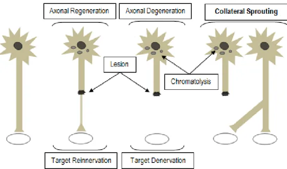
Figure 6 -Nerve regeneration mechanisms.
Figure 7 - Reinnervation mechanisms of denervated targets.
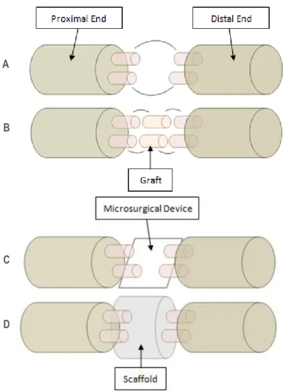
Figure 8 - Nerve repair strategies.
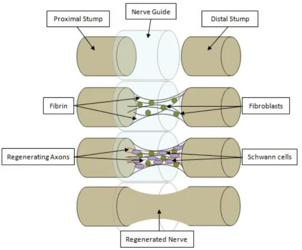
Figure 9 - Axonal regeneration in a nerve guide tube.
Figure 10 - Conventional lithography.
Figure 11 - Nanoimprint lithography and molding techniques.
Figure 12 - Cell patterning approaches.
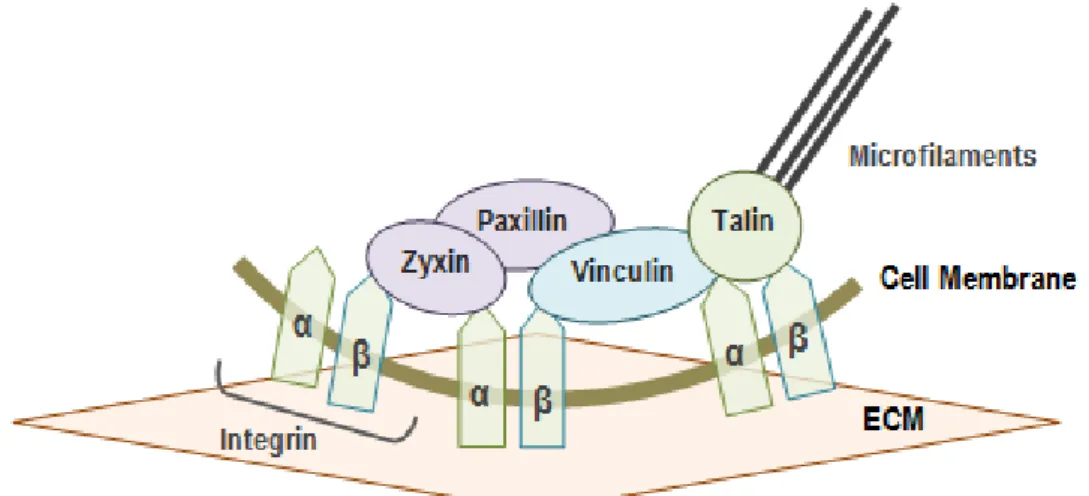
Figure 13 - Focal adhesion complex.
Figure 14 - Basic nanotopographic geometries.
Figure 15 - Bifurcation approach.
Figure 16 - Peripheral neural electrode-based interfaces.
Figure 17 - Designs for axonal isolation.
11 Figure 19 - Axonal channels.
Figure 20 - Contact angle-interface.
Figure 21 - FlexiForce® force sensor.
Figure 22 - Paper clips-based “hot embossing” setup. Figure 23 - Bonding process.
Figure 24 - LIVE/DEAD pictures.
Figure 25 - Contact angle measurements of cyclic olefin copolymer and polydimethylsiloxane for different exposure times of air plasma treatment.
Figure 26 - Resistance measurements performed with the Flexiforce® sensor.
Figure 27 - Calibration curve: Linear regression of electrical conductance was calculated inverting resistance values of Figure 26.
Figure 28 - Scanning emission microscope pictures of channels in polydimethylsiloxane cast.
Figure 29 - Scanning emission microscope pictures of imprinted nanopatterns on the surface of the cyclic olefin copolymer.
Figure 30 - Amount of deoxyribonucleic acid measured in different cell culture substrates (one biological experiment).
Figure 31 - Adenosine triphosphate amounts measured in different cell culture substrates. Samples used were from the same biological experiment performed for the deoxyribonucleic acid assay (Figure 30).
Figure 32 - Amount of deoxyribonucleic acid measured in different cell culture substrates (biological triplicates).
Figure 33 - Deoxyribonucleic acid assay results from different media conditions (one biological experiment).
12
Figure 34 - Concentrations of adenosine triphosphate detected from different media conditions. Samples used were from the same biological experiment performed for the deoxyribonucleic assay (Figure 33).
Figure 35 - Deoxyribonucleic acid concentrations measured in different media conditions (biological triplicates).
Figure 36 - F11 cells stained with Phalloidin 488 and 4’,6-diamidino-2-phenylindole in different cell culture substrates.
Figure 37 - F11 cells stained with Phalloidin 488 and 4’,6-diamidino-2-phenylindole in different media conditions.
Figure 38 - Scanning emission microscope pictures of polydimethylsiloxane channels in different baking conditions.
Figure 39 - Nanotopographic device bonded in optimal conditions.
Figure 40 - F11 cells stained with Phalloidin 568 and 4’,6-diamidino-2-phenylindole in the nanotopographical device (after 2 days of culture).
Figure 41 - Bright field picture showing alignment of “Ys” imprinted on cyclic olefin copolymer and polydimethylsiloxane channels, forming axonal channels.
13
LIST OF TABLES
Table 1 - Generalized neural cell response to nanotopographical features.
Table 2 - Cyclic olefin copolymer and polydimethylsiloxane bonding trials combining different techniques (ultraviolet and air plasma) and exposure times.
14
ABBREVIATIONS
AAOP - American Academy of Orthotists and Prosthetists ANOVA - Analysis of Variance
APTES - (3-Aminopropyl)trimethoxysilane ATP - Adenosine Triphosphate
BDNF - Brain-derived Neurotrophic Factor COC - Cyclic Oleofin Copolymer
CNS - Central Nervous System DAPI - 4’,6-Diamidino-2-Phenylindole DLB - DNA Lysis Buffer
DMEM - Dulbecco’s Modified Eagle Medium DNA - Deoxyribonucleic Acid
DRG - Dorsal Root Ganglia EBL - Electron Beam Lithography ECM - Extracellular Matrix
EDTA - Ethylenediamine Tetraacetic Acid EthD-1 - Ethdium Homodimer-1
ETOH - Ethanol FA - Focal Adhesion FBS - Fetal Bovine Serum
FES - Functional Electrical Stimulation FGF - Fibroblast Growth Factors FINE - Flat Interface Nerve Electrode FSK - Forskolin
GIA - Global Industry Analysts, Inc.
LIFE - Longitudinal Intrafascicular Electrode MAG - Myelin-associated Glycoprotein MEA - Multielectrode Array
15 MT - Microtubule
NG - Nerve Guide
NGC - Nerve Guidance Channel NGF - Nerve Growth Factor NIL - Nanoimprint Lithography NT - Neurotrophin
NTE - Neural Tissue Engineering PC - Polycarbonate
PBS - Phosphate Buffered Saline PDMS - Poly(dimethylsiloxane) PNI - Peripheral Nerve Interface PNS - Peripheral Nervous System PS - Polystyrene
RT - Room Temperature SC - Schwann Cell
SEM - Scanning Emission Microscopy SPL - Scanning Probe Lithography TCT - Tissue-culture-treated
TIME - Transverse Intrafascicular Multichannel Electrode UEA - Utah Electrode Array
USEA - Utah Slanted Electrode Array UV - Ultraviolet
VEGF - Vascular Endothelial Growth Factor WD - Working Distance
16
CHAPTER 1 - INTRODUCTION
1.1. Project Motivation
According to the American Academy of Orthotists and Prosthetists (AAOP), in 2020, 2.4 million people will have an amputation and use prostheses [1]. The most common are the limb amputations, usually caused by vascular complications (Dysvascularity) [2], from issues such as diabetes, a rising incidence disease in developed countries [3].
Prostheses are medical artificial substitutes for replacement of missing or amputee body parts, but its progress has been slow. Recently, developed limb prostheses have been made clinically available for motor rehabilitation of amputees [2]. Advances in components or materials, socket fitting techniques between the residual limb (stump) and the prosthesis, and power sources [3] have contributed to better functionality, efficiency, comfort and lifelike appearance (cosmetically pleasing) [4, 5] of upper and lower limb prostheses.
Although the quality of the interface between the socket and the stump have been greatly improved in the past three decades [4], low dexterity, motility and limited sensory feedback [3] have motivated the substitution of passive and battery powered prostheses. The latest developments are towards body powered prostheses or neuroprostheses, designed to replace lost or impaired motor or sensory functions by communicating directly or indirectly with the nervous system [2].
Compared with human limbs, limb neuroprostheses still have limited performance, mainly due to limitations in the creation of neural interfaces able to provide proper bidirectional connection between the cells of the peripheral nervous system (PNS) of the amputee and the neuroprosthesis. Selectivity is the capacity of a peripheral nerve interface (PNI) to access specific types of neurons, like sensory, motor or autonomic neurons. This constitutes the greatest challenge to develop clinically accepted PNIs suitable for integration with neuroprostheses [2].
17
A new report by the Global Industry Analysts, Inc. (GIA) reveals that the Global Orthopaedic Prosthetics Market will reach 14.6 billion euros by 2015, especially due to the development of advanced devices [6].
Indeed, innovations in microfluidics, a recent technology using microscale channels to manipulate fluids in a controlled manner at the nanoliter scale has proved to have potential to significantly contribute with three main emerging biomedical areas, namely neuroengineering, nanomedicine and neural tissue engineering (NTE) for the construction of advanced PNIs [7, 8].
Neuroengineering (or neural engineering) has developed a wide range of highly sophisticated stimulating and recording electronic interfaces with different levels of invasiveness and selectivity [2] [9]. At the same time, NTE has created artificial structures and scaffolds that mimic the complexity of nervous tissue [8] [10] and can be incorporated into the PNIs to promote tissue regeneration of injured neurons after amputation [9].
Furthermore, it is known that the macro (>1 mm, overall shape of the scaffold), micro (1 µm-1 mm, cellular level) and nanostructural (<1 µm, subcellular/molecular level) surface properties are important for cell-scaffold interaction [11]. For that reason, the application of nanotechnology to medicine resulted on the “Nanomedicine” or “Nanobiomedicine” field and has been contributing toward the creation of new structures with dimensions on the nanoscale that are useful for tissue engineering purposes [8] [12-14].
Indeed, as different types of neural cells respond positively to different nanotopographical features, which are similar to their natural cellular microenvironment [8], the ability to precisely control the cell response using nanotopography will largely improve the design and development of PNIs.
However, further studies regarding nanoscale features and structures which control neurite growth are still necessary to allow the development of clinically useful platforms for the successful regeneration or replacement of PNS structures [8]. Although the microfluidics field is still at an early stage of development, microfluidic devices are increasingly being used for neuroscience
18
research and can also be implantable as PNIs, providing a future direction to the new field of neurofluidics [15] (Figure 1).
1.2. Project Aims
The aim of this project is to fabricate and optimize a microfluidic device that can be used as an in vitro model to analyze neural cell response to nanotopography. Thus, if cells reveal preferential growth over certain nanotopographical features, scaffolds with optimal surface topography can be fabricated. Moreover, if different neural cell types have specific growth preferences, scaffolds can be designed with the purpose of selective guidance and physical segregation of axons based on their type and function. The in vivo integration of these scaffolds with PNIs will then improve selectivity as well as enhance the control over the neuroprosthesis. For instance, motor axons can be nanotopographically guided to electrodes used to electrically stimulate them,
Figure 1 - Recent advances in Neuroengineering, NTE and Nanomedicine fields have been contributing together for the enhancement of PNIs able to be integrated in neuroprostheses. Neurofluidics is a new field that results from the applications of microfluidics to neurobiological research. Future innovations are likely to depend on the strong interaction between all these areas. NTE: Neural Tissue Engineering; PNIs: Peripheral Neural Interfaces.
19
whilst sensory axons are guided to electrodes for signal recording (Figure 2). In this way, the main goals of this project are described below:
1. To fabricate a device suitable for assessing preferential axonal outgrowth of neural cells on certain nanotopographical features;
2. To optimize the design and fabrication techniques of the nanotopographic device, according to cell response.
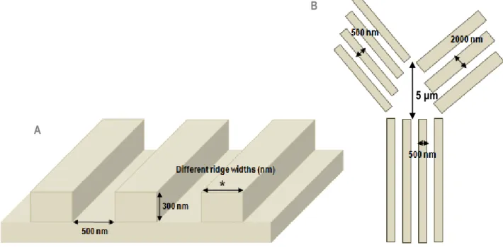
To achieve the described objectives, the strategy consisted of fabricating “Y-shaped” nanotopographic patterns on the surface used for neural cells culture and analysing the behaviour of the growing axons. As they encounter the bifurcation, monitoring which pattern they choose (Figure 3B) provides insight into topographical preference. The groove dimensions of the nanograting pattern are constant in all the “Y” structure. However, different ridges widths
Figure 2 - Specific nanotopographical features on the surface of PNIs will promote guidance, growth and physical segregation of neuronal subtypes allowing a selective control: Electrode 1 promotes signal recording of sensory neurons and electrode 2 induces electrical stimulation of motor neurons. PNIs: Peripheral Neural Interfaces.
20
were tested (Figure 3A). In addition, a microfluidic platform was used to provide isolation of PNS axons from cell bodies and dendrites in order to facilitate the analysis of the axonal response.
The F11 hybridoma, a dorsal root ganglion-derived cell line, was chosen as model to investigate the response of nociceptive sensory neurons to nanotopographical guidance cues. It was shown previously that F11 axons grow along nanopatterns of 500 nm ridge width [16], so the initial part of the “Y” presents a ridge of 500 nm, while different combinations of ridge widths between 500 nm and 2000 nm were used to test their choices (Figure 3C).
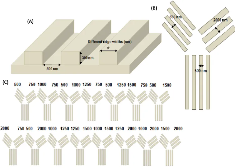
Figure 3 – Nanotopographical patterns were imprinted on the cell culture substrate: (A) Dimensions of the grooves are constant (width of 500 nm and depth of 300 nm) and different ridge widths were studied; (B) The right and left parts of the “Y”-bifurcation had different ridge width constant values between 500 nm and 2000 nm; (C) Different combinations of ridge width values for the bifurcation were used in consecutive imprinted “Ys” on the surface of cell culture.
(A)
(B)
21
CHAPTER 2 – “STATE-OF-ART”
2.1. Peripheral Nerve Injury and Regeneration
The human nervous system can be anatomically divided into the central nervous system (CNS) and the PNS [17]. The CNS is composed of the brain and the spinal cord, and the PNS contains the peripheral nerves [8]. The neuron is the basic structural and functional unit of the nervous system and each one consists of a cell body (soma) and its extensions (axons and dendrites) [17]. Dendrites transmit electrical signals to the cell body and axons conducts impulses away from the soma [18]. The cell bodies of the sensory neurons are located near the spinal cord in the dorsal root ganglia (DRG) or in cranial ganglia, while the cell bodies of the motor neurons are inside the CNS, spinal cord or brainstem [19]. Axons extend into the body toward their target organs,
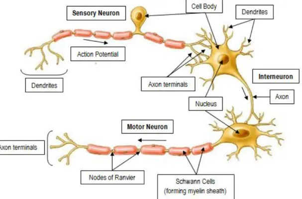
Figure 4 – Basic neuron types: Sensory neurons are unipolar - the axon branches to connect sensory receptors to the spinal cord or brain; motor neurons and interneurons are multipolar, having several dendrites and one axon. The nucleus and the cytoplasm constitute the cell body (soma) of the neuron; dendrites receive and process electrical stimuli from other neurons and axons transmit the action potentials to the axon terminals. SCs form myelin around the axon and line up along it with distinct gaps, called nodes of Ranvier (adapted from [21]). SCs: Schwann Cells.
22
bundling together en route to form peripheral nerves [20].
Sensory (or afferent) neurons transmit electrical signals from sensory receptors (e.g., in skin, eyes, etc) toward the CNS and motor (or efferent) neurons send electrical signals away from the CNS to muscles or glands (Figure 4) [21]. A single peripheral nerve is filled with several sensory and motor axons, myelinated by Schwann cells (SCs), supported by fibroblasts, and protected by the epineurium (Figure 5) [22].
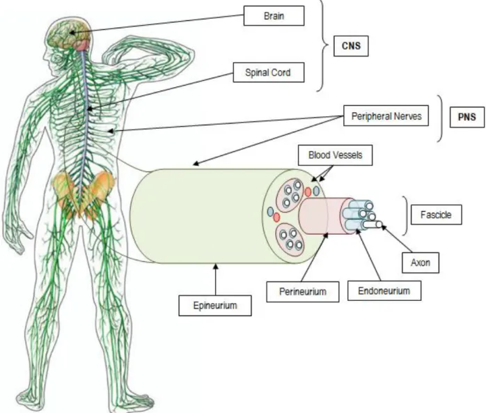
Figure 5 - Anatomy of human nervous system: CNS, composed of the brain and the spinal cord, and PNS constituted by the peripheral nerves. Individual axons and their SCs myelin sheaths are surrounded by connective tissue with collagen fibers, called endoneurium; the perineurium, a connective tissue formed from layers of flat cells and collagen, forms the fascicles. At last, the epineurium is composed of loose fibro-collagenous tissue and binds fascicles into a nerve trunk, vascularised by surrounding blood vessels (adapted from [2] and [22]). CNS: Central Nervous System; PNS: Peripheral Nervous System; SCs: Schwann Cells.
23
The response to axotomy, or a lesion in the axon, is different in the CNS and PNS [23], namely the nerve degeneration and regeneration mechanisms [8] [24]. The peripheral nerve injuries can result from ischemic (due to the restriction in blood supply), chemical, mechanical, or thermal factors, leading usually to the transection of the axons [23]. However, the capacity of nerve regeneration [8] as well as the intensity and duration of the neural response depends on the severity of the injury, distance between the lesion and the cell body, type of neuron, and age [2]. According to the type and extent of damage to the nerve and surrounding connective tissue, a neuron injury is classified in neuropraxia (nerve remains intact but signalling ability is damaged), axonotmesis (nerve remains intact but with interruptions in impulse conduction) and neurotmesis (injury in axon and surrounding connective tissue) [2].
The molecular mechanisms involved in axonal regeneration are complex and interactions between molecules are still not completely clear [25]. However, after axotomy, the cytoskeleton of the axonal portion that is disconnected from the cell body (distal end) suffers degradation due to calcium-dependent protease activity and separation from the metabolically active cell body, leading to membrane rupture, known as anterograde or Wallerian degeneration. A short distance of the proximal end may also degenerate (retrograde degeneration), but usually survives [8] [25].
Consequently, in the distal end, SCs, previously wrapped around the axon, release myelin lipids (demyelination), and begin to remove myelin and axonal debris (Figure 6A). Simultaneously, genes for myelin-specific proteins are downregulated in SCs. In particular, as myelin-associated glycoprotein (MAG) inhibits peripheral axon regeneration, SCs adopt a non-myelinating phenotype, producing myelin MAG-free to promote axonal growth [2]. Moreover, SCs also secrete cytokines that attract macrophages to complete myelin and axonal clearance [19]. Mast cells around injury site produce histamine and heparin, increasing vascular permeability to attract more macrophages and also contribute to the degradation of myelin debris [8] [18].
After debris clearance, specific growth factors for axon regrowth, or neurotrophic factors, such as neurotrophins (NTs), neuropoetic cytokines and
24
fibroblast growth factors (FGFs) are released. Nerve growth factor (NGF), neurotrophin-3 (NT-3), and brain-derived neurotrophic factor (BDNF) are NTs produced by SCs to promote axonal regeneration [19]. NGF and vascular endothelial growth factor (VEGF) are also released by mast cells. Tropomyosin-related kinase (Trk) and low affinity receptors (such as p75) in the axonal membrane are activated by NTs, triggering axonal outgrowth. Thus, regeneration begins at the proximal end, where several sprouts (growth cones) are emitted, usually from the nodes of Ranvier, and continues toward the distal end [8] [26].
A
B
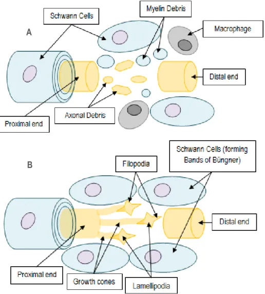
Figure 6 – SCs play an important role in axonal regeneration: (A) 1. Demyelinated damaged axon, 2. Begin clearance of axonal and myelin debris; 3. Produce myelin MAG-free; 4. Release cytokines to attract macrophages; (B) 5. Secrete neurotrophic factors to induce growth cones emergence and development; 6. Form Bands of Büngner with a specialized ECM essential for axon survival and migration (adapted from [25]). SCs: Schwann Cells; MAG: Myelin-associated Glycoprotein; ECM: Extracellular Matrix.
25
Filopodia and Lamellipodia are the mobile path-finder parts of the growth cone. When filopodia encounter the substrate, membrane receptors bind to extracellular matrix (ECM) molecules, re-organizing cytoskeleton and leading growth cone protrusion [25]. In addition, macrophages produce cytokines that induce SCs to proliferate and form columns of SCs within the remaining tubule of lamina basal. This forms the Bands of Büngner, creating a tubular channels that support [2] and guide regenerating axons to grow to the final targets (Figure 6B) [19] [27]. In the absence of a guide, disperse axonal sprouts and connective tissue form a neuroma (an abnormal growth of nerve tissue) [2].
There are natural mechanisms to compensate for an unsuccessful reinnervation of target organs by regenerating axons, namely the axonal collateral sprouting and the adaptability of the CNS [2].
Collateral sprouting of undamaged axons has different characteristics from regenerative axonal sprouting in response to the absence of other axonal innervations in the same target tissues and results from local secretion of local neurotrophic factors by the denervated cells (Figure 7). Also here, SCs play an important role guiding axonal sprouts to denervated areas. Terminal sprouts emerge from the axon terminals (terminal sprouting) and the nodal sprouts (collateral sprouting) come up from the nodes of Ranvier [2].
However, neither target reinnervation by typical axonal regeneration nor by collateral sprouting promote the full restoration of sensory and motor functions [19]. The diameter, conduction velocity and excitability of regenerated axons remain lower than normal axons for a long time and consequently recovery of reinnervated organs is incomplete [2].
Furthermore, some factors contribute to poor functional recovery after nerve injury: damage of cell body; inability of axonal growth, due to nerve lesion or diseases; and poor specificity of reinnervation by regenerating axons [2].
For that reason, NTE has been developing new strategies for axonal regeneration after injury and several studies in vivo show successful recovery of neuronal functions [18].
26
2.2. Tissue Engineering Strategies for Peripheral Nerve Repair
The complexity of the physiology of the nervous system constitutes a challenge in finding effective treatments for nerve repair. The complete transection of the nerve is the most severe injury [8], but according to the size of the lesion, there are different treatment options for peripheral nerve repair [23] [28].
For small size lesions (few millimetres in length), surgical reconnection of the injured nerve ends (coaptation [8]) is the current clinical treatment [23] [29]. For large size lesions, autologous nerve graft (autograft) from another site in the body or another individual (allograft) is used to fill in the lesion gap and constitutes the gold standard therapy [19].
However, the use of grafts includes risks of morbidity and loss of function at donor site [8], and requires multiple surgeries [23]. Moreover, donor nerves are often few and small [19] and structural and functional restoration of the
Figure 7 - Axotomized neurons suffer changes in their bodies (chromatolysis), but axonal regeneration usually occurs and target is reinnervated. In case of target denervation, collateral sprouts are induced to grow towards the free target (adapted from [2]).
27
injured nerves is incomplete. So, to solve these problems, alternative tissue engineering strategies are being developed for PNS repair [18].
NTE is composed of three main parts: the cells (neurons and supporting glial cells - the SCs in PNS), the scaffolds (to support cell growth, differentiation and guidance [19]), and the proteins (such as neurotrophic factors and ECM)
A
B
C
D
Figure 8 – Nerve repair strategies: (A) Coaptation of proximal and distal ends of damaged axons; (B) Autograft or allograft connects proximal and distal ends; (C) Microsurgical devices promotes axonal cutting (by using a nanoknife or a microbeam laser, and an electrical field for splicing of the ends) and stimulation, by using arrays of electrodes; (D) Scaffolds, fabricated with natural or synthetic polymers, recreate ECM native properties. Besides these strategies, ex vivo genetic modification of grafted cells may be a feasible approach for additional axonal growth support (adapted from [29]). ECM: Extracellular Matrix.
28
[8]. However, due to electrically excitable nature of neurons, NTE strategies can be separated in four categories: Axonal guidance devices (using tubular scaffolds), cell population recovery (usually by stem cell transplantation or SCs graft [19]), drug delivery (of neurotrophic factors, anti-inflammatory and neuroprotective agents [30]), and electrical stimulation.
Although the combination of these approaches seems to be a feasible solution to nerve repair [23], the typical NTE approach consists in reconnecting damaged axonal ends and consequently achieving target reinnervation. This is done by implanting in vivo the artificial scaffolds and substrates that will guide regenerating axons (in a similar way to the Bands of Bϋngner) (Figure 8) [19].
For small injury gaps, nerve guides (NGs) that are basically tubular artificial scaffolds are placed across the lesion gap in order to guide axonal growth [19], bind the two portions of the damaged axon and create an isolated, well-controlled regeneration environment (Figure 9) [23].
For large gaps, hollow tubes, or nerve guidance channels (NGC), are used [19] because porosity plays an important role in the nerve regeneration process, allowing the migration of cells as well as medium or blood vessel influx into the scaffold [23].
Current strategies for large nerve defects have proved to be alternatives to the autologous nerve grafts, promoting and accelerating functional recovery. However, this recovery is still not complete. For that reason, recent research in vitro is focused on developing improved scaffolds that better mimic ECM [8].
Indeed, topographic cues provided by ECM have already proved to influence cell behaviour [8]. In addition, nanotechnology allowed the development of nanotopographic substrates that can be used to induce axonal outgrowth and guidance during neuronal culturing [8] [31]. Thus, the incorporation of nanotopographic surfaces into scaffolds has the potential to physically guide regeneration of nerve across lesions [18].
29
2.3. Nanotechnologies and Neural Cell Response to Nanotopography
Cells in vivo experience a complex environment with nanotopographies provided by the ECM. Thus, a promising route is to recapitulate nanotopographical cues in vitro in order to steer and control protein and cellular interactions [8] [32]. With the advancement of micro- and nanofabrication technology, several techniques have been used in fabricating groove-like patterns on a variety of substrates [8] [33].
Figure 9 - Axonal regeneration in a NG tube: Fluid phase: fluid and cytokines (including neurotrophic factors) enters into the NG; Matrix Phase: a fibrin matrix is formed and supports the fibroblasts, SCs and axons – Cellular phase; Axonal phase: SCs myelinate axons that are guided by Bands of Bϋndger towards their targets; the regenerated nerve is usually thinner in the middle of the bridge (adapted from [19]). NG: Nerve Guide; SCs: Schwann Cells.
30
Although applications of nanotechnology in neuroscience are only in the early stages of development, partially because of the complexities associated with interacting with neural cells, several researchers have shown in vitro that surface topography plays an important role in axonal outgrowth guidance as well as SCs activity enhancement. In particular, nanoscale patterned substrates constitute topographical cues and promote better nerve regeneration [34].
2.3.1. Nanofabrication Techniques
As described in a review by Gates et al. [35], new nanofabrication techniques have been developed in the last few decades [35] [36]. Although lithography, namely photolithography (mainly using UV light) and particle beam lithography (usually electron beam lithography, EBL), are the dominant conventional techniques for nanofabrication (Figure 10), several different approaches, such as molding, embossing and printing have been developed for patterning nanoscale structures. Molding and embossing techniques can be divided into two categories depending on the mold type, hard or soft (elastomeric). Molding requires curing a precursor against a topographically patterned substrate, while embossing (or imprinting) transfers a mold with a structured topography into an initially flat polymer film (Figure 11). For example, nanoimprint lithography (NIL) or “hot embossing” results from a pressure-induced transference of a topographic pattern from a rigid mold, usually silicon (Si), into a thermoplastic polymer film heated above its glass-transition temperature (Tg) [35].
Printing techniques (such as microcontact printing, µCP) are also useful in nanofabrication, by transferring a material onto a substrate from a topographically patterned stamp. Moreover, scanning probe lithography (SPL) is a versatile method that allows deposition of clusters of atoms and molecules onto a surface in a well-defined pattern. Edge lithography is another promising approach that uses topographical changes in the edge of patterns, by
31
selectively removing or depositing material at the edges to create a larger feature in the vertical direction [35].
All these techniques use “top-down” approaches to patterning structures (that consist on the incorporation of smaller-scale details into micro/macroscopic materials [37]). Self-assembly is a “bottom-up” nanofabrication strategy and consists on the aggregation of components using covalent and/or non-covalent bonds. These components can aggregate spontaneously (non-templated self-assembly) or interacting with external forces or spatial constraints (template self-assembly) [31] [35]. In addition, different nanoscale topographies can be produced by using chemical techniques, such as chemical etching, polymer demixing, and phase separation as well as electrospinning (application of a high voltage to a flowing viscous polymer
Figure 10 - Conventional lithography (A-E): Photolithography uses UV light and a mask to selectively develop the photoresist (A) while EBL creates nanopatterns directly on the photoresist (B) (adapted from [35]. UV: Ultraviolet; EBL: Electron beam Lithography.
32
solution) [11] [38]. Several types and combinations of materials have also been tried, such as glass, metal oxides, natural and synthetic polymers [8] [35] [36].
2.3.2. Contact Guidance on Nanopatterns
In general, nanotopography can induce two main neural cell responses: cell patterning or contact guidance [39]. Cell patterning consists in the control of the cell position on a surface. For this purpose, there are two main types of approaches: topographical patterning, by using substrates with patterns of shape or texture, and physicochemical patterning, by applying patterns of chemical adhesion or patterns of electrical or physical force on cultured cells [23]; or the combination of both strategies (Figure 12) [40].
Cell patterning has been especially important in neural networks mimicking for CNS repair purposes, by regulating mainly collective cell functions, such as cell adhesion, proliferation and differentiation. Contact guidance, on the other hand, is being crucial in PNS regeneration.
Figure 11 - Molding technique (A-C): Usually a PDMS prepolymer is cured against a patterned master to create nanotopographies on the surface of the PDMS substrate; NIL (D-F): A rigid master transfers topographic nanopatterns on the thermoplastic polymer film by heating the polymer above Tg and applying pressure on the surface (adapted from [35]).
33
The mechanism of contact guidance was described by Weiss in 1934 and refers to the phenomenon that neurites grow on nanopatterns, adjust their orientation and align along those patterns [33]. Axons and dendrites are called in vitro collectively neurites and axonal neurite outgrowth can be guided by the geometry and orientation of the surface topographical cues [41] [42].
Indeed, Bettinger et al. [36] showed that contact guidance is an important component in efficient growth cone formation, motility and guidance. However, the molecular mechanisms of cell sensing to nanopatterns, the factors, and the cellular effects are not completely understood [33] [39] [42].
A
B
C
Figure 12 – Cell patterning approaches: (A) Topographical features are grooves with different dimensions, for example; (B) Chemical features results of specific spatial distributions of different biomolecules; and (C) electrical features consists on the application of electrical potential or charge on the surface, for instance (adapted from [40].
34
2.3.3. Cell-surface Interactions at the Nanoscale
Cells are sensitive to nanostructures and it is possible to control and manipulate their behaviour in vitro and in vivo by fabricating surfaces with nanotopographical features [8]. Although it had been proposed that topography may induce changes in protein absorption from the cell culture media, observations proved that cell sensing of topographic is practically independent of the differences in protein adsorption behavior. Cell sensing and response to topography occurs due to a cell-adaptation mechanism, independent of absorbed proteins. Although the molecular mechanisms involved are not completely clear, during adaptation the topographic pattern determines the regulation of specific cell functions [39].
Several studies show that cell adhesion to the surface results from specific binding interactions between transmembrane receptors (integrins) and their ligands absorbed onto the surface. The integrin is a heterodimer of α and β units. Different combinations of these units result in different types of integrins which bind selectively to specific ligands. This binding process induces a change of integrins conformation: cytoplasmatic proteins such as talin bind to the cytoplasmatic tails of integrins inducing other integrins to bind, originating a cluster of integrins; this clustering causes the recruitment of several different types of proteins, such as focal adhesion enzymes (e.g. kinase and Src kinase), adaptor molecules (paxillin, that binds to other proteins), and α-actinin (that binds to the actin cytoskeleton). This assembly of proteins forms the focal adhesion (FA) complex (Figure 13) [43]. This dynamic multimolecular assembly allows mechanical force to transfer between the inside of the cell and the surface of the substrate, where cellular tensile forces are balanced with compressive forces in the substrate [8].
FAs are consequently responsible for cell shape but also are signalling complexes, which initiate cascades of signals that control gene expression. Thus, during cell interaction with the surface, the degree of cell adhesion determines fundamental cell functions, such as survival, proliferation, migration, differentiation and apoptosis [8] [41]. In this way, by using surfaces with
35
nanofeatures it can be possible to control the FA assembly and consequently cell fate and functions [8].
In particular, in vivo and in vitro experiments indicate that topographical cues regulate contact guidance. Initially, neurites emerge from the cell body, grow and find their way toward specific targets (neurite path finding). However, both neurite initiation and extension depend on the formation and stabilization of FAs [44]. One primary neurite becomes an axon and begins its fast growth, while the remaining neurites develop into dendrites [45] [46]. Then, neurites probe surrounding environment with membrane projections, the filopodia, allowing a feedback detection mechanism for specific cues [41] [45]. Thus, the filopodia constitutes a mechanosensory system that detects physical or chemical cues on the surface [41]. These cues are converted into biochemical response (mechanotransduction), regulating gene expression [41] [47].
Although the molecular basis of mechanotransduction is complex, it has been reported that cells respond differently to topographic substrates depending on cell type, feature size, distribution and geometry or physical properties of the substrate material [8] [11] [36] [41].
Figure 13 – FA complex: Integrins bind to proteins of the ECM and intracellular proteins link integrins to cell cytoskeleton. This phenomenon also occurs when cells interact with topographical cues (similar to the native ECM) on the surface. F-actin filaments (microfilaments) and microtubules (MTs) are the dynamic cytoskeletal polymers. Together with FAs, they are responsible for promoting shape change and locomotion and consequently axon outgrowth and guidance (adapted from [8]). FA: Focal adhesion; ECM: Extracellular Matrix.
36
2.3.4. Neural Cell Response to Nanotopographical Features
Based on the pattern, topography can be classified in isotropic or anisotropic [11] [39] [48]. In general, anisotropic topographies, such as grooves and ridges, have been used to study cell alignment (or orientation), while studies with isotropic topographies, such as evenly or randomly distributed pits or protusions, have been focused on collective cell behaviors [39]. Moreover, Bettinger et al. [36] defined three basic nanotopographic geometries used on in vitro research, namely nanogratings, nanopost arrays, and nanopit arrays (Figure 14). However, other regular and irregular nanoscale features have been used [39], such as spheres, particles, fibers, and others [41].
A
B
C
Figure 14 - Basic nanotopographic geometries: (A) Nanogratings, (B) Nanopit arrays; (C) Nanopost arrays (adapted from [36]).
37
Although the comparison of various isotropic topographies may currently be difficult because of diversities in topographic size, shape, uniformity, or even chemistry [39], many studies have demonstrated neurite outgrowth, alignment or guidance on these surfaces (Table 1) [16] [38] [44] [49-63]. Even though several cell types have been used as models in neural repair approaches, such as neuronal cell lines, primary cells, stem cell or cancer cells (like neuroblastomas) [33], only cell types usually studied for PNS repair purposes were considered in this literature review.
In general, researchers showed that cells cultured on nanogratings presented lower proliferation rates than cells cultured on flat substrates. However, nanogratings have shown to enhance the cell adhesion into several geometrical combinations, while nanoposts and nanopits generally reduce initial cell attachment. For instance, neurites extending from PC 12 cell line cultured on nanogratings have shown enhanced alignment and extension, while reduction of spreading was observed on nanoposts and nanopits [36]..
Moreover, FA formation occurs predominantly on the ridge structures and the width of the FAs is determined by the width of the ridge [64]. Consequently, aligned axonal outgrowth was preferentially observed on ridge edges and elevations rather than in grooves. In these cases, both cell shape and cytoskeleton displayed directional organization [33] [39].
Thus, nanograting substrates can be used to study contact guidance and migration in vitro. Nanopost or nanopit substrates can be used to study the filopodia dynamics, FA formation, and other cytoskeleton functions in a controlled manner [36].
Although many of the studies are still qualitative and sometimes produce conflicting results with similar nanotopography [65], results suggest that the topographical structures and chemical properties of the scaffold must be optimized for each cell type [33]. However, more work needs to be done in order to understand if there is a preferential outgrowth of individual neurites over certain nanotopographical features.
38
Table 1 – Generalized neural cell response to nanotopographical features. PC12: Pheochromocytoma cell line of the rat adrenal medulla; DRG: Dorsal root ganglion; F11: Hybridoma of mouse neuroblastoma cell line N18TG-2 with embryonic DRG neurons; NIL: Nanoimprint lithography; μCP: Microcontact printing; EBL: Electron beam lithography.
39
2.3.5. Selective Neurite Outgrowth and Guidance
A review of the literature shows that additional work has to be done on single-cell analysis of neurite outgrowth and guidance over different nanogratings. Table 1 indicates that several researchers have achieved contact guidance of many cell types on different types of nanofeatures. Some of them have even tried to compare cell response to different feature dimensions or types, but none tested the preferential response of individual neurites [66].
Fozdar et al. [67] have already developed competition assays in order to assess the ability of topography to attract axonal formation based on feature size and shape. A grid with arrays of nanopits and nanogratings was constructed and single hippocampal neurons (CNS) were micropositioned in gaps between neighbouring topographies. Results suggest that axons prefer nanoscale (300 nm) over microscale (2000 nm) and holes over lines for a given feature size.
Based on these results, the use of a bifurcating approach in order to create a nanofeature choice system seemed to be an alternative and a feasible approach. Thus, neurons could be placed near to the “Y-shaped” nanogratings and axons would grow over their preferential ridge dimensions.
However, the bifurcation approach was not new. Curley and Moore [68] had already constructed a dual hydrogel “Y” model in order to promote neurite outgrowth in a 3D environment.
In particular, Wieringa et al. [69] in 2010 had shown that the microchannels bifurcating approach was able to promote separation of growing neurites. However, this separation was not based on topography of the surface, but based on physical-space constraints.
Wieringa et al. [16] in 2012 introduced the F11 neural cell line as an in vitro model for PNS regeneration purposes and cultured F11 cells on various nanograting substrates. These results indicated that the F11 cells are sensitive to nanotopographical features. Based on that, F11 cell line seemed to be a
40
feasible in vitro peripheral sensory neuron model for nanotopographical guidance.
Ferrari et al. [50] had already tested neurite outgrowth of PC12 cells over six different nanogratings transferred on COC films using NIL (ridge width of 500 nm, depths of 350 nm, and groove widths of 500 nm, 750 nm, 1000 nm, 1250 nm, 1500 nm, and 2000 nm). For that reason, and according to the results showing preferential axonal growth over the ridges, the implementation of ridges with widths of 500 nm, 750 nm, 1000 nm, 1250 nm, 1500 nm, and 2000 nm in the “Y-shape” model seemed to be a feasible approach (Figure 15A).
Thus, several combinations of different ridge width values could be tested by using consecutive “Ys” on the surface of the cell culture substrate. Preferential growth and selection of F11 axons over certain feature sizes could be then evaluated. For instance, axons could choose between 500 nm and 2000 nm of ridge width (Figure 15B).
Furthermore, it was already shown that axons are able to cross ridges or grooves [39]. Goldner et al. [59] showed that DRG neurites can successfully bridge micropatterned grooves (200 μm plateau width). In addition, Fozdar et al. [67] also concluded that neurons positioned in close proximity to topography (<30 μm) recognized and responded to the topography, regardless of feature dimensions. Thus, the maximal gap of 5 μm between the right and left parts of the bifurcation is suitable for axons to choose the right or left patterns without influencing their decisions.
Based on the nanotopographical preferences of each neural cell type, nanofabrication techniques might be applied to provide topographical guiding structures in order to manipulate the axonal outgrowth.
As sufficient electrical recording or stimulation is achieved only when a neuron is located directly on the top of the electrode, these topographical guiding structures might be incorporated into an implantable electrode to improve selectivity and signal transmission across PNIs [40] [70].
41
2.4. Neuroengineering Solutions for Selectivity on Peripheral Neural Interfaces
For amputee rehabilitation purposes, the three main approaches of neuroengineering are: restoration (control and repair function of remaining injured structures), replacement (substitute impaired structures with artificial ones, controlled by another natural and functional neural or muscular structures) and neuromodulation (train CNS in order to induce plasticity through artificial substitutes) [71].
Neuroprostheses link the PNS with electronic or robotic devices and have been widely used not only for replacement purposes, but also to restore the sensory and motor functions in disable patients.
A
B
Figure 15 – “Y-shaped” bifurcation approach: (A) Dimensions of the grooves are constant (width of 500 nm and depth of 300 nm), different ridge widths are applied; (B) The right and left parts of the bifurcation of each “Y” have different ridge width constant values between 500 nm and 2000 nm; different combinations of ridge width values are used in consecutive “Ys” on the surface of the cell culture substrate. The maximal gap between the right and left parts of the bifurcation is 5 μm and growing axons need to cross it in order to choose their preferential nanopatterns.
42
According to the Helmholtz’s reciprocity theorem, electrodes detect the bioelectrical activity from active neurons (recording) as well as inject electrical current in order to induce activity in neurons (stimulation). Thus, functional electrical stimulation (FES) systems that are basically arrays of electrodes have been implemented on neuroprosthetic devices to interact with neurons and stimulate them to regenerate [20]. FES systems constitute then a bidirectional interface, allowing nerve stimulation and neural signal recording, and also work as feasible PNIs [2], by connecting peripheral nerves to prosthetic devices [72].
PNIs are usually implanted around, between or within a peripheral nerve or spinal root in order to reduce tissue resistance and to increase stimulus intensity or ensure consistent recordings [9] [73]. However, future-generation neuroprostheses are being designed with a greater focus on reducing the tissue encapsulation as well as improve selectivity.
Selectivity is the ability of a PNI to access specific axons with similar properties. Although some nerves contain only one type of axons (sensory, for example), many peripheral nerves are mixed. This mixture complicates the control of the prosthesis because signals originated from motor and sensory axons must be separated. For that reason, the main challenges consist on reducing the size of bioelectrical interfaces to minimize damage to neural tissue (i.e. reduce invasiveness) and maximize selectivity [74] [75].
PNIs can be divided into three categories according to the level of selectivity and invasiveness [2]: the extrafascicular approach, the intrafascicular approach, and the nerve transection approach. In the first two categories, the nerve is not disrupted, while the third category involves nerve transection and transference, and depends on the regenerative capacity of the nerve. Cuff electrodes and flat interface nerve electrode (FINE) are examples of extrafascicular electrodes that do not penetrate but wrap around the nerve bundle. In contrast, the longitudinal intrafascicular electrode (LIFE), the transverse intrafascicular multichannel electrode (TIME), the Utah electrode array (UEA), and the Utah slanted electrode array (USEA) penetrate the nerve fascicle but not the axons. The intraneural multielectrode array (MEA) and regenerative (or sieve) electrodes are inserted on the third category [72]. Farina
43
et al. [2] reviews advances and progress in PNIs over the past decades, highlighting designs, materials and techniques used.
The closer a stimulation or recording electrode is to an axon, the more selective or specific the signal evoked or recorded [75]. Thus, the invasiveness increases with the selectivity of stimulation (Figure 16). For that reason, interfaces with PNS constitutes a trade-off between functional restoration and reduced invasiveness [73] [20]. Selectivity (influence smaller populations of fibers) and reaching (influence as large a population of fibers as necessary) need to be balanced [2].
Cuff electrodes are less evasive and, consequently, the most highly used PNI in research with animal models or human trials. However, selectivity during recording and stimulation is still limited [2].
Regenerative or sieve electrodes are implanted between the severed stumps of a peripheral nerve, surrounding several axons and forming “holes”, where regenerating axons will eventually grow through. Thus, action potentials recording and individual or small groups of axons stimulation are possible [2].
Navarro et al. [20] shows that the regenerative electrodes are a promising approach, because of improved recording and stimulation selectivity and overall mechanical stability. Although promising results, regenerative electrodes have the disadvantage of the necessity of transacted peripheral nerves, time for regenerating axons growth through the interface [73], and the presence of the distal portion to attract the axon growth and migration [23].
Moreover, electrodes fabricated with conventional techniques physically impede neural regeneration and their performance degrades during chronic implantation, due to the appearance of bundling neurites that further reduce selectivity [2]. Thus, topographical cues could be presented in the vicinity of electrodes in order to guide axons towards implanted regenerative electrodes, facilitating regeneration mechanisms and improving selectivity [75] [69].
Thanks to the micro- and nanofabrication techniques, a lot of work is being done to understand the effect of microscale and nanoscale topology and morphology on cell response to electrode surfaces [2].
44
However, until now, few studies have successfully incorporated and implemented neuroprosthetic devices in vivo that completely overcome the effect of tissue reaction. Also here, nanotopography might be useful to determine and control immune cells response and consequently tissue reaction to PNIs [9], but more research is needed and the new field of microfluidics promises to be helpful [76].
2.5. Microfluidics on Neuroscience Research in vitro
Microfluidic systems are designed to control or manipulate small amounts of fluids in channels with dimensions of tens to hundreds of micrometers [70]. Although this field is still at an early stage of development, microfluidics have been contributing to the development of advanced cell culture models for in vitro studies [70] [77, 78]. Indeed, several microfluidic cell culture devices are being
Figure 16 - Three types of peripheral neural electrode-based interfaces: the invasiveness of electrode implantation increases with the selectivity of neural stimulation and recording (adapted from [20]).
45
used for neuroscience and neurobiological research, because it was shown to provide single-cell and single-molecule analysis [70] [77-79].
2.5.1. Design of microfluidic devices
The main advantages of microfluidic systems for cell study are the ability to recreate cellular microenvironments, precisely control fluid flows, and to reduce time and cost of experiments [80].
However, design considerations must be addressed before planning a microfluidic device for specific cell study applications [70] [78]. For instance, an adequate chamber height must be selected that allows for the optimal flow rate to provide nutrients and remove wastes, without changing cell morphology or even detaching them. Also materials constraints and fabrication methods must be considered and biocompatibility of devices must be tested with the cells of the intended use [78]. Li et al. [81] summarizes the main requirements for materials used in the fabrication of microfluidic devices, according to the applications.
Silicon and glass were used in some of the earliest works in research of microfluidics systems. However, as neither of them had all the properties required for working with living mammalian cells and both are hard to handle, rigid materials have largely been displaced by plastics or elastomers, namely poly(dimethylsiloxane) (PDMS) [70].
PDMS is a silicone rubber material and is the most used polymer for device fabrication due to some physical and mechanical properties, such as biocompatibility, low cost, optical transparency, ease of fabrication and gas permeability. PDMS inhibits cellular adhesion onto its surface, but it can be treated to influence cell attachment and morphology, by changing its hydrophobicity [82]. PDMS can also absorb small hydrophobic molecules or drugs and release oligomers into solution showing disadvantages for some cell studies. Moreover, PDMS is very hydrophobic and even after surface treatment showed hydrophobic recovery [77]. For that reason, thermoplastics such as
46
cyclic oleofin copolymers (COC), polycarbonate (PC) and polystyrene (PS) are becoming preferable to PDMS for cell culture models in microfluidic systems [77, 78]. For instance, Tsao and DeVoe [83] discussed in their review the advantages of thermoplastics over silicon, glass and elastomeric materials. PC and PS are usually used to produce culture flasks and well plates. Although these polymers are naturally hydrophobic, surface hydrophilicity can be made by oxidizing the surface. In fact, surfaces of these conventional flasks and plates have been oxidized, usually referred as “tissue-culture-treated” (TCT), to make surfaces suitable for adherent cell culture.
However, due to its elasticity and ability to conform to surfaces, PDMS is still useful for compartmentalization in microfluidics. Thus, specific parts of a cell can be biochemically analyzed or manipulated [78].
2.5.2. Compartmentalized microfluidic culture platforms for axonal isolation
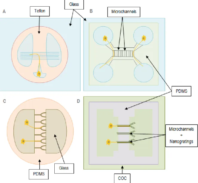
Ross Harrison demonstrated in 1910 [45] that neurons can be cultured outside the body. From Harrison’s first culture in the hanging drop (i.e. culture cells in suspended liquid drops) to the present, developments in culture methodologies have emerged and advanced neuroscience research in vitro. Culture flasks were firstly developed to culture and analyze neurons, but in the last few decades, patterned substrates and microfluidic devices have been applied on neuronal culturing [45]. As reviewed by Gross et al. [82], many platforms have been designed around the unique anatomy of neural cells. As neural cell bodies and axons have distinct properties and functions, novel designs allowed the isolation and analysis of individual neural cells and single neurites.
Although pipettes remain the standard method for electrical isolation of different compartments (i.e., patch clamping), microfluidic systems have contributed with feasible compartmentalization methods [78]. The Campenot method used a three-compartment Teflon chamber to isolate axons from the