UNIVERSIDADE DA BEIRA INTERIOR
Engenharia
Numerical Analysis of a Single Droplet Impinging
upon Liquid Films using the VOF Method
Daniel de Almeida Vasconcelos Rodrigues
Dissertação para obtenção do Grau de Mestre em
Engenharia Aeronáutica
(ciclo de estudos integrado)
Orientador: Prof. Doutor André Resende Rodrigues da Silva
In memory of my father, Luís Rodrigues
Acknowledgements
First, i would like to express my sincere gratitude to my supervisor, Professor André Resende Rodrigues da Silva, for the valuable support and guidance in writing this dissertation. His mo-tivation and enthusiasm, coupled with immense knowledge, encouraged me to strive towards improving my work.
I am thankful for the opportunity to be affiliated with AeroG - Aeronautics and Astronautics Research Center, directed by Professor Jorge Manuel Martins Barata. This research and devel-opment unit provided the resources required for this dissertation.
I am grateful to all my colleagues at AeroG with whom I had the pleasure to devote countless hours to both scientific research and life in general. I would especially like to thank my fellow colleague, PhD student Daniela Ribeiro, for the patience and persistence it took to support me during the ups and downs of researching and writing this dissertation.
I would like to thank my friends who, over these years, shared and experienced memorable moments with me. Not only were we able to support each other but also enriching our academic life and discussing things other than research.
Lastly, I would like to thank my family for their unconditional support and dedication through-out this journey. I personally thank my mother and brother, whose love and guidance were fundamental in my life.
Resumo
Nas últimas décadas, o desenvolvimento de alternativas aos combustíveis fósseis tem-se tornado gradualmente mais relevante. Os biocombustíveis, em particular, atraem interesse, não apenas como uma alternativa ao elevado custo dos combustíveis fósseis, mas também como solução para vários desafios que o mundo moderno enfrenta atualmente. Estes desafios incluem preo-cupações com a segurança energética, desenvolvimento económico, a necessidade de mitigar a mudança climática e redução das emissões de gases de efeito de estufa.
O principal objetivo desta dissertação é simular numericamente o impacto vertical de uma gota sobre uma superfície líquida com iguais propriedades e envolvida por ar. Foram considerados quatro fluidos: água, 100% Jet A-1 e 75%/25% e 50%/50% de Jet A-1 e NEXBTL, respectivamente. Particularmente, os modelos multifásicos são fenómenos complicados na natureza devido à di-ficuldade em prever, com precisão, a interface entre as diferentes fases.
O modelo numérico consiste em resolver as equações de Navier-Stokes a partir do método ex-plícito do Volume de Fluido (do inglês, Volume of Fluid) para um modelo bidimensional (2D) axissimétrico. Esta análise considera vários parâmetros e métodos para caracterizar a dinâmica do impacto de gotas. As propriedades físicas dos fluidos, a gravidade e os ângulos de contacto são utilizados para clarificar este modelo. Em termos de abordagem dos métodos de solução, o Método de Etapa Fracionária (em inglês, Fractional Step Method) resolve numericamente as equações incompressíveis de Navier-Stokes, o esquema de Reconstrução Geométrica (em inglês,
Geometric Reconstruction) delimita a interface entre o líquido e a gás e o modelo de Força de
Superfície Contínua (em inglês, Continuum Surface Force) inclui os efeitos da tensão superfi-cial. Os resultados numéricos são validados qualitativa e quantitativamente com os resultados experimentais disponíveis.
Seis cenários diferentes foram simulados numericamente: Prompt Splash, Crown Splash,
Spread-ing, JettSpread-ing, Fingering e Bubbling. Os primeiros quatro fenómenos referidos estão de acordo
com os resultados experimentais em termos do impacto inicial e da expansão da coroa. O fenó-meno de fingering apresentou vários problemas relativos ao desenvolvimento da coroa devido à natureza tridimensional (3D) das instabilidades formadas nos limites externos da coroa. O fenómeno de bubbling não foi possível de recriar numericamente. É necessário compreender a dinâmica deste fenómeno e como, atualmente, a pesquisa atual é escassa, estudos devem ser feitos para entender as peculiaridades da formação deste tipo de cúpulas. Também foi visuali-zado a ocorrência de prompt splash para as fases iniciais do crown splash e do bubbling, que não correspondiam aos resultados experimentais. Há várias razões que justificam essa discrepância, como a dificuldade de capturar as gotas extremamente pequenas provenientes da atomização secundária ou os métodos de solução forçarem o splash inicial em alguns casos. Em termos de análises futuras, simulações 3D são necessárias para averiguar o número, tamanho e velocidade das gotas provenientes da atomização secundária. O fenómeno de bubbling também requer um estudo mais exaustivo no comportamento da dinâmica do impacto das gotas.
Palavras-chave
Abstract
Over the last few decades, developing alternatives to fossil fuels has become increasingly im-portant. Biofuels, in particular, have attracted interest not only as an alternative to expensive fossil fuels but also by providing a solution to several challenges that the modern world currently faces, which include worries regarding energy security, economic development, the need to mitigate climate change and achieving lower greenhouse gas emissions.
The major objective of this dissertation is numerically simulating the vertical impact of a single droplet upon a liquid surface with the same liquid properties and surrounded by air. Four fluids were taken into account: water, 100% Jet A-1 and 75%/25% and 50%/50% of Jet A-1 and NEXBTL, respectively. Particularly, multiphase flows are complicated phenomena in nature due to the difficulty in accurately predicting the interface between the phases.
The numerical model consists of solving the Navier-Stokes equations by means of the explicit Volume of Fluid (VOF) method for a 2D axisymmetric assumption. This analysis considers sev-eral parameters and models that define this phenomenon. The physical properties of the liquid and gas, which are density and viscosity, surface tension, gravity and the contact angles of the different fluids represent our physical model. For the solution approach, the Fractional Step Method (FSM) numerically solves the Navier-Stokes incompressible equations, the Geometric Reconstruction scheme tracks the interface between the liquid and the gas phase and the Con-tinuum Surface Force (CSF) model includes the effects of surface tension. The numerical results are validated both qualitatively and quantitatively with available experimental results.
Six different outcomes were numerically simulated: Prompt Splash, Crown Splash, Spreading, Jetting, Fingering and Bubbling. The numerical results for the initial four outcomes are in good agreement with the experimental results in terms of the initial impact and crown expansion. The fingering phenomenon displayed several issues concerning crown development due to the 3D nature of the instabilities formed at the crown rim. The bubbling phenomenon was not possible to numerically recreate. Information regarding the dynamics of this phenomenon is scarce and more research is required to understand the peculiarities of dome formation. It was also visualized prompt splash for the crown splash and bubbling initial stages, which did not correspond to the experimental results. There are several reasons that justify this discrepancy, such as the difficulty in capturing very tiny ejected droplets or the solution approach forcing prompt splash on some of the cases. Overall, 3D simulations are required for future analysis to accurately predict secondary atomization. Work toward the bubbling phenomenon must also be considered.
Keywords
Index
Dedicatória . . . iii
Acknowledgements . . . v
Resumo . . . vii
Abstract . . . ix
List of Figures . . . xiii
List of Tables . . . xv
Nomenclature . . . xvii
Acronyms and Abbreviations . . . xix
1 Introduction 1 1.1 Motivation . . . 1 1.2 Objectives . . . 2 1.3 Overview . . . 2 2 Literature Review 3 2.1 Introduction . . . 3 2.2 Non-dimensional Parameters . . . 4
2.3 Classification of impact targets . . . 5
2.3.1 Dry Surfaces . . . 6 2.3.1.1 Stick . . . 7 2.3.1.2 Deposition/Spread . . . 8 2.3.1.3 Prompt splash . . . 8 2.3.1.4 Corona splash . . . 8 2.3.1.5 Receding breakup . . . 9
2.3.1.6 Complete and Partial rebound . . . 9
2.3.1.7 Fingering and Finger Breakup . . . 9
2.3.2 Wetted Surfaces . . . 10
2.4 Splashing phenomenon . . . 14
2.5 Numerical Methods Applied to Single Droplet Impact . . . 17
3 Numerical Setup 19 3.1 Volume of Fluid (VOF) Model . . . 19
3.1.1 Introduction . . . 19
3.1.2 Governing Equations . . . 20
3.1.3 Surface Tension and Wall Adhesion . . . 22
3.2 Flow Configuration . . . 24
3.2.1 Contact Angles . . . 25
3.3 Numerical Modelling . . . 27
3.3.1 Geometry and Meshing . . . 27
3.3.2 General Settings . . . 28
3.3.3 Adopted Models . . . 29
3.3.4 Boundary Conditions . . . 30
3.3.5 Solution Approach . . . 31
3.3.6 Initialization . . . 33
4 Results and Discussion 37 4.1 Visualization . . . 37 4.1.1 Prompt Splash . . . 37 4.1.2 Crown Splash . . . 39 4.1.3 Spreading . . . 41 4.1.4 Jetting . . . 42 4.1.5 Fingering . . . 44 4.1.6 Bubbling . . . 45 4.2 Quantitative Analysis . . . 47 4.3 Summary . . . 49
5 Conclusions and Future Work 51 5.1 Conclusions . . . 51
5.2 Future Work . . . 52
References 55
List of Figures
2.1 Outcome of single droplets impacting onto non-heated dry surfaces based on its
impact energy . . . 6
2.2 Outcome of single droplets impacting onto non-heated dry surfaces based on its time scale . . . 7
2.3 Stick regime illustration . . . 7
2.4 Deposition regime illustration . . . 8
2.5 Prompt splash regime . . . 8
2.6 Corona splash regime . . . 8
2.7 Receding breakup regime . . . 9
2.8 Partial rebound regime . . . 9
2.9 Complete rebound regime . . . 9
2.10 Fingering and Finger Breakup regime . . . 10
2.11 Visual representation of a droplet approaching the liquid film . . . 11
2.12 Visual representation of the ejecta sheet . . . 12
2.13 Visual representation of the crown evolution . . . 12
2.14 Crown splash representation: (a) Sketch of splashing mechanism: 1 - residual top of impacting drop; 2 - wall; 3 - section of crown-like sheet propagating outwards; 4 - cross-section of free rim; 5 - secondary droplets formed from cusps of free rim; 6 liquid layer on wall. (b) Free rim and secondary droplets magnified: 1 -crown-like sheet; 2 - free rim at its top edge; 3 - cusp; 4 - thin jet emerging at cusp; 5 - secondary droplets formed on breakup of jet. . . 13
2.15 The effect of the density ratio on the crown shape: (a) ρ∗ = 815, (b) ρ∗ = 400, (c) ρ∗= 200, (d) ρ∗= 100, (e) ρ∗ = 50, and (f ) ρ∗= 25 . . . 16
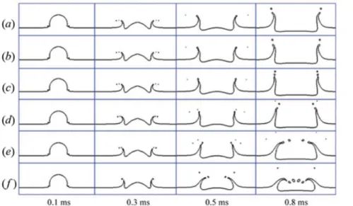
2.16 The effect of the viscosity ratio on the crown shape: (a) µ∗ = 56, (b) µ∗= 5, (c) µ∗= 1, (d) µ∗= 0.5, (e) µ∗= 0.05, and (f ) µ∗= 0.01 . . . 16
3.1 Possible contact angles of a drop impacting onto an ideal surface: a) complete wetting; b) partial wetting; c) partial non-wetting; d) complete non-wetting . . . 23
3.2 Stationary H2O droplet t = 200ms after impact. . . . 26
3.3 Droplet after the implementation of the algorithm. . . 27
3.4 Initial representation of the geometry and mesh of the physical model. . . 28
3.5 Boundary conditions of the physical model. . . 30
3.6 Visual representation of the droplet and the liquid film for t = 0ms. . . . 34
3.7 Mesh refinement study of the numerical model for the inner diameter of the crown, non-dimensionalized by the droplet diameter, as a function of the mesh size. . . 35
3.8 Mesh refinement study of the numerical model for the inner diameter of the crown, non-dimensionalized by the droplet diameter, as a function of the dimen-sionless time. . . 36
4.1 Visualization of the prompt splash phenomenon for the 50% JF/50% HVO mixture (D0 = 3.1mm, U0 = 4.1m/s, h∗ = 0.1): (a) Experimental Results; (b) Numerical analysis. . . 38
4.2 Visualization of the crown splash phenomenon for H2O (D0 = 3.2mm, U0 = 4.1m/s, h∗= 0.27): (a) Experimental Results; (b) Numerical analysis. . . . 40 4.3 Visualization of the spreading phenomenon for the 75% JF/25% HVO mixture (D0=
2.8mm, U0= 1.8m/s, h∗= 1): (a) Experimental Results; (b) Numerical analysis. . 42 4.4 Visualization of the jetting phenomenon for the 100% JF (D0 = 3.0mm, U0 =
1.8m/s, h∗= 1): (a) Experimental Results; (b) Numerical analysis. . . 43 4.5 Visualization of the fingering phenomenon for the 75% JF/25% HVO mixture (D0=
2.5mm, U0= 1.8m/s, h∗= 0.1): (a) Experimental Results; (b) Numerical analysis. 45 4.6 Visualization of the bubbling phenomenon for the 75% JF/25% HVO mixture (D0=
3.1mm, U0= 4.1m/s, h∗= 0.5): (a) Experimental Results; (b) Numerical analysis. 47 4.7 Development of the outer diameter of the crown as a function of the crown height,
both non-dimensionalized by the droplet diameter, for t = 6ms. . . . 48 4.8 Quantitative analysis of the outer diameter of the crown as a function of time,
List of Tables
2.1 Various impact regimes for impact on a wetted surface . . . 10 3.1 Physical properties of density, dynamic viscosity and surface tension of the
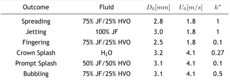
dif-ferent fluids . . . 24 3.2 Possible outcomes and respective droplet diameter, impact velocity and
dimen-sionless thickness. . . 24 3.3 Possible outcomes and respective Reynolds, Weber, Ohnesorge and Laplace Numbers 25 3.4 Static contact angles onto a perspex surface for the different fluids . . . 27
Nomenclature
Bo Bond Number [−]
C Courant Number [−]
Cmax Maximum value of the Courant Number [−]
Ca Capillary Number [−]
D0 Droplet Diameter [mm]
Din Crown Inner Diameter [mm]
Dout Crown Outer Diameter [mm]
F External Body Forces [N ]
FCSF Surface Tension Force [N ]
F r Froude Number [−]
g Gravitational Acceleration Constant [m/s2]
h Film Thickness [mm]
h1, h2, h3 Impact Heights: h1= 0.175; h2= 0.5; h3= 1 [m]
h∗ Relative Film Thickness [−]
H Crown Height [mm]
H∗ Non-dimensional Crown Height [−]
H2 Grid Height [mm]
I Unit Tensor [−]
La Laplace Number [−]
La Lenght Scale of Wall Roughness [mm]
Lnd Non-Dimensional Lenght Scale of Wall Roughness [−]
˙
m Mass Flow Rate [kg/s]
M Mach Number [−]
n Normal Surface at the Curvature [−]
ˆ
n Normal Unit [−]
ˆ
nw Normal Unit Vector to the Wall [−]
Oh Ohnesorge Number [−]
p Static Pressure [kg/(m.s2)]
pgauge Static Gauge Pressure [kg/(m.s2)]
Re Reynolds Number [−]
Ra Arithmetical Mean Value of Wall Roughness [mm]
Rnd Non-Dimensional Arithmetical Mean Value of Wall Roughness [−]
Sm Source Term [−]
Sαq Source Term [−]
t Time [ms]
∆t Time Step [ms]
ˆ
tw Tangential Unit Vector to the Wall [−]
U Velocity [m/s]
U0 Droplet Impact Velocity [m/s]
Uxi Velocity in the xi direction [m/s]
V 1 Grid Radial Distance [mm]
∆xi Length Interval in the xidirection [mm]
Greek symbols
α Volume Fraction [−]
κ Interface Curvature [−]
µ Dynamic Viscosity [mP a.s]
µ∗ Dynamic Viscosity Ratio [−]
ρ Density [kg/m3] ρ∗ Density Ratio [−] σ Surface Tension [mN/m] τ Non-dimensional Time [−] ¯ τ Stress Tensor [−]
θw Static Contact Angle [◦]
Subscripts
0 Refers to the Droplet
g Gas phase
l Liquid Phase
p pPhase
q qPhase
Acronyms and Abbreviations
2D Two-Dimensional 3D Three-Dimensional ANSYS Analysis of Systems BIM Boundary Integral Method CFL Courant-Friedrichs-Lewy
CICSAM Compressive Interface Capturing Scheme for Arbitrary Meshes CLSVOF Coupled Level Set and Volume of Fluid Method
CPU Central Processing Unit CSF Continuum Surface Force CSS Continuum Surface Stress DNS Direct Numerical Simulation FSM Fractional Step Method
HRIC High Resolution Interface Capturing HVO Hydrotreated Vegetable Oil
ITA Iterative Time-Advancement
JF Jet Fuel
LBM Lattice-Boltzmann Method LSM Level Set Methods
MAC Marker and Cell MATLAB Matrix Algorithm
MPS Moving Particle Semi-Implicit
MUSCL Monotonic Upwind Scheme for Conservation Laws NEXBTL Neste Renewable Diesel
NITA Non-Iterative Time-Advancement
PISO Pressure-Implicit with Splitting of Operations PRESTO! Pressure Staggering Option
QUICK Quadratic Upstream Interpolation for Convective Kinematics SIMPLE Semi-Implicit Method for Pressure-Linked Equations
SPH Smooth Particle Hydrodynamics UBI Universidade da Beira Interior VOF Volume of Fluid
Chapter 1
Introduction
This dissertation focuses on numerically simulating the droplet impact phenomenon onto liquid films. The current chapter presents an initial introduction to this topic.
The first section describes the motivation in biofuels and numerical analysis, the second section enumerates the different objectives for the current work and the third and final section displays the structure of this dissertation.
1.1
Motivation
Over the last few decades, developing alternatives to fossil fuels has become increasingly im-portant. Biofuels, in particular, have attracted interest not only as an alternative to expensive fossil fuels but also by providing a solution to several challenges that the modern world currently faces, which include worries regarding energy security, economic development, the need to mitigate climate change and achieving lower greenhouse gas emissions [1].
The issue regarding energy security relies on the fact that there are few alternatives to fossil fuels when it comes to transportation and fuelling internal combustion engines. Introducing biofuels allows to diversify some of the reliance on fossil energy sources and to manufacture home-produced fuels. Increasing the investment in biofuels also promotes economic develop-ment, including the creation of new jobs and sources of income for farmers. This would mostly benefit developing countries, in which a large proportion of the population is employed in agri-culture, in the demand for world energy. With the appropriate method of production, biofuels will produce significantly lower greenhouse gas emissions than those emitted by the current fossil fuels. Although most of the current aircraft and heavy vehicles have no carbon-neutral alternative options, the current civil aviation legislation allows for fuel mixtures up to 50% of biofuel, which implies a minimum percentage of 50% of jet fuel.
This dissertation is focused on numerically simulating droplet impact phenomenon onto liquid films. It appears in a wide variety of engineering areas such as ink-jet printers, internal combus-tion engines, spray cooling, among others. The research of this study has been motivated by the need for a better predictive capability in these industries. Ribeiro [2] experimentally studied this phenomenon using jet fuel and biofuel mixtures and this work will provide a comparison between the experimental and the numerical results.
Numerical analysis relies on solving equations of a certain mathematical model to try and repre-sent a physical phenomenon. Specifically, multiphase flows couple the Navier-stokes equations with an interface-tracking method in order to represent how different phases respond when coexisting in the same environment. These flows are complicated to represent and, since the complex interactions between the droplet and the liquid film are still far from being fully under-stood, the current methods might not be accurate enough to predict the different interactions between the phases. Therefore, since the use of numerical simulations is becoming progressively
important with the increase in computing power available, improving efficiency and reliability on our simulations is of interest.
1.2
Objectives
A proper understanding of multiphase models and droplet impact dynamics is still lacking, both experimentally and numerically. The main objective of this dissertation is accurately predict-ing the different outcomes visualized by Ribeiro [2] uspredict-ing the Volume of Fluid (VOF) method. Accomplishing it requires the following:
• Numerical simulation of the six different outcomes visualized by Ribeiro [2];
• Validation and verification of the mathematical model and numerical approach, respec-tively;
• Comparison between the numerical and the experimental results in terms of crown devel-opment, splashing and outcome.
1.3
Overview
This dissertation is organized as follows: Introduction, Literature Review, Numerical Setup, Results and Discussion and Conclusions and Future Work.
The first and current chapter includes the motivation presented for this dissertation, concerning biofuels and numerical methods, the objectives provide an accurate description of the specific actions taken to reach a certain goal and the overview refers to the thesis organization on the different chapters and subjects.
The second chapter is dedicated to the review of the bibliography regarding droplet impact dynamics for both experimental and numerical fields. This includes non-dimensional numbers, classification of impact targets, such as dry and wetted surfaces, droplet dynamics referring to the splashing phenomenon and crown development and, lastly, a variety of numerical methods capable of predicting interactions between different phases.
The third chapter describes the numerical model. Initially, the Volume of Fluid (VOF) model is meticulously explained in terms of its applications, governing equations and specific models. Afterwards, the numerical approach to the physical model is presented, as the geometry, mesh-ing, boundary conditions, adopted models, solution approach and initialization are detailed. A grid independence study is performed to guarantee validation of the numerical results, as well as a comparison between experimental and numerical data.
The fourth chapter exhibits the numerical analysis of the different outcomes and the comparison with the experimental results in terms of splashing, crown evolution and overall development of the phenomena. The final chapter presents the conclusions and possible future work for this dissertation.
Chapter 2
Literature Review
The current chapter unveils the overall phenomenon of the single droplet impact. The first section presents the main factors that influence the droplet impact dynamics on liquid films and the dimensionless parameters that govern this kind of impact. This section is an introduction to the mechanisms of drop impact.
The second section is dedicated to the impact target classification, which includes dry and wetted surfaces. Even though the splash morphology on a dry surface may be similar to that on a liquid film, the mechanisms that lie underneath for the two surface targets are fundamentally different. Therefore, distinct types of impact are presented for these surfaces and a deeper explanation of how the different parameters affect crown development in terms of thickness, height, diameter, etc, is presented.
Recognizing that the splashing and the non-splashing phenomena involve different processes and exhibits such different patterns is the first step in understanding how the droplet behaves when impinging on liquid films. Therefore, the third section fully describes droplet splashing, which results from high energy impact. Every aspect that might determine if splashing occurs or not, such as viscosity, surface tension, etc, is presented. The influence of these parameters on the formation of secondary droplets in terms of size, number and stage are also reviewed.
The fourth and last section of this chapter is dedicated to numerical methods. Different numer-ical models that have been adopted to simulate droplet impact upon liquid films are reviewed, such as grid-based methods, Lagrangian particle methods, among others. Several differences are stated between them, as the main purpose of this section is introducing the following chap-ter that is fully dedicated to the VOF method and the numerical analysis of impacting droplets.
2.1
Introduction
The phenomenon regarding impact of single drops onto a liquid film is rather interesting and complex. It has a great number of applications on different fields such as internal combustion engines, spray cooling, pesticide spraying of crops [3], soil and stone erosion [4], atomization of dangerous liquids, dispersal of spores and micro-organisms and coating process, among oth-ers. This phenomenon is mostly seen in nature when the raindrops impinge on already wetted surfaces on the ground.
Despite the different applications, scientific research on drop impact is mainly driven by its applications in industrial technology and equipment due to its favourable heat and mass trans-fer potential and, although the researchers have been studying this content for decades, the complex interactions between the droplet and the liquid film are still far from being fully un-derstood.
phenomenon regarding impact target classification, drop impact mechanisms, the main factors that influence the drop impact dynamics, non-dimensional parameters, etc.
2.2
Non-dimensional Parameters
According to Yarin [5] and Motzkus [6], the main parameters that define the droplet impact on liquid films are divided into three categories: the liquid drop, the liquid film and the sur-rounding air. The different combinations of these properties define a variety of dimensionless parameters that govern the impact dynamics on liquid films. These parameters involve the Reynolds number, the Weber number, the Ohnesorge number, the Laplace number, the Froude number, the Capillary number, among others. A thorough explanation of the non-dimensional parameters is presented in order to comprehend the mechanisms behind droplet impact. As reviewed by Yarin [5] and Liang [7], there are several dimensionless parameters involving these phenomena. Some of the most important dimensionless numbers for this kind of impact are the Reynolds number, Re, the Weber number, W e, and the Ohnesorge number, Oh. The Reynolds number is defined as the ratio between the inertial and viscous forces, the Weber number relates the inertial to the surface tension forces and the Ohnesorge number is represented as the ratio between the viscous forces and the inertial and the surface tension forces, as seen in equations 2.1, 2.2 and 2.3, respectively: Re = ρlD0U0 µl (2.1) W e = ρlD0U 2 0 σ (2.2) Oh = √ µl ρlσD0 = √ W e Re (2.3)
where ρ is the density, D0 is the droplet diameter, U0 is the droplet impact velocity, µ is the dynamic viscosity, σ is the surface tension and the subscript l refers to the liquid phase. The Ohnesorge number can also be represented as the ratio between the square root of the Weber number and the Reynolds number.
Following this, there are other three non-dimensional parameters that, despite not being rel-evant to this dissertation, are worth mentioning. The Froude number, F r, is defined as the ratio between the inertial and the gravitational forces, the Capillary number, Ca, is described as the ratio between the viscous and the surface tension forces and the Bond number, Bo, rep-resents the ratio between the gravitational and the surface tension forces. Respectively, the parameters are represented by the equations 2.4, 2.5 and 2.6.
F r = √U0 gD0 (2.4) Ca = µU0 σ = W e Re (2.5)
Bo = ρlgD 2 0 σ = W e F r (2.6)
where g is the gravitational acceleration constant. Since gravity effects can be neglected for
F r ≥ 10 [5, 8], then gravity effects are not important when considering the phenomenon of
droplet impact.
The Laplace number, La, is described by the ratio between the surface tension forces and the momentum-transport (especially dissipation) inside a fluid and it is defined by the equation 2.7. It can also be expressed through non-dimensional parameters.
La = ρlσD0 µ2 l =Re 2 W e (2.7)
According to Liang [9], the ratios of liquid-gas density and viscosity are also important to char-acterize the drop impact on a liquid film. They are represented by equation 2.8 and 2.9, re-spectively: ρ∗= ρl ρg (2.8) µ∗= µl µg (2.9)
where the subscript g refers to the gas phase. The last non-dimensional parameter referred to in this section is the non-dimensional time. It is described as the ratio between the product of the impact velocity and time, t, and the droplet diameter. This non-dimensional parame-ter characparame-terizes the different stages of the droplet impact phenomenon and is expressed by equation 2.10.
τ = U0t D0
(2.10)
Although the different non-dimensional parameters have been presented and thoroughly de-scribed, an explanation of how the droplet reacts regarding the impact target is now needed. As mentioned before, the mechanisms that define each type of impact targets are fundamentally different and need to be reviewed.
2.3
Classification of impact targets
In general, impact targets can be classified into dry and wetted surfaces. Over this section, the different mechanisms between dry solid surfaces and liquid films are distinguished. Droplet impact onto liquid films with a dimensionless thickness greater than one will not be considered here, as the condition of droplet impact onto films with dimensionless thickness, smaller than unity, is often satisfied in the engine environment [10]. The dimensionless thickness, as one of the most important non-dimensional numbers for droplet impact onto liquid films, is profoundly explained over subsection 2.3.2. Despite the work of this dissertation being focused on the
numerical simulation of droplet impact on wetted surfaces, a deep understanding of dry solid surfaces and liquid films is necessary to comprehend the differences behind this two impact surfaces.
2.3.1
Dry Surfaces
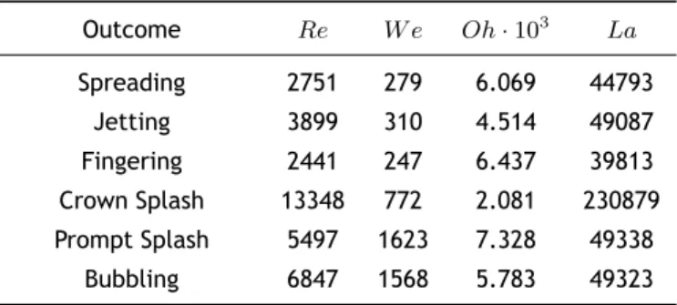
The phenomena which occur when a single droplet impacts on a non-heated dry surface exhibits different mechanisms that depend on many factors, such as the interface and the impact con-ditions. Figures 2.1 and 2.2 display several outcomes, differently enumerated, regarding this kind of impact. Those outcomes are basically identified as stick (i), spread (ii) and splash (iii). During spread, it might occur fingering (iv) and, at later stages, the droplet may rebound (v) from the surface. Rioboo et al. [11] added the occurrence of fingering (iv), already mentioned, and replaced the term ”splash” with ”disintegration”. Four disintegration mechanisms were differentiated, which involve prompt splash a), corona splash b), receding breakup (iii-c) and partial rebound (iii-d). More recently, Moita and Moreira [12] added a new mechanism, denominated the finger breakup (iii-e). Later on, these different phenomena will be thoroughly interpreted.
According to Bai and Gosman [13] and Rioboo et al. [11], we can distinguish these phenomena by their impact energy and time scale, respectively, as displayed on figures 2.1 and 2.2.
Figure 2.1: Outcome of single droplets impacting onto non-heated dry surfaces based on its impact energy by Bai and Gosman [13].
1
Figure 2.2: Outcome of single droplets impacting onto non-heated dry surfaces based on its time scale by Rioboo et al. [11].
At low impact energy values, the droplet sticks to the wall but, as the impact energy increases, a lamella forms which spreads and recoils until all the energy is dissipated. At certain impact velocities, the rim of the lamella may start to destabilize when the spreading phase begins, which may lead to the formation of regular structures called fingers, which grow ahead of the contact line and further breakup during the last stages of spreading, e.g. Yoon and Desjardin [14]. These structures were studied by several authors [15, 16, 17]. However, Yarin [5] reviewed with detail the fundamentals of the fingering mechanism.
In order to better comprehend dry surfaces, since the phenomena also occur with certain simi-larity on wetted surfaces, a deeper explanation is presented.
2.3.1.1 Stick
This outcome occurs when the impact energy is very low. Once the droplet impacts with the surface, it keeps its spherical shape. This kind of outcome is only seen for impacts on dry surfaces and the droplet tends to maintain its spherical shape, also due to the surface roughness.
2.3.1.2 Deposition/Spread
According to Rioboo et al. [11], deposition is said to occur when the droplet spreads on the surface at impact and remains attached at the surface during the entire impact process without the formation of secondary droplets. It also occurs for low impact energy values. Bai and Gosman [13] defined the same phenomenon as spread. However, Coppola et al. [19] established some differences between these two phenomena. Despite both representing droplets merging with the liquid surface without emitting any kind of secondary atomization, deposition occurs at lower impact velocities where the impact fails to generate capillary waves. These waves are created when thin liquid sheets emitted subsequent to impact grow into a lamella that propagates radially, thus creating capillary waves. In this dissertation, deposition and spreading are defined as the same phenomenon, following the same terminology as Ribeiro [2].
Figure 2.4: Deposition regime illustration by Rioboo et al. [11].
2.3.1.3 Prompt splash
The prompt splash is promoted by a higher impact energy on rough surfaces. Once the droplet impacts the surface, it disintegrates, resulting in tiny droplets detaching from the periphery of the liquid lamella generated by the spreading drop. At the end of this process, the droplet spreads on the wall. This kind of splash occurs at the beginning of the spreading phase.
Figure 2.5: Prompt splash regime by Rioboo et al. [11].
2.3.1.4 Corona splash
The corona splash, also called crown or delayed splash, occurs when the liquid lamella detaches from the wall, forming droplets around the rim of a corona. This phenomenon occurs at a later stage of the impact process and it is also characteristic on liquid film impact.
2.3.1.5 Receding breakup
As the liquid retracts from its maximum spreading radius, due to the fact that the contact angle decreases during retraction, if the limiting value of zero is reached, it may cause some drops to be left behind by the receding lamella.
Figure 2.7: Receding breakup regime by Rioboo et al. [11].
2.3.1.6 Complete and Partial rebound
Only occurs when a drop recedes after impact, e.g., if a receding phase is observed. According to Ribeiro [2], this phenomenon can also be called jetting and, since the terminology should match between these dissertations, this outcome is defined as jetting in this dissertation as well. As the drop recedes to the impact location, the kinetic energy of the impinging drop causes the liquid to extend vertically through the centre, forming a vertical liquid column called ”jet”. If, due to capillary instability, the droplet can stay partly at the surface and launch one or more droplets at its top, it is denominated partial rebound. However, if it detaches from the surface as an intact drop, it is denominated as complete rebound.
Figure 2.8: Partial rebound regime by Rioboo et al. [11].
Figure 2.9: Complete rebound regime by Rioboo et al. [11].
2.3.1.7 Fingering and Finger Breakup
According to Marmanis and Thoroddsen [16] and Yarin [5], when, during the drop impact, there are certain disturbances that affect the associated patterns of the impact, mostly azimuthal disturbances, their growth results in fingering at the rim of a spreading drop on a dry wall. This phenomenon was also reported by Ribeiro [2] in liquid films with a dimensionless thickness of 0.1. If, however, the developed fingers experience further breakup, likely due to capillary instability, secondary droplets are ejected. This phenomenon is defined as Finger Breakup.
Figure 2.10 displays the fingering and the finger breakup regime and, despite this particular case occurring on a wet surface, this figure was preferred for the visualization of the phenomenon.
Figure 2.10: Fingering and Finger Breakup regime. Adapted from Deegan et al. [8].
2.3.2
Wetted Surfaces
The impact of single drops on thin liquid films was studied to understand the mechanism of secondary atomization of sprays colliding on a wetted, cold, solid surface. Before starting to address these impact mechanisms, it is important to determine how liquid films are defined. Tropea and Marengo [20] identified and divided liquid films into four different categories.
Table 2.1: Various impact regimes for impact on a wetted surface. Adapted from Tropea and Marengo [20].
Regime Range Impact characteristics
Thin liquid film Lnd< h∗< 3R0.16nd Impact depends on surface features
Medium liquid film
3R0.16
nd < h∗< 1.5 Impact is weakly dependent on surface features
Shallow pool 1.5 < h∗< 4 Impact depends on film thickness but is independent of surface characteristics
Deep pool h∗> 4 Impact is independent of film thickness
In order to understand the different ranges for the different regimes, there are some equations that need to be introduced.
Equation 2.11 describes one of the most important non-dimensional numbers used to define liquid films, which is dimensionless thickness. It is described as the ratio between film thick-ness and drop diameter and different values of this number will result in different outcomes. Equations 2.12 and 2.13 refer to the arithmetical mean value of wall roughness, Ra, and length
scale of the wall roughness, La, also non-dimensionalized by the drop diameter, respectively.
h∗= h/D0 (2.11)
Rnd= Ra/D0 (2.12)
Before introducing the different stages of drop impact on liquid films, we have to separate and present the differences between splash and deposition. In this dissertation, and to follow the terminology adopted by Ribeiro [2], the term splash will be used to indicate the formation of secondary droplets after the impact of the impinging drop and the term deposition will indicate an impact without the production of secondary droplets.
Despite most of the phenomena found on dry surface impact being similar to those found on wetted surface impact, as well as most of them occurring on both conditions, there are particular differences that must be mentioned.
Another possible outcome, barely mentioned in the literature, is bubbling. Reported by Mack-lin and Metaxas [21], this phenomenon consists on the formation of a dome or bubble after a crown splash event. The bubbling episode is essentially defined by liquid films with a higher relative thickness, such as deep pools. However, Ribeiro [2] reported this same phenomenon for a dimensionless thickness of h∗= 0.5.
Since droplet impact on wetted surfaces is a rather complex phenomenon and involves a massive number of variables, a profound definition of the different stages of this kind of impact is required.
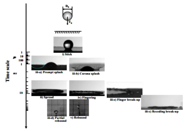
There are five different stages regarding droplet impact on liquid films. Figure 2.11 represents the initial phase of this phenomenon. The droplet starts its vertical descent from a predefined height, gaining velocity as it approaches the liquid film. We can observe different parameters from the droplet, the gas and the liquid film, as mentioned in section 2.2.
Figure 2.11: Visual representation of a droplet approaching the liquid film. Adapted from Liang [7].
Figure 2.12 represents the formation of the ejecta sheet. Once the droplet impacts the liquid film, a thin axisymmetric sheet arises during the earliest stages of the impact. This particular sheet emerges through the neck region between the droplet and the bottom layer where the two liquid masses connect. According to Thoroddsen [22], the ejecta sheet is originated from the underlying liquid film, not the liquid droplet. Josserand and Zaleski [23] concluded that viscosity plays a major role in the neck region, defining the width of the ejecta sheet that will later develop into a crown. Surface tension serves to either allow or prevent the formation
of the ejecta sheet. If the existing conditions are not favourable, the ejecta sheet will not develop. However, if it develops due to favourable conditions, this sheet becomes the leading edge of the crown sheet and it starts to bend down, colliding with the liquid film and breaking up immediately, causing prompt splash. This occurrence may cause irregularities in the crown sheet and rim. The remaining initial ejecta sheet is pulled up by the developing crown, as observed in figure 2.13.
Figure 2.12: Visual representation of the ejecta sheet. Adapted from Liang [7].
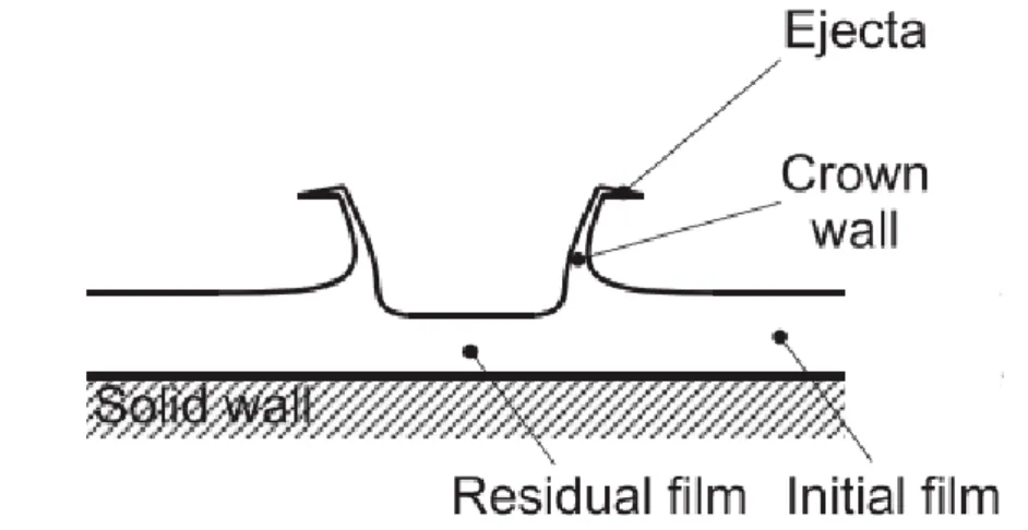
Figure 2.13 displays the transition from the initial impact, where the ejecta sheet may be formed, into the initial crown formation. The ejecta sheet keeps its horizontal shape while the crown wall height increases due to the crown development. The liquid film outside of the crown wall, which we denominate as the initial film, remains its initial thickness. However, the liquid film located inside the crown wall (the impact region between the droplet and the film) has its thickness reduced, due to the fact that part of the crown wall liquid derives from the liquid film underneath.
Figure 2.13: Visual representation of the crown evolution by Liang [7].
Once the crown fully develops, there are two possible outcomes. The first outcome is the crown formation without splashing, which means there are no secondary droplets ejected from the rim. The second outcome is the crown formation with splashing, which is represented by figure 2.14. This outcome is characterized by the detachment of the liquid lamella from the crown wall, forming droplets around the rim of a corona, as described in section 2.3.1.4.
(a) (b)
Figure 2.14: Crown splash representation by Yarin and Weiss [24]: (a) Sketch of splashing mechanism: 1 residual top of impacting drop; 2 wall; 3 section of crownlike sheet propagating outwards; 4 -cross-section of free rim; 5 - secondary droplets formed from cusps of free rim; 6 - liquid layer on wall.
(b) Free rim and secondary droplets magnified: 1 crownlike sheet; 2 free rim at its top edge; 3 -cusp; 4 - thin jet emerging at -cusp; 5 - secondary droplets formed on breakup of jet.
There are different aspects that characterize the crown development itself. There is the crown wall, the free rim, the liquid film inside and outside of the crown, as well as the formation of secondary droplets from the free rim if the conditions are favourable. The occurrence of splashing will be detailed thoroughly in the following section.
The crown evolution may depend on several factors, such as liquid viscosity, dimensionless thick-ness, etc. These factors may alter the way how the crown evolves, as in faster development, smaller height or even thinner crown walls. The crown formation can be divided into four main geometrical parameters: height, thickness, angle and diameter. Many authors investigated, experimentally and numerically, different parameters and their influence on crown evolution. Despite the current efforts to fully understand the mechanisms behind crown development, there still is inconsistency between different authors.
The crown height, H, is defined as the vertical distance between the crown base and the rim. Non-dimensional crown height, H∗ = H/D0, is mentioned by several authors to study crown height evolution. Cossali et al. [25] reported an experimental study on the time evolution of various parameters, namely the crown height. It was disclosed that the evolution of the crown height (the non-dimensional crown height, H∗, and the correspondent non-dimensional time,
τ) depend on the Weber number (in particular the impact velocity) but is weakly dependent on the film thickness. Davidson [26] numerically investigated the evolution of the deforming liquid surface subsequent to the impact of a droplet onto a film of the same liquid. Results were that, for a specific time, the crown height increased with increasing film thickness. Mukherjee and Abraham [27] performed an axisymmetric analysis of drop impingement on walls with a pre-existing liquid film. It was concluded that when the dimensionless film thickness is relatively low (h∗ < 0.25), the rate of increase of the crown height increases with the increase of h∗. However, for higher values of h∗ (h∗ > 0.25), the crown height develops in a differing way, decreasing with the increase of h∗.
The crown diameter is described as the radial extent of the crown. Since the crown is usually non-cylindrical, its diameter is not constant along the crown. Coghe et al. [28] defined two different diameters, which are the crown base diameter and the top rim diameter.
Liang et al. [29] simulated the influence of the Weber number, Reynolds number and non-dimensional film thickness on the crown height and diameter. Regarding crown height, it was
reported that it increases with the increase of the Weber number, while the effect of the di-mensionless thickness shows some complexities, as already mentioned. Conclusions about crown diameter showed that it can be increased by decreasing the dimensionless thickness, while the Weber and Reynolds numbers have no effect on it.
Despite several authors [30, 31] complying with Liang [29] results, there are still lots of dis-agreements regarding the evolution of crown geometrical parameters. As already mentioned, Mukherjee and Abraham [27] concluded that the crown diameter increases with increasing film thickness when the liquid film is thin (h∗< 0.25). However, for thicker liquid films (h∗> 0.25), the crown diameter tends to decrease with increasing film thickness.
Just like the crown diameter, the crown is not a cylindrical wall of uniform thickness and, therefore, there is no possibility of defining a single thickness throughout the crown. It is possible, however, to estimate the crown thickness as half the difference between the outer and the inner diameter, which can be denominated as normal thickness. This way, it is possible to study the crown thickness evolution and how it interacts with the different parameters. Experimental work is scarce regarding crown thickness evolution due to the fact that, according to Fujimoto et al. [32], detailed temporal and spatial distributions of crown thickness can only be determined from numerical simulations. It was also concluded that crown thickness decreases with decreasing surface tension.
The crown angle refers to the angle at the base of the crown. This angle is not constant along the crown due to the wall curvature. There are not many reports in the literature specifically regarding the crown angle. Fedorchenko and Wang [33] proposed a dynamic model in order to study the central jet development, which allowed to determine the angle between the crown wall and the liquid film. It was reported that the crown angle is determined entirely by its dimensionless thickness. For h∗ > 0.25, the crown angle is constant and assumes the value of 90º. For h∗< 0.25, the crown angle gradually decreases with h∗.
2.4
Splashing phenomenon
The splashing phenomenon occurs at relatively high droplet impact velocities and it is char-acterized by the formation of smaller droplets that occur subsequent to the droplet impact. According to Cossali et al. [34], secondary atomization occurs on two different splashing cases: prompt and delayed splash.
Overall, splashing can be influenced by viscosity and surface tension. Motzkus et al. [35] con-cluded that inertial forces benefit the splashing phenomenon while the viscous forces and sur-face tension favour the development of deposition. Liang et al. [36] and Cossali et al. [34] experiments were focused on trying to understand the mechanism of secondary atomization, in order to compare the different interactions between the droplet impact and the liquid film in terms of non-dimensional parameters. They concluded that the prompt and delayed splash were highly dependent on the liquid viscosity, which corresponds to the Ohnesorge number. Prompt splash occurs mainly for low Ohnesorge values, while delayed splash is associated with high Ohnesorge values.
Motzkus et al. [37] carried an experimental investigation on the generation of airborne particles during the droplet impact onto a liquid film. This study related the droplet impact velocity,
which is correlated with the Weber number, and the dimensionless thickness with the number and size of the secondary droplets. It was reported that the mass and number of the ejected secondary droplets increased with the increase of the Weber number and with the decrease of the dimensionless thickness. Those secondary droplets are smaller in prompt splash than in delayed splashing, which can be explained by the fact that less energy is required for prompt splash to occur and, consequently, droplets of smaller diameter are ejected.
Vander Wal et al. [38] also concluded that both surface tension and viscosity play a major role on this kind of impact. High surface tension delays the formation of secondary droplets, whether the small droplets are ejected from the spreading of a drop onto a dry surface or from a developing crown upon droplet impact onto a liquid film. In other words, high surface tension inhibits splashing whether the impact target is dry or covered by a thin liquid film. Viscosity, however, does not affect the different impact targets in a similar way. It promotes splashing when the surface is dry and it retards splashing when the surface is covered with liquid film. The surronding gas and its properties may also influence splashing. Liang et al. [9] numerically investigated the influence of the gas density and viscosity on the crown behaviour and the occurrence of splashing. Numerical results show that gas density and viscosity affect the crown evolution and the splashing mechanism, respectively. Figure 2.15 shows the effect of the density ratio on the crown shape.
We can conclude from figure 2.15 that the gas density has no influence on splashing, how-ever, it affects the crown development. For high density ratio values, the crown develops into higher heights and the crown rim bends outwards. As the density ratio decreases, the crown rim changes shape, as it goes from an outward bending position to a nearly vertical shape. With fur-ther decrease of the density ratio, the rim starts to bend inwards. It is apparent that, regardless of the density ratio, there is the occurrence of splashing.
Figure 2.16 presents the effect of the viscosity ratio on the crown behaviour. Decreasing the viscosity ratio shows an inhibition in terms of crown development, as well as suppressing the existence of splashing. This influence can be noted from the early stages of the impact. At
t = 0.1ms, for viscosity ratios higher than µ∗ = 0.05, there is a jet in the contact region of the droplet and the liquid film, as for lower viscosity ratios that jet does not develop. At later stages, the crown develops and splash occurs for high viscosity ratios. However, for lower viscosity ratios, the crown does not fully develop and splashing may be inhibited.
Several other authors [39, 40, 41] demonstrated that splashing on a dry surface can be com-pletely suppressed by decreasing the pressure of the surrounding gas. Therefore, similar gas pressure effects may be expected for droplet impact onto liquid films.
The formation of secondary droplets may occur at different stages of the droplet impact. Dee-gan et al. [8] showed that there are at least three sources of secondary droplets: small droplets are ejected from the prompt instability of the ejecta sheet, medium-sized droplets are ejected from the rim instability of the ejecta sheet and large droplets are ejected from the rim in-stability of the crown sheet. Each source refers to a different stage of the phenomenon. The small droplets develop the moment the droplet impinges upon the liquid film, the medium-sized droplets develop on the transition between the ejecta sheet and the crown formation and large droplets develop once the crown is fully developed through the formation of fingers, which break into secondary droplets.
splash-Figure 2.15: The effect of the density ratio on the crown shape: (a) ρ∗= 815, (b) ρ∗= 400, (c) ρ∗= 200, (d) ρ∗= 100, (e) ρ∗= 50, and (f ) ρ∗= 25by Liang et al. [9].
Figure 2.16: The effect of the viscosity ratio on the crown shape: (a) µ∗= 56, (b) µ∗= 5, (c) µ∗= 1, (d)
µ∗= 0.5, (e) µ∗= 0.05, and (f ) µ∗= 0.01by Liang et al. [9].
ing and its influences. Cossali et al. [34] studied the splashing employing various mixtures of water and glycerol. It was reported that, for high Ohnesorge numbers (high viscosity), there is a higher number of fingers on the crown than on low Ohnesorge numbers (low viscosity). It was also verified that, for higher Weber numbers, the droplets detaching from the fingers occur at earlier stages with a low non-dimensional diameter while, for lower Weber numbers, that same detaching occurs for earlier and later stages, with the latter presenting higher non-dimensional parameter than the former.
Vander Wal et al. [38] reported that an increase in surface tension or viscosity increases the size and decreases the number of secondary droplets. This was also verified by Davidson [26] and Motzkus et al. [6] regarding surface tension and viscosity, respectively. Motzkus et al. [6] experimental investigation was based on establishing the influence of various parameters regarding the droplet, the liquid film and the surrounding gas onto the formation of secondary atomization. It was concluded that an increase in both impact velocity and diameter of the
droplet increase the size of the secondary droplets emitted on impact. However, the influence of the dimensionless thickness did not display such a linear correlation. Results show that, for an impact velocity of U0= 3.1m/s, h∗does not affect the number of secondary droplets emitted. However, for an impact velocity of U0= 3.7m/s, a decrease of h∗, from 0.6 to 0.3, results in an increase in the number of emitted droplets. Other authors, such as Hobbs and Osheroff [42] and Gregory et al. [43] reported that the total number of droplets produced increased as the film thickness decreased. This was verified for thin liquid films with a depth smaller than h = 1mm.
2.5
Numerical Methods Applied to Single Droplet Impact
Reliable and accurate modelling of many industrial processes require accounting for interac-tions between different phases. A large number of flows encountered in nature are defined as multiphase flows, such as conversion of crude to high-value petroleum products in a refinery, combustion of coal to generate energy in a power plant and combustion of gasoline droplets in an internal combustion engine. Particularly, two-phase flow is a complicated phenomenon in nature due to the existence and deformation of the interface between liquid and gas, which are the primary reasons behind two-phase flow simulations.
The reason behind multiphase model development, as well as technological improvement, relies on the fact that, in most cases, practical experiments are costly and time-consuming. Therefore, numerical simulations are of interest for a variety of industrial processes.
The successful design of equipment and processes that involve multiphase flows crucially de-pends on accurately predicting the interactions between the phases. Since most of these pro-cesses are impossible to observe, engineers rely on models and experiments to gain insight into improving efficiency, throughput, safety and reliability. In fact, one of the key challenges in simulating multiphase flows, namely droplet impact, is achieving an accurate interface. Since the main focus of this dissertation is multiphase models regarding droplet impact onto liq-uid films, which involves liqliq-uid-gas interface, distinct numerical simulations must be presented and explained as an introduction to this topic.
Harlow and Shannon [44] were the first to numerically simulate drop impact onto a liquid film. In order to investigate the splash of a liquid droplet onto dry and wetted surfaces, the full Navier-Stokes equations are solved numerically using the Marker and Cell (MAC) technique. This technique, developed by Harlow and Welch [45], consisted in solving problems in the dynamics of an incompressible fluid with a free surface, which can be applied on several problems, such as the splash of a linear drop, the splash of a falling column of water, among others. Since then, there has been quite a development of numerical methods, in order to try and represent this phenomenon.
The Volume of Fluid (VOF) method has become quite popular in 2D and 3D simulations. De-veloped by Hirt and Nichols [46], the VOF method can model two or more immiscible fluids by solving a single set of momentum equations and tracking the volume fraction of each of the flu-ids throughout the domain. With this method, the interface lies within a control volume with a liquid volume fraction that ranges from 0 to 1. Its main advantage is that mass is correctly con-served and it can be applied on any mesh. However, the interface normal vector and curvature are difficult to calculate, resulting in a low-quality interface.
Several authors performed multiple VOF simulations onto this kind of impact. Coppola et al. [19] and Rocco et al. [47] analysed the early and intermediate stages of the droplet impact phenomenon, such as the formation of the ejecta sheet subsequent to impact and the early de-velopment of the crown. Both simulations were able to capture the bubble entrapment of the gas. This peculiarity consists of very small bubbles of gas being trapped between the droplet and the liquid film. Also, it was concluded that, despite two-dimensional results agreeing well with both numerical and experimental results, this phenomenon is essentially three-dimensional and axisymmetric crowns developing from this kind of impact on nature are very unlikely. There-fore, these articles will serve as a reference in developing codes that better simulate the 3D complexity. Nikolopoulos et al. [48] also investigated the initial stages of the impingement. The axisymmetric numerical simulation was proven to be accurate regarding experimental re-sults, as well as predicting several details, such as bubble entrapment, air and liquid jetting and capillary waves.
Another popular method is the Level Set Method (LSM) [49]. The interface of this method is represented implicitly as a zero level set of a continuous function. It is rather convenient since the interface can be calculated with a better resolution compared to the VOF method. Nevertheless, this method has no conservative properties, which means that a better interface is obtained at the expense of reduced accuracy in conserving mass. Achieving mass conservation, as well as capturing the interface accurately, is obtained by using the coupled level set and volume of fluid (CLSVOF) method. This method, proposed by Sussman and Puckett [50], uses the LSM to compute the geometric properties at the interface, while the volume fraction is calculated using the VOF method. Numerous authors [9, 29, 51, 52] simulated droplet impact using this method, which were validated by experimental results.
There are other methods that, unlike VOF or LSM, do not need to track the interface between the liquid and the gas, such as the Boundary Integral Method (BIM) for scalar velocity potential [53] or the Lattice-Boltzmann Method (LBM) [54, 55, 56].
Several other methods have been on the uprising recently, particularly the Lagrangian particle methods. This includes the Smooth Particle Hydrodynamics (SPH) method [57, 58, 59] and the Moving Particle Semi-implicit (MPS) method [60, 61]. Generally, particle methods offer some advantages when comparing to grid-based methods. Since they are relatively easy to implement and are inherently well suited for simulating large deformation flows and fragmentation prob-lems due to their mesh-free formulation, particle methods are exceptionally good in simulating single droplet impact onto liquid films.
There are also methods in which the Navier-Stokes equations are solved directly without the need for a turbulence model. These are Direct Numerical Simulations (DNS) and Tryggvason et al. [62] uses a front-tracking method for this kind of simulations. This method consists on treating the different phases together by solving one set of equations for the entirety of the computational domain. There is some developed work in terms of front-tracking methods [63, 64]. However, the computational cost of DNS is extremely high, even at low Reynolds Numbers. In most industrial applications, the computational resources required by DNS exceed, by far, the capacity for most of the powerful computers that currently exist.
Chapter 3
Numerical Setup
This chapter will introduce the numerical method, as well as the problem conditions and the numerical setup. The first section introduces multiphase flows and the different challenges that numerical simulations have faced over the recent years. Over this section, the VOF model is thoroughly described in terms of its limitations, governing equations and implemented models regarding surface tension and wall adhesion.
The second section describes the physical properties of the fluids and the characteristics of the six visualized phenomena, which includes the impact velocity, the droplet diameter and the dimensionless thickness. An experimental arrangement and a MATLAB algorithm are also detailed to obtain the contact angles of the different fluids. These angles were required in order to complement the numerical model.
The third section refers to the numerical analysis of the physical phenomena regarded as droplet impact. The geometry and the correspondent mesh, general settings, adopted models, boundary conditions, solution approach and initialization are carefully presented.
The fourth and final section exhibits the grid independence study for the current numerical model. This study is required to verify when the solution is independent on the grid size. Inde-pendence is achieved when finer meshes do not affect the numerical solution.
3.1
Volume of Fluid (VOF) Model
3.1.1
Introduction
According to ANSYS Fluent [65], the first step in solving any multiphase problem is determining the flow regime of the problem. These regimes are defined by the different interaction between phases, such as gas-liquid, gas-solid, liquid-liquid, among others. The phenomena regarding droplet impact are defined as a flow of discrete fluid droplets in a continuous gas, which is considered a liquid-gas interface. There are a few important aspects to recognize regarding this kind of interface, such as the contact angle and the surface tension, which are reviewed over this chapter.
Subsequent to defining the flow regime, there are several ways on how to approach multiphase modelling. Currently, two basic approaches to dynamic flow simulations of two-phase gas-liquid flows have been discussed: the Euler-Lagrange approach and the Euler-Euler approach.
The Lagrangian discrete phase model follows the Euler-Lagrange approach. This approach con-sists in treating the gas-phase motion as a continuum by solving the Navier-Stokes equations, while the dispersed liquid-phase is solved by tracking a large number of particles throughout the calculation flow field in a Lagrangian reference frame. Due to the fact that the particle trajec-tories are computed individually during the entire process, this model is particularly favourable
for modelling spray dryers, coal and liquid fuel combustion. The dispersed phase and the La-grangian droplet dispersion models are thoroughly detailed in Silva [18]. In the Euler-Euler approach, both the liquid-phase and the gas-phase are treated as continuum. However, since the volume of a phase cannot be occupied by other phases, the concept of volume fraction is introduced. These volume fractions are assumed to be continuous functions of space and time and their sum is equal to one.
Since there is a considerable interest in treating the different phases as continuum, and no particular significance in tracking disperse particles, the Euler-Euler approach is adopted for the numerical model. Currently, ANSYS Fluent 19.0 provides three different models for this kind of simulations: The Volume of Fluid (VOF) model, the Eulerian model and the Mixture model. Choosing a model that correctly adapts the physical problem might be a complication. Overall, the VOF model is appropriate for stratified or free-surface flows, as well as tracking the interface between the fluids, while and Eulerian and the Mixture model are more convenient for flows in which the phases mix or separate. Therefore, the VOF model was adopted for the numerical simulation.
3.1.2
Governing Equations
Regardless of the flow properties, ANSYS Fluent [65] solves mass and momentum conservation equations. Since there is a predefined grid that does not move with the interface, the conserva-tion equaconserva-tions are presented on an inertial (non-acceleraconserva-tion) reference frame. The equaconserva-tions for mass and momentum conservation are displayed by the equations 3.1 and 3.2, respectively:
∂ρ ∂t +∇ · ( ρ ⃗U ) = Sm (3.1) ∂ ∂t ( ρ ⃗U ) +∇ · ( ρ ⃗U ⃗U ) =−∇p + ∇ · (¯τ) + ρ⃗g + ⃗F (3.2)
where Sm refers to a mass source added to the continuous phase from the dispersed second
phase, such as changes in phases (vaporization of liquid droplets, for example), ⃗Uis the velocity vector, p is the static pressure, ¯τ is the stress tensor, ρ⃗g is the gravitational body force and ⃗F
are the external body forces. The stress tensor, ¯τ, is defined by equation 3.3:
¯ τ = µ [( ∇⃗U + ∇⃗UT)−2 3∇ · ⃗UI ] (3.3)
where I is the unit tensor and the term (
2/3∇ · ⃗UI )
refers to the volume dilation.
Equations 3.1 and 3.2 are the general form of mass and momentum conservation. Later on, these equations simplify due to several assumptions, such as incompressibility. In order to track the interface between different phases, the solution of this equations must be coupled with some model capable of following the deforming liquid-gas interface. The VOF model tracks the interface between the phases by coupling the solution of the continuity equation with the volume fraction equation for two or more phases. For an undefined number of phases, the volume fraction is defined by equation 3.4:
1 ρq [ ∂ ∂t(αqρq) +∇ · ( αqρqU⃗q ) = Sαq+ n ∑ p=1 ( ˙mpq− ˙mqp) ] (3.4)
where Sαq refers to the source term, ˙mpqand ˙mqp is the mass transfer from phase p to phase
qand from phase q to phase p, respectively, αq represents the volume fraction for each phase
and the subscript q and p describes the q and p phase, respectively. In order to understand this equation, an explanation regarding material properties and the concept of volume fraction is necessary.
Identifying each phase separately requires a function that represents the volume fraction over the computational grid. Since the VOF model specifies that the different phases are inter-penetrating, each phase is represented by the correspondent volume fraction. For every cell displayed on the computational grid, the volume fraction of the q phase, αq, may vary from 0
to 1, which means that the cell is empty of the q phase if αq = 0and the cell is full of the q
phase if αq = 1. However, if 0 < α < 1, it means that the cell contains the interface between
the q phase and one or more other phases. Since all control volumes must be filled with either a single phase or a combination of two or more phases, due to the fact that the VOF model does not allow for void regions within the computational grid, the sum of all the volume fractions of the different phases inside of each cell must be equal to one, as represented by equation 3.5:
n
∑
q=1
αq= 1 (3.5)
The material properties in the transport equation, ρ and µ, are not constant in all the physical domain and are determined by the presence of the different phases in each control volume. Equations 3.6 and 3.7 present how density and viscosity are defined within the computational grid, respectively. ρ = n ∑ q=1 αqρq (3.6) µ = n ∑ q=1 αqµq (3.7)
Overall, these equations describe general models where several phases coexist. Considering the current physical model, there are several assumptions regarding this kind of phenomenon that simplify the numerical analysis. First of all, a liquid-gas interface defines the two-phase flow, leading to the material properties only depending on the liquid and gas phases. Heat exchanges are neglected during the entire process, which implies that there is no need for an additional equation regarding energy conservation. Compressibility effects are also not taken into account for M < 0.3, where M is the Mach number. Therefore, ∂ρ/∂t = 0 and the dilation term of the stress tensor is also negligible. The source terms, Smand Sαq, as well as the sum term of the
volume fraction equation (which refers to the mass flow rate), are equal to 0 due to the fact that there is no mass transfer or physical changes of the different phases during the process. Acknowledged these assumptions, the governing equations that describe the physical model are presented by equations 3.8 to 3.12. Equations 3.8 and 3.9 express mass and momentum
![Figure 2.1: Outcome of single droplets impacting onto non-heated dry surfaces based on its impact energy by Bai and Gosman [13].](https://thumb-eu.123doks.com/thumbv2/123dok_br/18851029.929536/26.892.150.702.588.1089/figure-outcome-single-droplets-impacting-heated-surfaces-gosman.webp)
![Figure 2.10: Fingering and Finger Breakup regime. Adapted from Deegan et al. [8].](https://thumb-eu.123doks.com/thumbv2/123dok_br/18851029.929536/30.892.108.735.609.768/figure-fingering-finger-breakup-regime-adapted-from-deegan.webp)
![Figure 2.11: Visual representation of a droplet approaching the liquid film. Adapted from Liang [7].](https://thumb-eu.123doks.com/thumbv2/123dok_br/18851029.929536/31.892.256.677.607.943/figure-visual-representation-droplet-approaching-liquid-adapted-liang.webp)
![Figure 2.14: Crown splash representation by Yarin and Weiss [24]: (a) Sketch of splashing mechanism: 1 - residual top of impacting drop; 2 wall; 3 section of crownlike sheet propagating outwards; 4 -cross-section of free rim; 5 - secondary droplets form](https://thumb-eu.123doks.com/thumbv2/123dok_br/18851029.929536/33.892.176.762.110.305/representation-splashing-mechanism-residual-impacting-crownlike-propagating-secondary.webp)
![Figure 3.1: Possible contact angles of a drop impacting onto an ideal surface: a) complete wetting; b) partial wetting; c) partial non-wetting; d) complete non-wetting by Rodrigues [67]](https://thumb-eu.123doks.com/thumbv2/123dok_br/18851029.929536/43.892.152.786.440.609/figure-possible-contact-impacting-surface-complete-complete-rodrigues.webp)