ELECTROMAGNETIC HYBRID ACTIVE-PASSIVE VEHICLE
SUSPENSION SYSTEM
Isménio Martins, Jorge Esteves, Fernando Pina da Silva, Pedro Verdelho
ADEE, Escola Superior de Tecnologia
University of Algarve
Campus da Penha , 8000 Faro, Portugal
PH: 351-89-803561/FAX: 351-89-823539
e-mail: [email protected]
DEEC/CAUTL, DEM/IDMEC, DEEC/CAUTL, Instituto Superior Técnico
Technical University of Lisbon
Av. Rovisco Pais, Lisbon, Portugal
Abstract - The suspension systems currently in use can be classified as passive, semi-active and active. The passive suspension systems are the most commonly used due to their low price and high reliability. However, this system can not assure the desired performance from a modern suspension system. An important improvement of the suspension performance is achieved by the active systems. Nevertheless, they are only used in a very reduced number of automobile models because they are expensive and complex. Another disadvantage of active systems is the relatively high energy consumption. The use of electromagnetic linear actuators is an alternative for the implementation of active suspensions. Moreover, this solution has the advantage of the suspension energy recovery. In spite of the materials development, the electromagnetic actuators are yet expensive to produce.
In this paper it is proposed an hybrid suspension system which combines the simplicity of the passive dampers with the performance of an electromagnetic active suspension. Maintaining the passive damper, it is possible to keep the performance of the active suspension, but using a smaller electromagnetic actuator.
I.
INTRODUCTION
The primary function of vehicle suspension is to isolate the vehicle body and passengers from the oscillations created by the road irregularities and produce a continuous road-wheel contact.
At present, three types of vehicle suspensions are used: passive, semi-active and active ones. All the systems known as implemented in automobiles are based in hydraulic or pneumatic operation. However, it is verified that these solutions can not solve satisfactory the vehicles oscillations problem or they are very expensive and contribute to the increasing of the energy vehicle consumption.
In the last decade, the evolution occurred in power electronics, permanent magnet materials and microelectronics allowed very important improvements in the electrical drives domain. Dynamic and steady state performance, volume and weight reduction, unconstrained integration with the electronic control system, reliability, cost reduction are very important factors justifying a generalised use of electrical drives. This evolution justifies the analysis of the possibility of implementing suspension systems using electromagnetic actuators in order to improve the performance of suspension system without increasing the energy consumption and the costs.
Another point of view is that an active suspension system, which keep the passenger compartment on a flat trajectory as the car wheels bounce over potholes and rough roads is a luxury concept without any practical interest in the near future. However, it must be remembered that the vehicle oscillations will decrease the tire-ground contact lowering the riding safety. In fact, the sprung mass vertical oscillations are not only uncomfortable but also dangerous to the human spine healthy condition.
II.
SUSPENSION SYSTEMS
DESCRIPTION
As already mentioned, three types of suspension systems are presently used in vehicle suspensions: passive, semi-active and active ones. All of them are constructed using hydraulic or pneumatic cylinders.
Passive Suspensions
The passive system is the most used type in automobile suspensions. The main reasons are the simplicity, low cost and reliability of this solution. A spring and a damper compose this suspension system, both fixed between the wheel supporting structure (unsprung mass) and the vehicle body (sprung mass). The damper is a cylinder filled with an hydraulic oil or a compressed gas. Inside the cylinder there is a piston driven from the outside by a rod. Allowing the piston displacement there is a hole, which permits the fluid pass between the parts of the cylinder. This fluid flow generates a reaction force that is proportional to the relative speed between sprung and unsprung masses. The damping is achieved converting the energy of the oscillations in heat.
However, the passive suspension systems can not give adequate results for the suspension problems (see results presented in Figure 2). This kind of suspension do no allow any outside control and the feasible improvements are in the field of shapes, hole valves and materials. The requirement of a suspension force control appears in order to ameliorate the suspension performance. This is achieved with the semi-active and active suspensions.
Semi-Active Suspensions
The mechanical layout of a semi-active suspension system is identical to a passive one. The main difference is the position of the fluid restriction, located at the cylinder outside which enables some regulation potentialities. This gives the possibility of a damping coefficient control and, consequently, of the damper reaction forces.
Active Suspensions
A great reduction of sprung mass vertical accelerations is achieved with the use of an active suspension system. Here, the hydraulic cylinder works in "motor regime" receiving hydraulic energy from a pump driven by the vehicle main engine or an electric motor. An electronics system drives an hydraulic amplifier to control the forces applied between sprung and unsprung masses. It
is an expensive and complicated system which is used only by a reduced number of top of the range automobile models, or truck vehicles.
III.
SUSPENSION MODEL
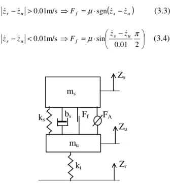
The Figure 1 presents a model for vehicles with independent suspension, where
m
srepresents a quarterof the 'sprung' mass of a vehicle,
m
uthe 'unsprung'mass of one wheel with the suspension and break equipment,
k
s the spring stiffness,k
t the tire stiffness,t
b
the damping coefficient of tire andb
s the dampercoefficient. The variable
F
frepresents the frictionforce.
The dynamic behaviour of the one-wheel suspension system may be expressed by differential equations (3.1) to (3.4). A f u s s u s s s sz k z z b z z F F
m && =− ( − )− (& − & )− +
(3.1)
A f r u t r u t u s s u s s u u F F z z b z z k z z b z z k z m − + − − − − − − + − = ) ( ) ( ) ( ) ( & & & & & &
(3.2)
The frictional force may be calculated from Rajamani
et al (2):
(
s u)
f u
s z F z z
z& −& >0.01m/s ⇒ =µ⋅sgn & −&
(3.3)
− ⋅ = ⇒ < − 2 01 . 0 sin m/s 01 . 0 f µ s u π u s z z F z
z& & & &
(3.4)
Fig 1: Vehicle suspension model.
Z
uZ
rm
sk
sb
sm
uk
tZ
sF
AF
fA simulation was then conducted with parameters from (3) and (4) and presented at Table I.
Table I - Simulation Suspension Parameters
s
m
m
uk
sk
tKg Kg N/m N/m
290 59 16,812 190,000
The equations (3.1) and (3.2) were numerically solved and the results are shown in Figure 2.
The passive sprung mass acceleration was computed using a 1000 N/m/s passive damper coefficient without coulomb friction (2). In an active suspension, to get a skyhook sprung mass acceleration the control law chosen was: ) ( s u u des A F C z B z z
F = =− ⋅& − ⋅ & −&
(3.5)
where C = 3000 N/m/s. The corresponding sprung mass accelerations are also in Figure 2 for a 2.54-cm (1-inch) sine wave road disturbances with a frequency of 1 Hz.
IV.
ELECTROMAGNETIC VEHICLE
SUSPENSIONS
Using electromagnetic linear actuators it is possible to control the force between the sprung and unsprung masses. Hence, as in a classical road vehicles suspension systems, it will be possible to obtain the required law forces to damp the sprung mass oscillations.
All the above suspension systems, passive, semi-active and active, can be built using electromagnetic actuators. The natural control flexibility of the electric equipment enables an important improvement in the suspension
behaviour. However, the other potential advantage of the electromagnetic suspensions is the possibility for then to work in the generator regime. This characteristic allows energy recovery from the suspension, when the actuator breaks the movements between the sprung and the unsprung masses, decreasing the vehicle energy consumption.
Permanent Magnets Linear Actuator
The concept of electromagnetic suspension system requires a permanent magnet linear actuator. In the recent years, the development of rare-earth magnetic materials allows the manufacture of high-energy density permanent magnets, for example the NdFeB magnets. Therefore, for the same power or torque values, it is possible to construct lighter and smaller permanent magnet motors and actuators. The radial magnetised rare earth ring magnets allow cylindrical shape actuators as it is important to adapt the electromagnetic actuator shape to the vehicle usable space.
Actually, the proposed permanent magnet linear actuator works like a permanent magnet brushless spin motor. The radial magnetised rings produce a magnetic field trough the armature windings. The rings are mounted in a driver rod made of magnetic steel. The windings are mounted inside a soft magnetic steel cylinder to improve the close loop magnetic circuits. A power electronics converter switches the winding currents according to the rings position. In the Figure 3 it is presented a possible layout of a permanent magnet brushless linear actuator.
N S N S S N N S N S N S SN N S Control System
L
+
-Converter DampingConstrain
t
Hydraulic FluidFig. 3:. Hybrid active-passive suspension
Fig. 2: Sprung mass acceleration.
V.
ELECTROMAGNETIC HYBRID
SUSPENSION
The expression (3.5) which gives the force values to be applied for obtaining the desired skyhook sprung mass acceleration presents an active and a passive component:
The first one is
s act C z
F =− ⋅& (5.1)
It is the active component of the force, and )
( s u
pas B z z
F =− & −& (5.2) represents the passive damping force.
To produce the active force it is necessary to provide an actuator in association with a control system. Otherwise, the passive force can be produced without a specific control system.
Characteristic values for these two force components are presented in Figure 4. From the graphic it is clear that the passive component presents the relative bigger values. This force depends only from the velocity between sprung and unsprung masses, so it can be out from the control system. The active component of the force presents lower peak values. These results allows to conceive a new type of suspension system. The passive forces can be obtained from an hydraulic conventional damper. They do not have any outside control. Simultaneously, the active forces are created using an electromagnetic permanent magnet linear actuator fed by a power electronics converter and an automatic control system as in Figure 3.
0,0 1000,0 2000,0 3000,0 4000,0 5000,0 6000,0 1 3 5 7 9 11 31 15 17 19 21 Frequency [Hz] P ea k F o rc e [N ] Active Passive
This layout permits the use of smaller, and lighter electromagnetic actuators keeping at same time the active suspension performance. The passive damper can be built in the electromagnetic actuator as in Figure 3 or
as separate systems and a conventional damper can work mechanically in parallel with the electromagnetic actuator.
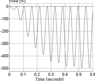
The instantaneous power from the active force is shown in figure 5 for sine wave disturbances of 9 Hz and an amplitude of 2,54 mm (0.1 inch). The negative values mean that the actuator forces are "braking" the movement and the actuator works in a "generator" regime allowing some power recovery to the automobile battery.
For the same road disturbance, the graphic of the Figure 6 shows the total instantaneous power of the actuator. In an oil-hydraulic active suspension this power is provided by the suspension hydraulic pump and can not be recovered.
VI.
CONCLUSIONS
In this paper an hybrid suspension system which combines a passive damper with an electromagnetic actuator is proposed. The objective is to achieve a performance similar to that the obtained from an active Fig. 4:. Suspension actuator peak forces
Fig. 5:. Actuator active instantaneous power
suspension system but using a smaller and lighter electromagnetic actuator
The performance analysis of an active suspension system has shown that is possible to split the forces developed by the actuator in components related with a passive and an active mode. A passive conventional damper can develop the passive component of the desired force. The active component of the force to be provided by the electromagnetic actuator is then significantly reduced.
The proposed system consumes energy from the suspension power source only to provide the active force whereas for the hydraulic active suspensions the source must provide both forces. It means that there is a significantly reduced energy consumption in the proposed system when compared to a conventional active one.
Electromagnetic levitation systems applied to railway vehicles are an important research and development subject. Here the vehicle, due the magnetic or electromagnetic forces, levitates over the “road” surface – which it is a pair of rails or a monorail. A control system regulates the force between the track and the vehicle body, allowing the stability of the vertical position. In these systems, the sprung mass vertical accelerations are not dependent of the track irregularities. Such vehicles can ride at higher speeds not only because there are no rolling and slipping friction but, also, because they are isolated from oscillations due the track irregularities.
The levitation forces are generated by powerful windings acting in the made-of-magnetic-material track. To avoid thermal losses, the windings are made of superconductor wires and are cooled by a cryogenic system. This conducts to the conclusion that there is no direct application of these systems to road automobiles. However, was shown that some of the electromagnetic levitation fundaments can be applied to the road vehicles.
There is no possibility of the generation of an electromagnetic field between the vehicle body and the non-magnetic-material in the road surface, but using electromagnetic linear actuators it is possible to control the force between the sprung and unsprung masses. Hence, as in classical road vehicles suspension systems, it is be possible to derive the required law forces to damp the sprung mass oscillations. With an adequate control system it will be then possible to regulate the vehicle vertical position. Then the sprung mass vertical oscillations will not only depend on road irregularities but also from the system performance.
REFERENCES
(1) Bastow, D., Car Suspension and Handling, Pentech Press Limited, London, 1987.
(2) Rajamani, R., Hedrick, K.J., "Adaptive Observers for Active Automotive Suspensions Theory and Experiment", IEEE Transactions on Control Systems Technology, Vol. 3, No 1, 1995.
(3) Alleyne, A., Hedrick K.J., "Nonlinear Adaptive Control of Active Suspensions"; IEEE Transactions on Control Systems Technology, Vol. 3, No 1, 1995. (4) Milho, J., Ambrósio, J., "Dinâmica Computacional do Veículo Lancia Stratos", Relatório IDMEC/CPM - 96/002, I.S.T., 1996.
(5) Kraus, J.D., Electromagnetics; ISBN 0-07-112666-X, McGraw-Hill, 1992.
(6) Lequesne, B., "Permanent Magnet Linear Motors for Short Strokes", IEEE Transactions on Industry Applications, Vol. 32, No 1, 1995.
(7) Rashid, M.H., Power Electronics, Circuits Devices and Applications, ISBN 0-13-686619-0, Prentice-Hall, 1988.
(8) Kassakian, J.G., Wolf, H.-C., Miller, J.M., Hurton, C.J., "Automotive Electrical Systems Circa 2005"; IEEE Spectrum, August 1996.