Development of Active Suspension System for
Automobiles using PID Controller
Mouleeswaran Senthil kumar, Member, IAENG
Abstract-The main aim of suspension system is to isolate a vehicle body from road irregularities in order to maximize passenger ride comfort and retain continuous road wheel contact in order to provide road holding. The present work aims at developing an active suspension for the quarter car model of a passenger car to improve its performance by using a proportional integral derivative (PID) controller. The controller design deals with the selection of proportional, derivative gain and integral gain parameters (Kp, Ki, and Kd). The results show that the active suspension system has reduced the peak overshoot of sprung mass displacement, sprung mass acceleration, suspension travel and tire deflection compared to passive suspension system.
Index Terms-Active suspension, Quarter car
model, PID controller, Random road, Step road.
NOTATION
Ai : amplitude of ith sine wave, m c1 : damping coefficient, N s/m F ; actuator force, kN
Kp : proportional gain Kd : derivative gain Ki : integral gain
k1 : spring stiffness, kN/m k2 : tire stiffness, kN/m m1 : quarter car sprung mass, kG m2 : unsprung mass, kG
: waviness of road
n1 : fundamental natural frequency, Hz n2 : second natural frequency, Hz S : static deflection of the tire spring, m, s : Laplace operator
i : uniformly distributed phase angles in the range between 0 and 2π
Ωi : wave number T : time, sec W : road profile, m
x1 : sprung mass vertical displacement, m x2 : unsprung mass vertical displacement, m
Manuscript received on October 10, 2007. (Mouleeswaran senthil kumar is with Department of Mechanical Engineering, PSG College of Technology, Coimbatore 641 004, India. (Phone: 91-422-2513730; fax: 91-422-2573833; e-mail: msenthil_kumar@hotmail.com)
x
..
1 : sprung mass accelearation,m/s 2 x1-x2: suspension travel, m
x2-w: tire deflection, m
z(s) : distance along the road, m
1. INTRODUCTION
Suspension systems have been widely applied to vehicles, from the horse-drawn carriage with flexible leaf springs fixed in the four corners, to the modern automobile with complex control algorithms. The main aim of suspension system is to isolate a vehicle body from road irregularities in order to maximize passenger ride comfort and retain continuous road wheel contact in order to provide road holding [1]. Demands for better ride comfort and controllability of road vehicles like passenger cars has motivated to develop new type of suspension systems like active and semi active suspension systems. These electronically controlled suspension systems can potentially improve the ride comfort as well as the road handling of the vehicle [2]. An active suspension system has the capability to adjust itself continuously to changing road conditions. By changing its character to respond to varying road conditions, active suspension offers superior handling, road feel, responsiveness and safety [3].
In this paper an attempt is made to develop an active suspension with PID controller to improve the performance of suspension system and performance is verified with MATLAB 7.0.1.
2. MATHEMATICAL MODELING
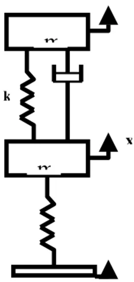
In this work, a quarter car model with two degrees-of-freedom is considered instead of full model. It not only leads to simplify the analysis but also represents most of the features of the full model.
A. Passive Suspension System
+
P
D
u(t)
∫
t
dt
t
e
Ki
0
)
(
Kp
dt
de(t)
Kd
I
e(t)
Figure 1 Quarter car model of passive suspension
According to Newton’s second law and free body diagram approach, the equations of motion for the system are written as,
For sprung mass m1
0
)
(
)
(
2 1 1 2. 1 . 1 1 ..
1
x
+
c
x
−
x
+
k
x
−
x
=
m
(1)For unsprung mass m2
0
)
(
)
(
)
(
2 1 1 2 2 2.
1 .
1 2 ..
2
x
−
c
x
−
x
−
k
x
−
x
−
k
w
−
x
=
m
(2) B. Active Suspension System
Active suspension systems employ hydraulic or pneumatic actuators, which provide the desired force in the suspension system. Hence, clearly external force is introduced into the system by the means of hydraulic actuator [3].
For active suspension shown in Figure 2, using the Newton’s second law of motion and free-body diagram concept, the following equations of motion are derived.
0
)
(
)
(
2 1 1 2. 1 . 1 1 ..
1
x
+
c
x
−
x
+
k
x
−
x
−
F
=
m
(3)0
)
(
)
(
)
(
2 1 1 2 2 2. 1 . 1 2 ..
2
x
−
c
x
−
x
−
k
x
−
x
−
k
w
−
x
+
F
=
m
(4) A proportional-integral-derivative controller (PID controller)[7] is a common feedback loop component in industrial control systems. The difference (or "error" signal) is then used to adjust some input to the process in order to bring the process' measured value back to its desired setpoint. PID controllers do not require advanced mathematics to design and can be easily adjusted (or "tuned") to the desired application, unlike more complicated control algorithms based on optimal control theory. Figure 3 is the block diagram of the PID controller. Kp as the proportional gain, Ki as the integral gain and Kd as the derivative gain which are the parameters to be varied to tune the controller for the required performance of the system.
s
Ki
s
Kp
s
Kd
s
C
(
)
=
(
)
+
(
)
+
2
(5)
Figure 2 Quarter car model of active suspension
.
3. PID CONTROLLER DESIGN
Figure 3 PID controller
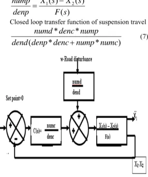
With the set point as zero, the error signal (measured variable – set point) is fed to the controller. From the block diagram shown in Figure 4, suspension travel (X1-X2) is given by,
denp
nump
X
X
denc
numc
W
dend
numd
X
X
⎥⎦
⎤
⎢⎣
⎡
−
−
=
−
)
(
)
(
1 2 1 2 (6)where
) ( )) ( ) ( (
) ( )) ( ) ( ( ) (
) (
2 1
2 1
s F s X s X
s W s X s X
s W
s F dend numd
− − =
=
s
Ki
s
Kp
s
Kd
s
C
(
)
=
(
)
+
(
)
+
2
x
m
k
m
)
(
)
(
)
(
2 1s
F
s
X
s
X
denp
nump
=
−
Closed loop transfer function of suspension travel
)
*
*
(
*
*
numc
nump
denc
denp
dend
nump
denc
numd
+
(7)Figure 4 Block diagram of closed loop system
From the block diagram shown in Figure 4, sprung mass displacement X1 is given by
denp
nump
X
X
denc
numc
W
dend
numd
X
⎥⎦
⎤
⎢⎣
⎡
−
−
=
(
1 2)
1 (8)
where
)
(
)
(
1s
F
s
X
denp
nump
=
Closed loop transfer function sprung mass displacement, 2 1 1 1 1 1 * * * * ) ( * * * ) ( * * s dend numc nump m k s c denc denp numd k s c nump denc numd − +
+ (9)
From the block diagram shown in Figure 4, sprung mass acceleration 1
..
X
is given bydenp
nump
X
X
denc
numc
W
dend
numd
X
⎥⎦
⎤
⎢⎣
⎡
−
−
=
(
1 2)
1 .. (10) where
)
(
)
(
1 ..s
F
s
X
denp
nump
=
Closed loop transfer function of sprung mass acceleration den numc nump m k s c denc denp numd k s c nump denc numd * * * ) ( * * * ) ( * * 1 1 1 1 1 − + + (11)
From the block diagram shown in Figure 4, tire deflection (X2-W) is given by
denp
nump
X
X
denc
numc
W
dend
numd
W
X
⎥⎦
⎤
⎢⎣
⎡
−
−
=
−
(
1 2)
2 (12)
where
)
(
2s
F
W
X
denp
nump
=
−
A. Tuning of PID Controller
There are several methods for tuning a PID loop [6]. Zeigler and Nichols [7] suggested rules for tuning PID controllers (meaning to set values Kp, Kd, Ki. Such rules suggest a set of values of Kp, Kd, and Ki that will give a sTable operation of the system. Kp= 3055; Kd= 32060 and Ki=0.7
4. RESULTS AND DISCUSSIONS
Calculation Natural Frequencies
The solution of the above differential equations of motion can be assumed as in the following form,
)
sin(
);
sin(
2 21
1
X
t
x
X
t
x
=
ω
=
ω
(13)By solving above two equations, we will get the two undamped natural frequencies of the system,
2 1 2 1 2 1 1 2 2 1 2 2 1 1 1
2 ( )
4 1 2
) (
2 mm
k k m k m k k m k k m k − ⎥ ⎦ ⎤ ⎢ ⎣ ⎡ + + ± + + =
ω (14)
Table 1 Parameter values used in the quarter car-model
m1 Sprung mass 250 kg
m2 Unsprung mass 50 kg
k1 Suspension spring constant 18,600 N/m c1
Suspension damping
coefficient 1,000 Ns/m k2 Tire spring constant 196,000 N/m
The above parameters are taken from reference [5]. Using the above given parameter values and
equation the natural frequencies of the system are calculated and have been obtained as:
n1=8.23 rad/s (1.31 Hz); n2=65.56 rad/s (10.4 Hz) The static deflection of the tire spring, S, can be calculated as 0.015 m
A. Time Domain Analysis
0 0.5 1 1.5 2 2.5 3 3.5 4 4.5 5 -0.02
0 0.02 0.04 0.06 0.08 0.1 0.12 0.14
Time(sec) Spr
u n g Ma s s Dis pl a c e me nt ( m )
Passive Active Road input
0 0.5 1 1.5 2 2.5 3 3.5 4 4.5 5 -0.08
-0.06 -0.04 -0.02 0 0.02 0.04
Time(sec) Tir
e d efl e cti o n (m )
Passive Active
0 0.5 1 1.5 2 2.5 3 3.5 4 4.5 5 -10
-5 0 5 10 15 20
Time(sec) Ac
c ele ra ti o n( m/s e c )
Passive Active
0 0.5 1 1.5 2 2.5 3 3.5 4 4.5 5 -0.12
-0.1 -0.08 -0.06 -0.04 -0.02 0 0.02 0.04 0.06
Time(sec) Su
s pe n sio n t ra v el( m)
Passive Active
5. STEP INPUT
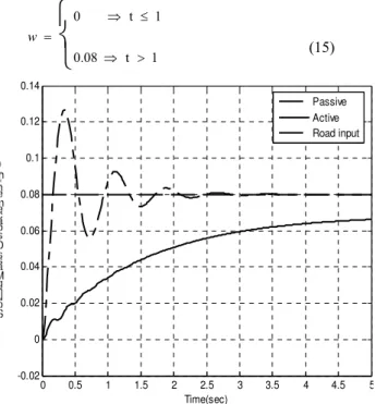
The step input characterizes a vehicle coming out of a pot hole. The pot hole has been represented in the following manner [8] for the step height of 0.08m.
⎩
⎨
⎧
> ⇒
≤ ⇒ =
1 t 0.08
1 t 0
w
(15)
Figure 5 Sprung mass displacement Vs time
From Figure 5, peak overshoot of sprung mass displacement for passive system is 0.1268 m where as for the active suspension system it is 0.0662 m.
Figure 6 Sprung mass acceleration Vs time
From Figure 6, peak overshoot of sprung mass acceleration for passive system is 17.99 m/s2 where as for the active suspension system it is 1.81 m/s2.
Figure 7 Suspension travel Vs time
Figure 8 Tire deflection Vs time
From Figure 7, maximum elongation of suspension spring for passive system is 0.04362 m where as for the active suspension system it is 0.01106 m. From Figure 8, maximum tire deflection for passive system is 0.03246 m where as for the active suspension system it is 0.0033 m.
6. RANDOM ROAD INPUT
Apart from sinusoidal bumpy and pot-hole type of roads, a real road surface taken as a random exciting function is used as input to the vehicle.
Road profiles can be approximated by PSD in the form of
0 1 2 3 4 5 6 7 8 9 10 -0.015
-0.01 -0.005 0 0.005 0.01 0.015
R o a d d is tu rb a n c e ( m )
Time (s)
0 1 2 3 4 5 6 7 8 9 10
-0.015 -0.01 -0.005 0 0.005 0.01 0.015
Time(sec) S
p u n g Ma s s D s p a c e me n m
Passive Active
0 1 2 3 4 5 6 7 8 9 10
-5 -4 -3 -2 -1 0 1 2 3 4 5
Time(sec) A
c c ele ra ti o n( m/s e c
2)
Passive Active
Φ(Ω)=Φ(Ω0)(Ω/Ω0)- (16) where Ω=2Π/L in rad/m denotes the wave number andΦ0=Φ(Ω0) in m
2
/(rad/m) describes the value of
Figure 9 Road roughness classification by ISO
PSD at reference wave number Ω0=1 rad/m. The drop in magnitude is modeled by waviness . By setting waviness to =2, each class is simply defined by its reference value Φ0
.
The ISO has proposed road roughness classification (classes A-H) based on the power spectral density values is as shown in Figure 9[9].
A random profile of single track can be approximated by superposition of NÆ∞ sine waves [9].
Road profile
where each sine wave is determined by its amplitude Ai and its wave number Ωi. By different sets of uniformly distributed phase angles i, i = 1(1)N in the range between 0 and 2π different profiles can be generated which are similar in the general appearance but different in details.
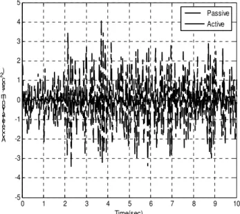
Figure 10 Sprung mass displacement Vs time
According to equation (17) the profile z = z(s) was generated by N = 10 sine waves in the frequency range from 0.1cycle/m (0.628rad/m) to 1cycle/m (6.283rad/m). The amplitudes Ai, i = 1(1)N were calculated and the MATLAB function ‘rand’ was used to produce uniformly distributed random phase angles in the range between 0 and 2π.
From Figure 10, peak overshoot of sprung mass displacement for passive system is 0.015 m where as for the active suspension system it is 0.00407 m. From Figure 11, peak overshoot of sprung mass acceleration for passive system is 4.035 m/s2 where as for the active suspension system it is 0.5156 m/s2.
From Figure 12, maximum elongation of suspension spring for passive system is 0.01536 m where as for the active suspension system it is 0.00367 m. From Figure 13, maximum tire deflection for passive system is 0.02011 m, where as for the active suspension system it is 0.007784 m. Usually for random vibration the values are measure in RMS values, which are shown in Table 2.
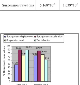
From Figure 14, that the active suspension system is better than the passive suspension system in terms of peak overshoot and settling time for the sprung mass displacement and sprung mass acceleration (Ride comfort), suspension travel(Rattle space) and tire deflection(Road holding) for both step and random road profile.
Figure 11 Sprung mass acceleration Vs time
7. CONCLUSIONS
In this paper, a PID controller has been designed for a quarter car model of a passenger car to improve the ride comfort and road holding ability. Zeigler and Nichols tuning rules are used for serious of tunings to improve the ride comfort and road holding ability. For step input the of 0.08 m, the sprung mass displacement has been reduced by 47.79% which shows the improvement in ride comfort and sprung
( )
∑
(
)
=
Ω
−
=
N
i
i
s
i
i
A
s
R
z
1
0 1 2 3 4 5 6 7 8 9 10 -0.025
-0.02 -0.015 -0.01 -0.005 0 0.005 0.01 0.015 0.02 0.025
Time(sec) S
u s pe n s o n a v e m
Passive Active
87.22
47.79
72.86 89.93
74.64 76.45 89.73
61.3
0 10 20 30 40 50 60 70 80 90 100
Step input Random input
%
R
ed
uc
ti
o
n
in peak
v
al
u
es
Sprung mass displacement Sprung mass acceleration Suspension travel Tire deflection
mass acceleration reduced by 89.93%.The suspension travel has been reduced by 74.64% and tire deflection has reduced by 89.73% . For random road input, the maximum acceleration of the sprung mass has been reduced by 87.22% which shows the improvement ride comfort. The maximum sprung mass displacement has been reduced by 72.86%.
The maximum suspension travel has been reduced by 76.45% which will improve the life of the suspension system. Active suspension reduced the tire deflection by 61.3% which shows the better road holding ability of the active suspension system.
Therefore, it is concluded that the active suspension system has better performance capabilities over passive suspension system.
Figure 12 Suspension travel Vs time
REFERENCES
1. Lin, J.S and Kanellakopoulos, I., 1997, “Nonlinear Design of ActiveSuspensions,” IEEE Control Systems Magazine, Vol. 17, No.3, pp.45-59.
2. Crosby,M. and D.C.Karnopp, 1973, “The active damper a new concept for shock and vibration control,” Shock Vibration. Bull, Part H, Washington D.C, pp. 35-42.
3. R. Rajamani and J.K. Hedrick, “Performance of Active Automotive Suspensions with Hydraulic Actuators: Theory and Experiment” Proceedings of t he American control conference June 1994.
4. Esmailzadeh, E. and Taghirad, H.D., 1994, “Active Vehicle Suspensions with Optimal State-Feedback Control,” Proceedings of CSME, Vol. 2, pp. 822-834.
5. Lin, J.S and Kanellakopoulos, I., 1997, “Modular Adaptive Design for Active Suspensions,” Proceedings of the 36th IEEE Conference on Decision and Control, San Diego, CA, pp. 3626– 3631.
6. Jacqueline wilkie, Michael Johnson and Reza Katebi, 2003,”Control Engineering: an Introductory Course”, Pal grave Publishers.
7. Ogata, K., 1996, “Modern Control Engineering,” Prentice-Hall, 3rd edition.
8. Wong, J.Y., 1988, “Theory of Ground Vehicles,” John Wiley and Sons Inc., New York.
9. Prof. Dr. George Rill “Vehicle dynamics”, University of applied sciences, October 2006.
0 1 2 3 4 5 6 7 8 9 10 -0.025
-0.02 -0.015 -0.01 -0.005 0 0.005 0.01 0.015 0.02 0.025
Time(sec) Tir
e d efl e cti o n( m )
Passive Active
Figure 13 Tire deflection Vs time
Table 2 Peak RMS values of random vibration
Parameter Passive suspension
Active suspension Sprung mass
displacement(m) 4.351*10 -3
2.669*10-3 Sprung mass
acceleration(m/s2) 1.176*10
-3 0.151*10-3
Suspension travel (m) 5.168*10-3 1.039*10-3
Figure 14 Performance of active suspension system for different road inputs
