Abstract— Particle Swarm Optimization (PSO) algorithm has been applied in electromagnetics to design microwave absorbers. Generally, microwave absorbers are used for absorbing the electromagnetic radiation caused due to numerous electronic equipments and is being extensively used in stealth technology. The main aim of this paper is to find and analyze the minimized maximum reflection coefficient over a range of frequency and angle of incidence for a fixed number of layers and polarization. An improvised PSO algorithm has been suggested by utilizing a velocity restriction factor that intelligently searches for the optimum solution. The pareto principle with an improvisation in social and cognitive parameters has also been applied. The algorithm succeeded in finding better values of reflection coefficient for the microwave absorber structures comparatively. Based on the pareto principle a form of mutation technique is also used for better convergence. The results have been compared and tabulated for various combinations of the microwave absorber structure and the thickness of each layer is also optimized for a predefined database.
Index Terms— Swarm Optimization, Reflection Coefficient, Microwave
Absorbers, Velocity Restriction, Pareto Principle
I. INTRODUCTION
Plasma stealth technology is normally used to reduce the reflection caused due to radar, infrared,
radio-frequency (RF) and visible light. This technology is widely being used in military, making it
very difficult for enemy radars to detect aircrafts and avoid being tracked by weapons guided by radar
[1]. Radar cross section gives a measure of the extent to which an aircraft is visible. For this reason,
the radar cross section factor should be reduced. Microwave absorbers are widely mounted on
surfaces to reduce the radar cross section. Absorbers are also used to reduce the radiation caused due
to huge number of equipments inside the aircraft [2]. Experiments with absorbers found earlier were
conducted by Sir J. C Bose in 1927 [3]. Two types of absorbers are normally used for this application:
resonant (frequency dependent) and broadband absorbers. Broadband absorbers are not frequency
dependent; instead they can be used over a broad spectrum [4].
Research on designs of broadband absorbers has found immense amount of interest recently [5-7].
The design of absorbers depends upon factors such as frequency, angle of incidence, permittivity,
Design of Microwave Absorbers using Improvised
Particle Swarm Optimization Algorithm
Mouna.H1, Mekaladevi. V2, Nirmala Devi. M3
Department of Electronics and Communication Engineering Amrita School of Engineering, Coimbatore
Amrita Vishwa Vidyapeetham Amrita University, India
permeability, polarization and thickness. Researchers have tried to optimize these parameters using
various evolutionary algorithms such as Genetic algorithm (GA) [8-9], Self adaptive differential
evolutionary algorithm (SADEA) [10], Simulated annealing [11], and Particle swarm optimization
(PSO) [12-13]. These algorithms have shown improvement in the design of these absorbers, however
improved even more, reducing the overhead cost. GA has its difficulties, because of its complexity
and extensive time for computation. In Simulated annealing method, it has a high tendency to get
trapped in local optimum and also takes a large convergence time [12].
Literature shows that Particle swarm optimization (PSO) outperforms GA and simulated annealing
[12]. Particle swarm optimization (PSO) is an algorithm that mimics natural behavior of a swarm
mostly found in species of birds, bees and fish. This algorithm was first introduced by Kennedy and
Eberhart in 1995 [14-15]. PSO is known for its parallelization and faster optimization. The particles in
a swarm follow a predefined pattern that is analogous to a swarm of bees searching for their food
which is the global optima. All the particles in swarm are aware of their optima and the corresponding
best global optima. The velocity and the position are the only two factors required for the particles to
move to their global optima accordingly.
PSO being faster in computational time and cost has advanced rapidly in recent years, and has
found its importance in the fields of artificial intelligence, information technology, material design
and various other fields that require faster optimization [16]. PSO can also be used for parametric
optimization with geometry. The recursive formula of Chew has been used previously to design
absorbers [17]. This formula calculates the reflection coefficient for multilayered absorber for TE and
TM polarizations. For broad angle of incidence, the reflection coefficient is calculated. TE and TM
polarizations correspond to the electric and magnetic fields respectively. Reported literature has
calculated the reflection coefficient for various numbers of layers [18], however the optimization of
these layers is a tradeoff between the thickness and the reflection coefficient. Hence algorithms that
perform better are required. Hence to give a detailed analysis on all the above mentioned factors,
improvised particle swarm optimization is used which has proved to perform better for various
benchmark functions. Comparing to other algorithms the improvised PSO outperforms the
conventional PSO algorithm and its variants.
To calculate the reflection coefficient, a five layered absorber is considered in the microwave range.
The layer optimization was performed over a broad range of incident angles and frequency for both
TE and TM polarizations. Bands such as S, C, X and Ku are considered, as the microwave
applications lie in these frequency bands. To achieve the above mentioned ascendancy over other
algorithms, three techniques have been proposed in the algorithm. In the first technique, velocity
restriction is constructed on the 80-20 rule also known as pareto principle [20]. The second technique
used is a mutation based method using the escape probability to restrict the search space and explore
extensively for the local optima. The third technique employed is an improvement to the inertial
and social parameters are two stochastic acceleration parameters that can be set accordingly to the
design requirements so the neighbor of convergence can be steered towards the personal best solution
of particle (pbest) or global best solution of swarm (gbest) based on the requirement of the algorithm.
The combination of these techniques together has achieved a better convergence and precision.
This paper contains six sections. Section 1 gives an introduction towards the explanation of the
problem statement. Section 2 illustrates the design for physical model of microwave absorbers and its
corresponding parametric requirements. The working of improvised particle swarm optimization
algorithm and specific requirements for the microwave absorbers is explained in Section 3. The
predefined database for calculation of reflection coefficient is present in Section 4. Section 5 discusses
the results for the various designs considered for achieving the best result for microwave absorber.
The analysis for the best obtained result over a range of frequency and a varied number of layers is
presented in Section 6. It is an analysis on how the frequency and angle of incidence affects the
reflection coefficient for varying number of layers. Ultimately, the best microwave absorber with the
least reflection coefficient for a particular frequency range has been suggested.
II. OVERVIEW OF MICROWAVE ABSORBERS
A Perfect Electric Conductor (PEC) layer N+1 acts as the substrate for an N planar layered
microwave absorber as illustrated in Figure 1.
Figure 1. Physical arrangement of materials for microwave absorber design [17]
An electromagnetic wave is obliquely incident on the first layer of the multilayered structure from
the free space region with an angle of incidence
𝜃
. Each layer has a thickness𝑑
𝑁. The incoming wavetravels through all the layers that form the absorber. Approximately all the power is being drawn into
by each layer which is then completely reflected by the substrate layer (PEC). The reflected power
from PEC is absorbed by the N layers above it, ultimately acting like an absorber. The reflection
coefficient between any two layers N and N+1 can be calculated using Eq. (1). Fresnel’s coefficient
complex permittivity and permeability are denoted as
𝜀
𝑖and𝜇
𝑖 for the ith layer, respectively and𝑘
𝑖denotes the wave number and is defined as given in Eq. (4)
𝑅
𝑖,𝑖+1=
1+ 𝑟𝑟𝑖,𝑖+1 𝑖,𝑖+1 + 𝑅 𝑅𝑖+1,𝑖+2𝑖+1,𝑖+2exp(−2𝑗𝑘exp(−2𝑗𝑘𝑖+1𝑖+1𝑑𝑑𝑖+1𝑖+1)) where i=1, 2, …, N & 𝒓 = 𝒓𝒕𝒆 𝒐𝒓 𝒓𝒕𝒎 (1)𝑟𝑡𝑒
𝑖,𝑖+1=
𝜇𝜇𝑖+1𝑖+1𝑘𝑘𝑖𝑖−𝜇+𝜇𝑖𝑖𝑘𝑘𝑖+1𝑖+1𝑖 < 𝑁
(2)𝑟𝑡𝑚
𝑖,𝑖+1=
𝜀𝜀𝑖+1𝑖+1𝑘𝑘𝑖𝑖−𝜀+𝜀𝑖𝑖𝑘𝑘𝑖+1𝑖+1𝑖 < 𝑁
(3)𝑘
𝑖= 𝜔√𝜇
𝑖𝜀
𝑖− 𝜇
0𝜀
0𝑠𝑖𝑛
2(𝜃)
(4)Here
𝜀
0 and𝜇
0 is the permittivity and permeability of free space and𝜔
is the angular frequency of the incident wave.𝜀
0=
8.854× 10
−12𝐹/𝑚
and𝜇
0= 4𝜋 × 10
−7𝐻/𝑚
The reflection coefficient between the penultimate and the last layer N and N+1, is considered as -1 for TE polarization and +1 for TM polarization respectively [17]. For normal incidence, the reflection coefficient bears the same result for both TE and TM polarization. Since the last interface reflection coefficient R (N, N+1) is calculated, the reflection coefficients of the subsequent layers can be calculated. Finally the required reflection coefficient R (0, 1) is obtained by recursive computation. III. IMPROVISED PARTICLE SWARM OPTIMIZATION In conventional PSO individuals evolve by competition and cooperation among themselves for a swarm of size N. The best optimum position is based on the search done by these particles in the swarm using their intelligence. PSO algorithm helps to find the optimum solutions by moving its particles in a specified search space. The movements of these particles are guided with their best known coordinates. PSO provides two such best solutions to find the optimum solution. First, personal best (pbest) which indicates the closest position achieved by the particle, in moving towards the solution. Secondly, global best (gbest) which indicates which particle in the swarm has the best position towards the solution. Based on best values the velocity and position is updated till the best solution is achieved. The equation for velocity (𝑣
𝑖𝐷) and position (x
iD) is given by Eq. (5) and Eq. (6)𝑣
𝑖𝐷= 𝑤 × 𝑣
𝑖−1𝐷+ 𝑐1 × 𝑟𝑎𝑛𝑑1
𝑖𝐷× (𝑝𝑏𝑒𝑠𝑡
𝑖𝐷− 𝑥
𝑖𝐷) + 𝑐2 × 𝑟𝑎𝑛𝑑2
𝑖𝐷× (𝑔𝑏𝑒𝑠𝑡
𝐷− 𝑥
𝑖𝐷)
(5)𝑥𝑖𝐷= 𝑥𝑖−1𝐷 + 𝑣𝑖𝐷 (6)
Where, for every objective function
f
,
w is the inertia weight, c1 and c2 are defined as thecognitive and social factors respectively. These parameters are also called learning parameters and
help to increase the search ability. Here rand1 and rand2 are the random distribution that ranges
between 0 and 1 which is generated for every D dimensions. Pbest and gbest gives the personal best
value for each particle is found for every iteration i. Techniques such as mutation, restriction and
improvised range are factors that affect velocity have been introduced, stand apart from Conventional
PSO. In the improvised PSO based on the pareto principle the search is restricted with velocity and
mutation which offers diversity in exploration. The Pareto principle states that 20 percent of the
causes are responsible for 80 percent of the outcome and vice versa [20]. Hence based on this rule the
inertia weight applied ranges from 0.8 to 0 for Eq. (7). Significantly 80% of the area is covered by the
neighborhood having a higher chance of exploration.
𝑤𝑖= 𝑤𝑚𝑎𝑥 −𝑤𝑚𝑎𝑥−𝑤𝑚𝑖𝑛𝑖𝑡𝑚𝑎𝑥 × 𝑖𝑡 (7)
Where w is the inertia weight for each iteration. wmax is taken as 0.8 and wmin as 0. Here denotes
the current iteration and itmax is the total number of iterations used which is considered as 700. The
social and cognitive factors c1 and c2 may be considered based on the requirement of the application.
Here c1 and c2 are considered as linearly decreasing and linearly increasing, respectively as given in
the Eq. (8) and Eq. (9).
𝑐1(𝑖) = (𝑐1𝑚𝑎𝑥− 𝑐1min ) × (𝑖𝑡𝑚𝑎𝑥𝑖 ) + 𝑐1𝑚𝑖𝑛 where 𝑐1𝑚𝑖𝑛= 2.5 and 𝑐1𝑚𝑎𝑥 = 0.5 (8)
𝑐2(𝑖) = (𝑐2𝑚𝑎𝑥− 𝑐2min ) × (𝑖𝑡𝑚𝑎𝑥𝑖 ) + 𝑐2𝑚𝑖𝑛
where 𝑐2𝑚𝑖𝑛= 0.5 and 𝑐2𝑚𝑎𝑥 = 2.5 (9)
For the velocity restriction mentioned above the following Eq. (10) is used to modify the effect of the
previous velocity and the current position of the particle.
𝑉𝑟 = 𝑒
−16×𝑖𝑡𝑚𝑎𝑥𝑖𝑡(10)
Here ‘Vr’ is the velocity restriction factor. The ultimate aim of the paper is to design a microwave
absorber with minimized maximum reflection coefficient and the corresponding thickness for each
layer is minimized to practical values. A predefined set of materials have been considered in various
papers. The fitness function is formulated as given in Eq. (11)
𝐹 = 𝜑
1× 20𝑙𝑜𝑔
10(max(|𝑅
0,1|)) + 𝜑
2× ∑
𝑁𝑖=1𝑑
𝑖 (11)The above fitness function has to be minimized to calculate the weighted sum of the total
maximum reflection coefficient of the absorber for a given angle of incidence and over a range of
frequencies and for TE and TM polarizations. For minimization of the fitness value, improvised
particle swarm optimization has been used and its takes into account the two factors needed to be
optimized. The fitness function is designed on focusing on obtaining the minimum reflection
coefficient and the thickness is optimized to give this minimized reflection coefficient. Here
𝜑
1and 𝜑
2 are the weighted coefficients considered to calculate the total fitness value [13]. Frequentmutations are performed to help the exploration process, determined by an escape probability. This
escape probability is calculated using an algorithm that also prevents the particle to move out of the
IV. DESIGN OF MICROWAVE ABSORBERS
The improvised PSO algorithm is applied to minimize the fitness function leading to an optimal
design for microwave absorber. For this, a predefined set of materials is considered [17].
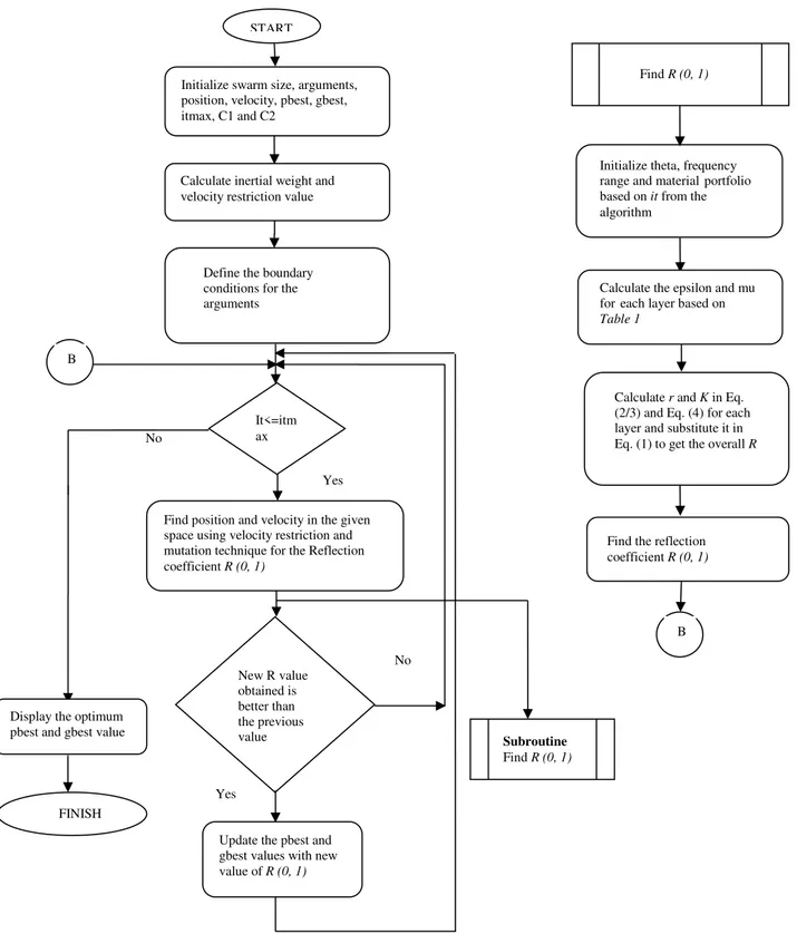
Figure 2. Flowchart for microwave absorber design using improvised PSO
Initialize swarm size, arguments, position, velocity, pbest, gbest, itmax, C1 and C2
Calculate inertial weight and velocity restriction value
It<=itm ax No
Yes
Find position and velocity in the given space using velocity restriction and mutation technique for the Reflection coefficient R (0, 1)
New Rvalue obtained is better than the previous value
No
Yes
Update the pbest and gbest values with new value of R (0, 1) Display the optimum
pbest and gbest value
FINISH
Initialize theta, frequency range and materialportfolio based on it from the algorithm
Calculate the epsilon and mu foreach layer based on Table 1
Define the boundary conditions for the arguments
Calculate r and K in Eq. (2/3) and Eq. (4) for each layer and substitute it in Eq. (1) to get the overall R
Find the reflection coefficient R (0, 1) START
Find R (0, 1)
B
Subroutine
Find R (0, 1) Yes
V. RESULTS AND ANALYSIS
The improvised Particle Swarm Optimization (PSO) is applied on the design of microwave absorbers
for various combinations of materials for 5 layers for a range of frequency and angle of incidence.
Matlab® is used for coding using a PC with core I5 4005u, 1.7Ghz and 4 GB RAM. The number of
particles in swarm is considered as 30 and 10 dimensions are considered for the five layers and their
corresponding thicknesses. The maximum layer thickness is set to 1.5mm to restrict the search
boundary. For each design presented, 700 iterations is carried out for every 20 independent trials. For
each design the frequency range considered is from 2 to 18GHz based on the application for a 0.1GHz
set. The angle of incidences considered are from
0
° to75
°for a set size of15
°.The mean and standarddeviation of the 20 trials is taken into consideration and the best is chosen for the microwave absorber
design. Here
𝜑
1𝑎𝑛𝑑 𝜑
2 is considered as 1 and 1000 respectively, for comparison. The global best(Gbest), worst, mean and standard deviation is calculated and compared with [13] as given in Table 2.
TABLE 1: DATABASE OF THE PARAMETERS CONSIDERED FOR MICROWAVE ABSORBER DESIGN.
Design No. 1 2 3 4 5 6 7 8 9 10 11
Polarization TE/TM TM TE TM TM TM TM TE TE TE TE
Angle of
incidence 0° 15° 15° 30° 45° 60° 75° 30° 45° 60° 75°
TABLE 2:GBEST COMPARATIVE RESULTS FOR 20 TRIALS
Design No.
Ref [13] Proposed Algorithm
Gbest(dB) Worst(dB) Mean(dB) Standard
deviation Gbest(dB) Worst(dB) Mean(dB)
Standard deviation 4 −15.89 −4.02 −14.45 0.81 -16.03 -13.72 -15.18 0.71 5 −22.68 −4.01 −20.05 1.09 -23.33 -19.25 -21.28 1.18 6 −25.11 −6.61 −24.85 2.32 -23.29 -20.54 -21.93 0.34 7 −22.24 −1.67 −20.23 0.85 -22.42 -18.68 -20.87 1.46 8 −10.47 −1.72 −10.05 0.27 -11.78 -9.21 -10.27 0.78 9 −8.81 −0.93 −8.23 0.36 -8.82 -6.07 -7.68 0.76 10 −5.20 0.08 −4.78 0.23 -5.25 -4.51 -4.92 0.28 11 −1.53 0.92 −1.31 0.08 -1.10 -0.20 -0.66 0.37
From Table 2 the best value, worst value, mean and standard deviation for each combination is
considered after optimization. Comparatively, except for design 6 there is an improvement for all the
other 7 designs. The Gbest value is obtained from the fitness function. It can be observed that for all
the 20 trials the best and worst values do not vary much. The reflection coefficient, materials
considered, their corresponding thickness, total thickness and arrangement of the materials has been
tabulated in Table 3 and Table 4. Design 1-3 in Table 3 is considered for the analysis of microwave
TABLE 3:PARAMETRIC REQUIREMENT FOR MICROWAVE ABSORBER DESIGNS 1-3
TABLE 4: PARAMETRIC REQUIREMENT FOR MICROWAVE ABSORBER DESIGNS 4-11 Design
No. Layer Material no. Thickness (mm) Reflection Coefficient (dB)
Total Thickness
(mm)
Design 1
1 16 0.24332
-16.102 3.2109
2 8 0.33948
3 7 0.81477
4 6 0.76302
5 15 1.05037
Design 2
1 16 0.25814
-16.594 3.27005
2 8 0.89143
3 8 0.72297
4 11 0.82739
5 10 0.57012
Design 3
1 16 0.27428
-15.309 3.19418
2 7 0.63671
3 6 1.13055
4 13 0.46773
5 15 0.68491
Design
No. Layer Material nos. Thickness (mm)
Proposed Algorithm Ref [13] RC (dB) Total Thickness (mm) RC(dB) Total Thickness* (mm) Design 4
1 16 0.22407
-20.010 3.9754 -19.306 3.4144
2 6 1.43077
3 13 0.49299
4 5 1.22021
5 10 0.60731
Design 5
1 16 0.12205
-27.316 4.2397 -26.519 3.8420
2 6 1.49978
3 14 0.38438
4 4 0.95693
5 4 1.27658
Design 6
1 7 0.97532
-27.353 4.0666 −29.149 4.0354
2 9 0.32104
3 8 0.62741
4 7 0.94466
5 4 1.19824
Design 7
1 7 0.43144
-25.558 3.1433 −25.379 3.1351
2 12 0.61446
3 2 1.49954
4 12 0.30706
5 4 0.29077
Design 8
1 16 0.22809
-15.519 3.7355 −15.393 3.6694
2 8 0.63982
3 6 1.47215
4 14 0.42288
5 9 0.97265
Design 9 1 16 0.25436
-12.521 3.714 −12.244 3.4387
2 6 1.36323
3 6 1.02108
[b] - 15° [a] - 0°
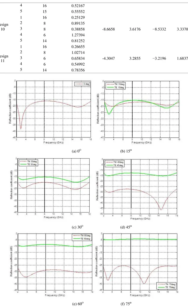
(a) 0O
(b) 15°
(c) 30O
(d) 45°
(e) 60O
(f) 75°
Figure 3.Frequence Response for Tables 3 & 4
4 16 0.52167
5 15 0.55552
Design 10
1 16 0.25129
-8.6658 3.6176 −8.5332 3.3370
2 8 0.89135
3 8 0.38858
4 6 1.27394
5 14 0.81252
Design 11
1 16 0.26655
-4.3047 3.2855 −3.2196 1.6837
2 8 1.02714
3 6 0.65834
4 6 0.54992
VI. ANALYSIS OF VARIOUS MICROWAVE ABSORBERS
The microwave absorbers are frequency independent materials and are designed according to the
range of frequency. This relation is established in Fresnel’s equation. Hence an analyis on the effect
of frequency on absorber design is conducted for various microwave absorbers from the best obtained
results. As per the literature above suggested a microwave absorber for TM polarization and for an
angle of 45 is designed using three different number of layers over three ranges of frequency S and
C band (2-8GHz), X band (8-12GHz) and Ku band (12-18GHz). Various experiments on N=2 layers
absorbers have been designed and analyzed in earlier literature [18]. The increase in the number of
layers have shown improvement in obtaining the minimum reflection coefficient. Hence this analysis
will help to choose microwave absorbers according to specific frequency band for the required
application. Also this frequency range is widely used in fields of military and civil applications. Based
on the thickness specification, the absorber can be choosen. The number of layers are considered
excluding the PEC layer and it is considered as N+1th layer which acts as the substrate for every
design. This experiment is carried out using improvised particle swarm optimization for a changing
dimension which is the number of layers and the material used. Design number 12 to 14 correspond to
absorbers with N=4 layers. Design numbers 15 to 17 correspond to absorbers with N=5 layers and
design numbers 18 to 20 correspond to absorbers with N=6 layers. Based on the number of layers N
the minimum reflection coefficient and its thickness is calculated and presented below.
TABLE 5.MICROWAVE ABSORBER DESIGN FOR N=4 FOR TM POLARIZATION
Design No. Layer Material nos. Thickness (mm) Reflection Coefficient (dB) Total Thickness (mm)
Design 12 (2-8GHz)
45°
1 16 0.27099
-26.674 3.49093
2 7 1.16000
3 3 1.10388
4 9 0.95932
Design 13 (8-12GHz)
45°
1 8 0.78582
-27.594 1.77374
2 16 0.19500
3 7 0.49050
4 15 0.30273
Design 14 (12-18GHz)
45°
1 16 0.09727
-35.056 2.10040
2 6 1.13070
3 14 0.29367
4 4 0.57876
TABLE 6.MICROWAVE ABSORBERS DESIGN FOR N=5 FOR TM POLARIZATION
Design No. Layer Material nos. Thickness (mm) Reflection Coefficient (dB) Total Thickness(mm)
Design 15 (2-8GHz) 45°
1 16 0.26315
-30.152 4.02701
2 7 0.96001
3 8 1.15852
4 10 0.60756
5 9 1.03777
Design 16 (8-12GHz) 45°
1 14 0.19051
-33.339 2.79410
2 6 0.93641
3 6 0.61459
5 10 0.36343
Design 17 (12-18GHz)
45°
1 16 0.14724
-29.535 2.15088
2 6 0.41555
3 6 0.07906
4 7 0.73426
5 11 0.77476
(a) –2GHZ –8GHZ (45O
) (b)– 8Ghz – 12GHz (45° )
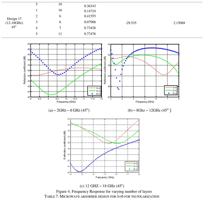
(c) 12 GHZ – 18 GHz (45o)
Figure 4. Frequency Response for varying number of layers TABLE 7.MICROWAVE ABSORBER DESIGN FOR N=6 FOR TM POLARIZATION
Design No. Layer Material nos. Thickness (mm) Reflection Coefficient (dB) Total Thickness(mm)
Design 18 (2-8GHz)
45°
1 16 0.29309
-30.848 4.41163
2 6 1.06000
3 7 0.38876
4 10 0.89880
5 10 0.80850
6 10 0.96300
Design 19 (8-12GHz)
45°
1 14 0.08386
- 35.081 3.21183
2 8 0.74699
3 7 0.90371
4 7 0.53770
5 8 0.47761
6 16 0.46124
Design 20 (12-18GHz)
45°
1 7 0.18526
-28.353 2.95384
2 16 0.15701
3 6 1.01808
4 8 0.49187
5 8 0.25507
6 11 0.84655
8 8.5 9 9.5 10 10.5 11 11.5 12
-46 -44 -42 -40 -38 -36 -34 -32 -30 -28 -26 Frequency (GHz) R e fle ct io n co e ffi ci e n t ( d B ) D=6 D=5 D=4
2 3 4 5 6 7 8
From the data available in the above Table 5, Table 6 and Table 7, a direct relation to thickness,
frequency band and number of layers can be inferred. As the thickness increases, the reflection
coefficient should also increase. For the frequency band 2-8GHz design 18 has shown the best result
for absorber design with a reflection coefficient higher than the other two designs 12 and 15
respectively, in the same band. Similarly, for the frequency band 8-12GHz design 19 has proved to be
the best comparing to design 13 and design 16. Hence in the frequency bands S, C and X microwave
absorbers with 6 layers (N=6) is advisable for minimum reflection coefficient. In the case of the
frequency band 12-18GHz design 14 proves to be the better comparing to design 17 and design 20.
Hence for X band microwave absorbers with 4 layers (N=4) is advisable for obtaining minimum
reflection coefficient.
Also based on the application if it is thickness specific, the above database will prove to be useful for
selecting the parameters required for the microwave absorber design. Based on the application and the
requirement of the range of frequency the required number of layers can be selected. Figure 4 [a], [b]
and [c] are plotted for specified range of frequency vs reflection coefficient for TM polarization for an
angle of incidence 45°.
VII. CONCLUSION
Improvised PSO has been proposed in this work for the design of microwave absorbers. For a given
range of frequency and angle of incidence, number of layers and their corresponding thickness are the
factors that can be varied in order to get a desired response. PSO variant produces the desired
response and three modifications have been tried which are, linearly varying inertia weight to design
the optimal thickness that follows the exponential rule, a mutation technique and velocity restriction
to control the convergence. This algorithm proves to be useful when quicker convergence is essential.
The algorithm has proved to design microwave absorbers with minimum reflection coefficient and it
is found to be effective for any number of dimensions. The algorithm produced the best design for
microwave absorber for TM polarization and an angle of incidence 45º in the range of frequency 2-18
GHz. Hence the obtained microwave absorber can be used for the design of stealth applications.
Comparatively, for the best design considered there is an improvement of 0.767 dB in the accuracy
and for the rest of the designs there is an improvement of more than 0.2 dB. Hence the algorithm has
proved to provide better accuracy in this field of application.
REFERENCES
[1] Swayam Arora, Ramanpreet Kaur, Stealth Technology And Counter Stealth Radars: A Review, Research Inventy: International Journal Of Engineering And Science Vol.3, Issue 12 (December 2013), PP 15-19
[2] Bowen Bai, Xiaoping Li, Jin Xu, and Yanming Liu, (2015). Reflections of Electromagnetic Waves Obliquely Incident on a Multilayer Stealth Structure With Plasma and Radar Absorbing Material .IEEE Trans. Plasma Sci., 43(8), pp.2588-2597.
[4] Jiang, L., Cui, J., Shi, L. and Li, X. (2009). Pareto optimal design of multilayer microwave absorbers for wide-angle incidence using genetic algorithms. IET Microw. Antennas Propag., 3(4), p.572.
[5] Kazemzadeh, A. and Karlsson, A. (2010). Multilayered Wideband Absorbers for Oblique Angle of Incidence. IEEE Trans. Antennas Propagat., 58(11), pp.3637-3646.
[6] Gargama, H., Chaturvedi, S. and Thakur, A. (2012). Design and optimization of multilayered electromagnetic shield using a real-coded genetic algorithm. Progress In Electromagnetics Research B, 39, pp.241-266.
[7] Ra'di, Y., Asadchy, V. and Tretyakov, S. (2013). Total Absorption of Electromagnetic Waves in Ultimately Thin Layers. IEEE Trans. Antennas Propagat., 61(9), pp.4606-4614.
[8] Chakravarty, S., Mittra, R. and Williams, N. (2001). On the application of the microgenetic algorithm to the design of broad-band microwave absorbers comprising frequency-selective surfaces embedded in multilayered dielectric media. IEEE Transactions on Microwave Theory and Techniques, 49(6), pp.1050-1059.
[9] Michielssen, E., Sajer, J., Ranjithan, S. and Mittra, R. (1993). Design of lightweight, broad-band microwave absorbers using genetic algorithms. IEEE Transactions on Microwave Theory and Techniques, 41(6), pp.1024-1031.
[10]Goudos, S. (2009). Design of microwave broadband absorbers using a self-adaptive differential evolution algorithm. Int J RF and Microwave Comp Aid Eng, 19(3), pp.364-372.
[11]R.H.J.M. Otten, and L.P.P.P. van Ginneken, The Annealing Algorithm, Kluwer, Boston, 1989.
[12]Cui, S. and Weile, D. (2005). Application of a parallel particle swarm optimization scheme to the design of electromagnetic absorbers. IEEE Trans. Antennas Propagat., 53(11), pp.3616-3624.
[13]Roy, S., Roy, S., Tewary, J., Mahanti, A. and Mahanti, G. (2015). Particle swarm optimization for optimal design of broadband multilayer microwave absorber for wide angle of incidence. Progress In Electromagnetics Research B, 62, pp.121-135.
[14]J. Kennedy and R. C. Eberhart, ‘‘Particle swarm optimization,’’ in Proc. IEEE Int. Conf. Neural Netw., Perth, Australia, 1995, vol. 4, pp. 1942--1948.
[15]R. C. Eberhart and J. Kennedy, ‘‘A new optimizer using particle swarm theory,’’ in Proc. 6th Int. Symp. Micromachine Human Sci., Nagoya, Japan, 1995, pp. 39--43. Symp. Micromachine HumanSci., Nagoya, Japan, 1995, pp. 39--43.
[16]R. C. Eberhart and Y. H. Shi, ‘‘Particle swarm optimization: Developments, applications and resources,’’ in Proc. IEEE Congr. Evol. Comput., Seoul, Korea, 2001, pp. 81--86.
[17]Dib, N., Asi, M. and Sabbah, A. (2010). On the optimal design of multilayer microwave absorbers. Pier C, 13, pp.171-185.
[18]Giannakopoulou, T., A. Oikonomou, and G. Kordas, “Double-layer microwave absorbers based on materials with large magnetic and dielectric losses,” Journal of Magnetism and Magnetic Materials, Vol. 271, 224–229, 2004.
[19]BaskaranAnand, Indoria Aakash,Akshay, VaratharajanVarrun,Murali Krishna Reddy,Tejaswi
Sathyasai,M.Nirmala Devi ,”Improvisation of Particle Swarm Optimization Algorithm,’’ inInt.Conf. Signal Processing and Integrated Networks(SPIN), India, 2014.
[20]Ankunda R. Kiremire,”The Application of Pareto Principle in Software Engineering,’’ 19th October ,2011.
![Figure 1. Physical arrangement of materials for microwave absorber design [17]](https://thumb-eu.123doks.com/thumbv2/123dok_br/16309780.718271/3.892.235.657.620.891/figure-physical-arrangement-materials-microwave-absorber-design.webp)