J. Microw. Optoelectron. Electromagn. Appl. vol.16 número3
Texto
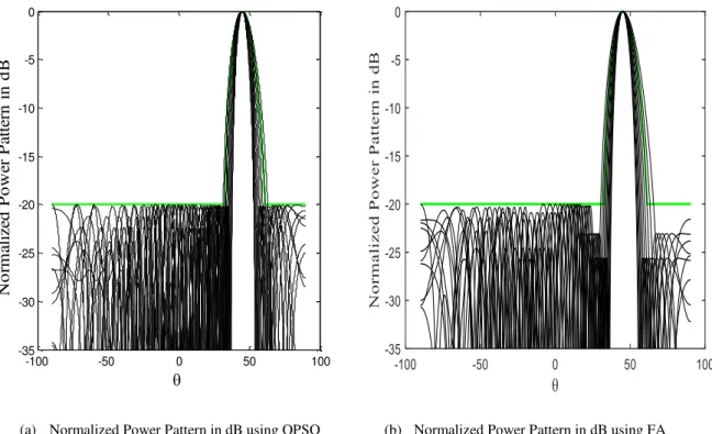
Imagem

Documentos relacionados
Zhang, “ Complex Permittivity and Permeability Measurements and Finite-Difference Time-Domain Simulation of Ferrite Materials, ” IEEE Trans. Weinschel, “ Air-filled coaxial
However, HetNets increase the complexity and cost of transport due to the large number of smallcells (SCs) that have to be connected, and hence, it is
correction-based, neural network model to predict the path loss for suburban areas at 800 MHz and 2600 MHz, obtained by combining empirical propagation models, ECC-33, Ericsson
packet using the AdFEC technique is larger than the average time to transmit a packet by using AdM. technique for Es/No ≥
Abstract — With advances in information technology for health and wellness, Smart Home-based solution providers using Internet of Things (IoT) technologies, have
Index Terms — Time-reversal ( TR) imaging, the decomposition of the time- reversal operator (DORT), Space-frequency DORT (SF-DORT), Extrapolated array,
The features of the proposed antenna such as size, bandwidth, and the number of notch bands, along with the 4 previously designed antennas are presented in Table
At last, based on the mixed-mode S parameters theory and the admittance matrix method of the two-port balanced network, a new BTSE power divider with planar
